IEEEexample:BSTcontrol
A Design Methodology for Fault-Tolerant Computing using Astrocyte Neural Networks
Abstract.
We propose a design methodology to facilitate fault tolerance of deep learning models. First, we implement a many-core fault-tolerant neuromorphic hardware design, where neuron and synapse circuitries in each neuromorphic core are enclosed with astrocyte circuitries, the star-shaped glial cells of the brain that facilitate self-repair by restoring the spike firing frequency of a failed neuron using a closed-loop retrograde feedback signal. Next, we introduce astrocytes in a deep learning model to achieve the required degree of tolerance to hardware faults. Finally, we use a system software to partition the astrocyte-enabled model into clusters and implement them on the proposed fault-tolerant neuromorphic design. We evaluate this design methodology using seven deep learning inference models and show that it is both area- and power-efficient.
1. Introduction
Modern embedded systems are embracing neuromorphic devices to implement spiking-based deep learning inference applications (Cao et al., 2015). A neuromorphic device is designed as a many-core hardware, where each core consists of silicon circuitries to implement neurons and synapses (Varshika et al., 2022). Although technology scaling has provided a steady increase of performance, increased power densities (hence temperatures) and other scaling effects create an adverse impact on the reliability by increasing the likelihood of transient, intermittent, and permanent faults in the neuron and synapse circuitries (Song and Das, 2020; Song et al., 2020). Hardware faults introduce errors in a trained deep learning model implemented on those circuitries, compromising inference quality (assessed using the accuracy metric). Therefore, providing fault tolerance is a critical requirement for neuromorphic devices.
Recent efforts to this end include software solutions such as model replication (Ponzina et al., 2021) and error prediction coding (Park et al., 2020), and hardware solutions such as approximation (Siddique et al., 2021) and redundant mapping (Yuan et al., 2021). For FPGA-based neuromorphic designs, fault tolerance can also be addressed using periodic scrubbing (Santos et al., 2014; Venkataraman et al., 2014). In this work, we propose a complimentary approach to fault tolerance. We exploit the self-repair capability of the brain, which copes with damaged neurons using astrocytes, the star-shaped glial cells of the brain (Parpura et al., 1994). Astrocytes generate an indirect retrograde feedback signal, which helps to restore the spike firing frequency of a failed neuron (Nadkarni and Jung, 2007).
We propose a design methodology for fault-tolerant neuromorphic computing, which consists of the following three components.
-
•
We propose a many-core neuromorphic design where neurons in each core are enclosed with astrocytes to facilitate self-repair of errors caused by logic and memory faults.
-
•
We introduce astrocytes in a deep learning model to achieve a desired degree of tolerance to hardware faults.
-
•
We propose a system software to partition an astrocyte-enabled inference model into clusters and implement them on the proposed fault-tolerant neuromorphic cores of the hardware.
We evaluate our design methodology using seven deep learning inference models. Results show that the proposed design methodology is both area- and power-efficient, yet providing a high degrees of fault tolerance to randomly injected faults.
2. Astrocyte Neural Networks
Figure 1 illustrates how an astrocyte regulates the neuronal activity at a synaptic site using a closed-loop feedback mechanism.
Astrocyte causes a transient increase of intracellular calcium () levels, which serves as the catalyst for self-repair. -induced release (CICR) is the main mechanism to regulate in the healthy brain. CICR is triggered by inosital 1,4,5-triphosphate (), which is produced upon astrocyte activation. To describe the operation of the astrocyte, let be a spike at time from the neuron . This spike triggers the release of 2-arachidonyl glycerol (2-AG), a type of endocannabinoid responsible for stimulating the cytosolic calcium (cyt). The quantity of 2-AG produced is governed by the ordinary differential equation (ODE)
| (1) |
where is the quantity of 2-AG, is the rate of decay and is the rate of production of 2-AG.
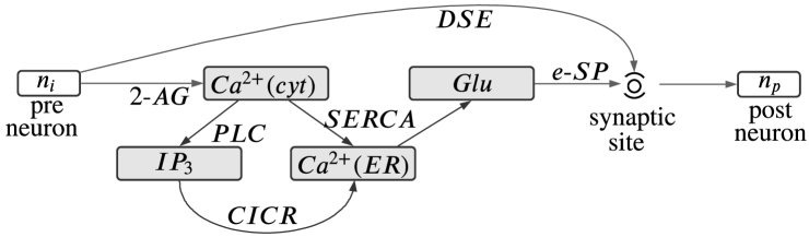
On one pathway, the cytosolic calcium is absorbed by the endoplasmic reticulum (ER) via the Sarco-Endoplasmic-Reticulum -ATPase (SERCA) pumps, and on the other pathway, the cytosolic calcium enhances the Phospholipase C (PLC) activation process. This event increases production and ER intracellular calcium release via the CICR mechanism.
The intracellular astrocytic calcium dynamics control the glutamate (Glu) release from the astrocyte, which is governed by
| (2) |
where is the rate of decay and is the rate of production of glutamate, and is time at which crosses the release threshold. The glutamate generates e-SP, the indirect signal to the synaptic site. e-SP is related to Glu using the following ODE
| (3) |
where is the decay rate of e-SP and is a scaling factor.
Finally, there exists a direct signaling pathway (DSE) from neuron to the synaptic site. The DSE is given by
| (4) |
where is a constant. Overall, the synaptic transmission probability (PR) at the synaptic site is
| (5) |
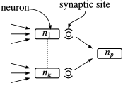
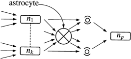
In the brain, each astrocyte encloses multiple synapses connected to a neuron. Figure 2a shows an original network of neurons, while Figure 2b shows these neurons enclosed using an astrocyte.
To understand the self-repair mechanism, consider neuron in Fig. 1 fails to fire a spike. Without the astrocyte, the spike firing rate at the synaptic site would decreases. However, because of the astrocyte, 2-AG production reduces (Eq. 1). This increases the DSE (Eq. 4). Therefore, the PR increases (Eq. 5) along with an increase of the spike firing frequency at the synaptic site.
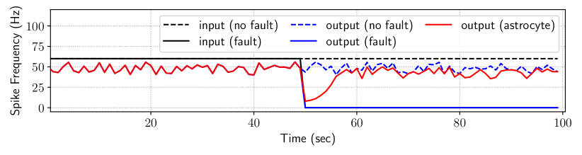
Figure 3 illustrates the self-repair mechanism. The input neuron is excited with Poisson spike events having a mean spike rate of 60Hz. We interrupt the input at around 50 sec. We observe that the firing frequency at the synaptic site connected to drops to 0. This is indicated with the label output (fault). Using astrocyte, the firing frequency can be restored partially as illustrated using the label output (astrocyte).
3. Proposed Design Methodology
3.1. Novel Hardware With Astrocyte Circuitries
Figure 4 shows the architecture of a many-core neuromorphic hardware (left sub-figure). We take the example of two recent designs – DYNAPs (Moradi et al., 2017), where each core consists of an NN crossbar with pre-synaptic neurons connected to post-synaptic neurons (middle sub-figure), and Brain (Varshika et al., 2022), where each core consists of neurons that are organized in three layers with neurons in layer 1, neurons in layer 2, and neurons in layer 3 (right sub-figure).
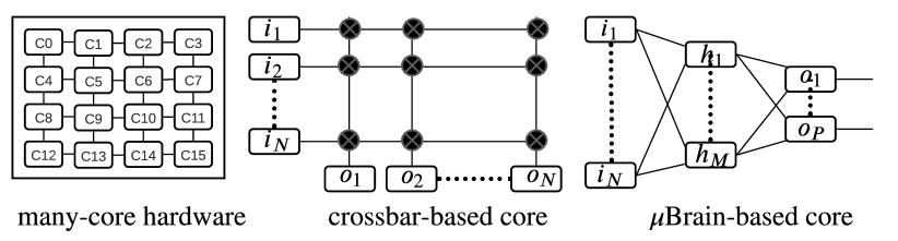
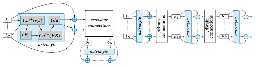
Figure 5 illustrates our proposed changes to a baseline crossbar (left sub-figure) and a baseline Brain (right sub-figure) design.
3.2. Software Mapping Framework
A single neuromorphic core can implement only a limited number of neurons and synapses. A crossbar core consists of 128 input and 128 output neurons, while a Brain core consists of 256 neurons in layer 1, 64 neurons in layer 2, and 16 neurons in layer 3. We use a distance-based heuristic (Varshika et al., 2022) to partition an inference model into clusters, where each cluster can be implemented on a core of the hardware.111Apart from distance-based heuristic, recently heuristic graph partitioning approaches are also proposed in literature (Balaji et al., 2020a; Song et al., 2021; Huynh et al., 2022). It sorts all neurons of a model based on their distances from output neurons. For Brain (crossbar) mapping, it groups all neurons with distance less than or equal to 2 (1) into clusters considering the resource constraint of a core. In the next iteration, it removes already clustered neurons from the model, recalculates neuron distances, and groups remaining neurons to generate the next set of clusters. The process is repeated until all neurons are clustered. By incorporating hardware constraints, we ensure that a cluster can fit onto the target core architecture.
3.3. Astrocyte-Enabled Inference Model
We introduce the following notations.
Algorithm 1 shows the pseudo-code to insert astrocytes in clusters of an inference model . First, it organizes the neurons of a cluster into two (for crossbar) or three (for Brain) layers (line 2). Next, for each layer it uses the ARES framework (Reagen et al., 2018) to insert random errors, one at a time and record the corresponding accuracy (line 5). If the minimum accuracy is lower than a threshold , it adds an astrocyte to the layer (lines 6-8). Otherwise, it exits and analyzes the next layer (lines 8-9). In allocating astrocytes to a layer, if more than one astrocytes are needed, then its distributes neurons of the layer equally amongst the astrocytes. and are user defined parameters and they are empirically set to 10,000 and , respectively, where is the baseline accuracy of the model without error. Finally, the astrocyte-enabled model () is returned.
4. Evaluation
Our simulation framework consists of the following.
4.1. Astrocyte Area and Power
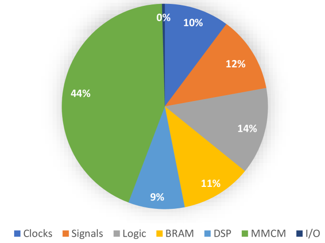
We implemented the astrocyte design, the baseline Brain and crossbar designs on Xilinx VCU128 development board (see Table 1). We observe that although an astrocyte circuitry is smaller than the size of a Brain (336 neurons) and a crossbar (256 neurons), it is in fact, significantly larger and consumes significantly higher power than a single neuron circuitry. Furthermore, an astrocyte circuitry uses more flip flops (FF), slices, and lookup tables (LUTs) than the two baseline designs. The higher area of the two baseline designs are due to the use of more block RAMs (BRAMs). The power consumption of an astrocyte design is shown in Figure 6, distributed into clocks, signals, logic, DSP, BRAM, MMCM, and I/O.
| Brain (Varshika et al., 2022) | Crossbar (Moradi et al., 2017) | Astrocyte | |
| Neurons | 336 | 256 | – |
| Synapses | 17,408 | 16,384 | – |
| Operating Frequency | 100MHz | 100MHz | 100MHz |
| BRAM | 48 | 32 | 4 |
| DSP | 0 | 0 | 4 |
| FF | 129 | 86 | 2,368 |
| Slice | 117 | 78 | 670 |
| LUT | 114 | 76 | 1,345 |
| FPGA Utilization | 49% | 40% | 12% |
| Power | 4.64W | 4.53W | 0.538 W |
4.2. Fault Tolerance
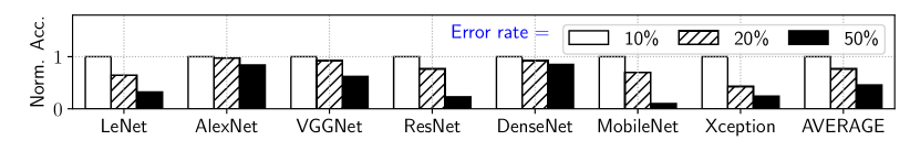
Figure 7 plots the accuracy, normalized to the replication technique, of each evaluated model for 10%, 20%, and 50% of parameters in error. These errors are injected randomly using the ARES framework (Reagen et al., 2018) and the reported results are average of 10 runs. With 10% error rate, there are only a few errors per cluster. Therefore, most errors can be masked by astrocytes that are inserted into each model cluster. So, we see no accuracy drop. With higher error rates, the accuracy is lower. This is because of the increase in parameter errors in each cluster. Errors in multiple neurons of an enclosed astrocyte impact its ability to restore the spike frequency, causing a significant amount of accuracy drop. On average, the accuracy is 23% and 54% lower for error rate of 20% and 50%, respectively.
4.3. Design Tradeoffs
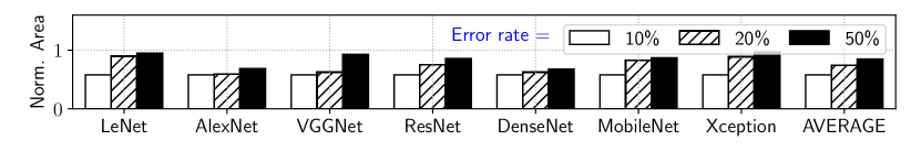
Figure 8 shows the area of a Brain-based design normalized to the replication technique for three error rates – 10%, 20%, and 30%. The accuracy constraint is set as the accuracy without error. This accuracy constraint is achieved for 10% error rate using our baseline design. So there is no area overhead. For 20% and 50% error rates, more astrocytes are needed to achieve the accuracy constraint. On average, the proposed design requires 28% and 49% higher area for 20% and 50% error rate, respectively.
4.4. Model Area
Table 2 reports the design area for each of the evaluated deep learning inference models using 1) model replication technique (Ponzina et al., 2021), 2) redundant mapping technique (Yuan et al., 2021), and 3) the proposed design methodology. Design areas are reported for both the Brain-based core (Varshika et al., 2022) and the crossbar-based core (Moradi et al., 2017). All results are normalized to the Brain-based design implementing the LeNet model using the model replication technique. We make three key observations.
| Model | Redundant | Proposed | ||||
|---|---|---|---|---|---|---|
| Replication (Ponzina et al., 2021) | Mapping (Yuan et al., 2021) | Design | ||||
| Brain | crossbar | Brain | crossbar | Brain | crossbar | |
| LeNet | 1.0 | 0.8 | – | 0.7 | 0.5 | 0.4 |
| AlexNet | 79.0 | 68.5 | – | 54.8 | 39.2 | 33.1 |
| VGGNet | 62.9 | 54.6 | – | 43.7 | 31.2 | 26.4 |
| ResNet | 1.1 | 0.9 | – | 0.8 | 0.6 | 0.5 |
| DenseNet | 13.5 | 11.7 | – | 9.4 | 6.7 | 5.7 |
| MobileNet | 4.4 | 3.8 | – | 3.0 | 2.2 | 1.8 |
| Xception | 40 | 34.7 | – | 27.7 | 19.9 | 16.8 |
First, design area is larger for models with higher number of parameters. This is because models with more parameters require more clusters (cores), which increases the design area. Second, the redundant mapping technique is only applicable to crossbar-based designs. Therefore, results for the Brain-based design are not provided. Third, for the Brain-based design, the proposed design methodology results in 50% lower area than the replication technique. For the crossbar-based design, it results in 51.6% lower area than the replication technique and 39.5% lower area than the redundant mapping technique. These improvements are because implementing a few astrocytes in a baseline Brain and crossbar designs is area-efficient than 1) replicating model clusters, which requires more cores to implement a model, and 2) redundant mapping, which requires larger crossbars to implement each cluster.
4.5. Model Power
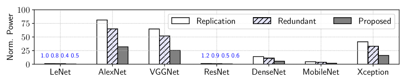
Figure 9 reports the power for each evaluated model on a crossbar-based design using the three evaluated approaches. Power numbers for each core is calculated based on the static power of the design and the activation of the synaptic weights in the core (Titirsha et al., 2021). We make two key observations. First, power is higher for models such as AlexNet, VGGNet, and Xception due to higher number of model parameters. Second, on average, power using the proposed design methodology is 60% lower than replication technique and 50% lower than redundant mapping technique. For Brain-based design (not shown here for space limitations), power using the proposed methodology is 60% lower than the replication technique.
5. Conclusions
We propose a design methodology for fault-tolerant neuromorphic computing. First, we propose a novel design, where a core consists of neuron, synapse, and astrocyte circuitries. Each astrocyte encloses multiple neurons to facilitate self-repair of a failed neuron. Next, we insert astrocytes in an inference model to achieve the desired degree of fault tolerance. Finally, we propose a system software framework to map astrocyte-enabled inference model to the proposed fault-tolerant many-core design. We evaluate the proposed design methodology using several deep learning models on the fault-tolerant implementation of two baseline neuromorphic designs. We show that the proposed design methodology is both area and power-efficient, yet providing similar degrees of fault tolerance compared to existing approaches.
Acknowledgements.
This work is supported by the National Science Foundation Faculty Early Career Development Award CCF-1942697 (CAREER: Facilitating Dependable Neuromorphic Computing: Vision, Architecture, and Impact on Programmability).References
- Balaji et al. (2020b) A. Balaji et al., “PyCARL: A PyNN interface for hardware-software co-simulation of spiking neural network,” in IJCNN, 2020.
- Balaji et al. (2020a) A. Balaji et al., “Mapping spiking neural networks to neuromorphic hardware,” TVLSI, 2020.
- Cao et al. (2015) Y. Cao et al., “Spiking deep convolutional neural networks for energy-efficient object recognition,” IJCV, 2015.
- Huynh et al. (2022) P. K. Huynh et al., “Implementing spiking neural networks on neuromorphic architectures: A review,” arXiv, 2022.
- Moradi et al. (2017) S. Moradi et al., “A scalable multicore architecture with heterogeneous memory structures for dynamic neuromorphic asynchronous processors (DYNAPs),” TBCAS, 2017.
- Nadkarni and Jung (2007) S. Nadkarni et al., “Modeling synaptic transmission of the tripartite synapse,” Physical Biology, 2007.
- Park et al. (2020) S. Park et al., “Low-cost prediction-based fault protection strategy,” in CGO, 2020.
- Parpura et al. (1994) V. Parpura et al., “Glutamate-mediated astrocyte–neuron signalling,” Nature, 1994.
- Ponzina et al. (2021) F. Ponzina et al., “E2CNNs: Ensembles of convolutional neural networks to improve robustness against memory errors in edge-computing devices,” TC, 2021.
- Reagen et al. (2018) B. Reagen et al., “Ares: A framework for quantifying the resilience of deep neural networks,” in DAC, 2018.
- Santos et al. (2014) R. Santos et al., “Criticality-aware scrubbing mechanism for SRAM-based FPGAs,” in FPL, 2014.
- Siddique et al. (2021) A. Siddique et al., “Exploring fault-energy trade-offs in approximate DNN hardware accelerators,” in ISQED, 2021.
- Song and Das (2020) S. Song et al., “A case for lifetime reliability-aware neuromorphic computing,” in MWSCAS, 2020.
- Song et al. (2020) S. Song et al., “Improving dependability of neuromorphic computing with non-volatile memory,” in EDCC, 2020.
- Song et al. (2021) S. Song et al., “DFSynthesizer: Dataflow-based synthesis of spiking neural networks to neuromorphic hardware,” TECS, 2021.
- Stimberg et al. (2019) M. Stimberg et al., “Modeling neuron–glia interactions with the Brian 2 simulator,” in Computational Glioscience, 2019.
- Titirsha et al. (2021) T. Titirsha et al., “On the role of system software in energy management of neuromorphic computing,” in CF, 2021.
- Varshika et al. (2022) M. L. Varshika et al., “Design of many-core big little Brains for energy-efficient embedded neuromorphic computing,” in DATE, 2022.
- Venkataraman et al. (2014) S. Venkataraman et al., “A bit-interleaved embedded hamming scheme to correct single-bit and multi-bit upsets for SRAM-based FPGAs,” in FPL, 2014.
- Yuan et al. (2021) G. Yuan et al., “Improving DNN fault tolerance using weight pruning and differential crossbar mapping for ReRAM-based edge AI,” in ISQED, 2021.