Propagation-invariant space-time supermodes in a multimode waveguide
Abstract
When an optical pulse is spatially localized in a highly multimoded waveguide, its energy is typically distributed among a multiplicity of modes, thus giving rise to a speckled transverse spatial profile that undergoes erratic changes with propagation. It has been suggested theoretically that pulsed multimode fields in which each wavelength is locked to an individual mode at a prescribed axial wave number will propagate invariantly along the waveguide at a tunable group velocity. In this conception, an initially localized field remains localized along the waveguide. Here, we provide proof-of-principle experimental confirmation for the existence of this new class of pulsed guided fields, which we denote ‘space-time supermodes’, and verify their propagation invariance in a planar waveguide. By superposing up to 21 modes, each assigned to a prescribed wavelength, we construct space-time supermodes in a 170-micron-thick planar glass waveguide with group indices extending from to . The initial transverse width of the field is 6 microns, and the waveguide length is 9.1 mm, which is the associated Rayleigh range. A variety of axially invariant transverse spatial profiles are produced by judicious selection of the modes contributing to the ST supermode, including single-peak and multi-peak fields, dark fields (containing a spatial dip), and even flat uniform intensity profiles.
I Introduction
Recent interest in multimode fibers has been driven by an anticipated data crunch in which the ever-increasing demand for high-bandwidth communication services may be thwarted by the limited capacity of single-mode fibers [1, 2]. Consequently, significant efforts have hitherto been directed to developing developing strategies for increasing data transmission rates via multimode fibers [3, 4, 5, 6, 7, 8]. However, a multimode field in a fiber or waveguide does not maintain its transverse spatial profile. Indeed, when pulsed light is focused into a highly multimode waveguide, the field energy is typically distributed among a multiplicity of modes, resulting in the emergence of a random speckle pattern whose transverse spatial intensity profile undergoes erratic changes with propagation along the waveguide.
A different approach to achieving propagation invariance in a pulsed multimode waveguide field was suggested in [9, 10, 11] that makes use of so-called X-waves. In free space, X-waves are superluminal propagation-invariant pulsed beams [12, 13, 14, 15, 16]. By exciting a spatio-temporal field structure at the waveguide entrance that corresponds to a spectrally discretized X-wave, a pulsed supermode propagates invariantly along the waveguide [9, 10, 11]. However, synthesizing X-waves requires ultrabroadband sources [17, 18], the observed deviation in their group velocity from that of a conventional wave packet is extremely small in the paraxial regime [19, 20, 21], and coupling them to a waveguide poses substantial experimental difficulties. As such, X-wave supermodes in multimode waveguides have to date remained theoretical entities. Additionally, the propagation of so-called focused-wave modes (FWMs [22]) in single-mode fibers has been examined theoretically [23, 24]. However, the synthesis of FWMs in the optical domain suffers the same challenges as do X-waves [25].
The intrinsic challenges involved in synthesizing X-waves have been recently resolved by the devleopment of so-called ‘space-time’ (ST) wave packets [26, 27, 28, 25]: propagation-invariant [29, 30, 31, 32, 33, 34], narrowband, paraxial pulsed beams whose group velocity can be tuned in free space [35, 31, 32, 36] or transparent dielectrics [37]. A host of novel phenomena have been recently demonstrated using ST wave packets including anomalous refraction [38, 39], ST Talbot effects [40] and dispersion-free propagation in dispersive media [41, 42, 43, 44, 45, 46, 47, 48], to name a few [25]. The versatility of this new class of propagation-invariant pulsed beams suggests their suitability as a platform for synthesizing propagation-invariant supermodes in multimode waveguides. Indeed, discretizing the spectrum of a ST wave packet may yield propagation-invariant pulsed fields in a highly multimoded waveguides. We denote such field configurations ‘ST supermodes’. Recent theoretical studies have been directed along these lines, including investigations of linear and nonlinear generation of ST supermodes in planar multimode waveguides [49] and in multimode fibers [50], and the prediction of so-called helicon wave packets that incorporate orbital angular momentum into the ST supermode [51].
Here we formulate theoretically and verify experimentally the existence of this new class of propagation-invariant pulsed fields compatible with multimode waveguides that we call ST supermodes. An ideal ST supermode is a superposition of monochromatic waveguide modes that propagates invariantly at a prescribed group velocity, which can be tuned continuously across the subluminal and superluminal regimes. These surprising features of ST supermodes rely on careful selection of the wavelength and axial wave number of each mode in the superposition. In realistic ST supermodes, each mode is associated not with a single wavelength, but rather with a narrow spectral uncertainty that is nevertheless much smaller than the full supermode bandwidth. In our proof-of-principle experiments, we synthesize and launch ST supermodes comprising up to 21 modes in a planar waveguide in the form of a 170-m-thick glass slide with free-space cladding and substrate at a wavelength of 800 nm. Using a spatio-temporal pulsed-beam shaper, we prepare in free space superpositions of waveguide modes assigned to prescribed optical frequencies, resulting in ST supermodes with tunable group velocity and characteristic X-shaped spatio-temporal profiles. Rather than the erratic speckle patterns resulting from a conventional superposition of the waveguide modes, the time-averaged intensity of the ST supermode is axially invariant; in other words, an initially localized ST supermode remains localized along the waveguide. The field is initially localized toa 6-m-wide transverse intensity feature, so that the waveguide length corresponds to the associated Rayleigh range. Moreover, by judicious selection of the modes contributing to the ST supermode, the time-averaged transverse intensity profile can be modified. We thus produce a variety of profiles, including ones with a single or multiple peaks, dark profiles (a central dip), and even flat uniform profiles.
II Theory of guided space-time supermodes
II.1 Free ST wave packets
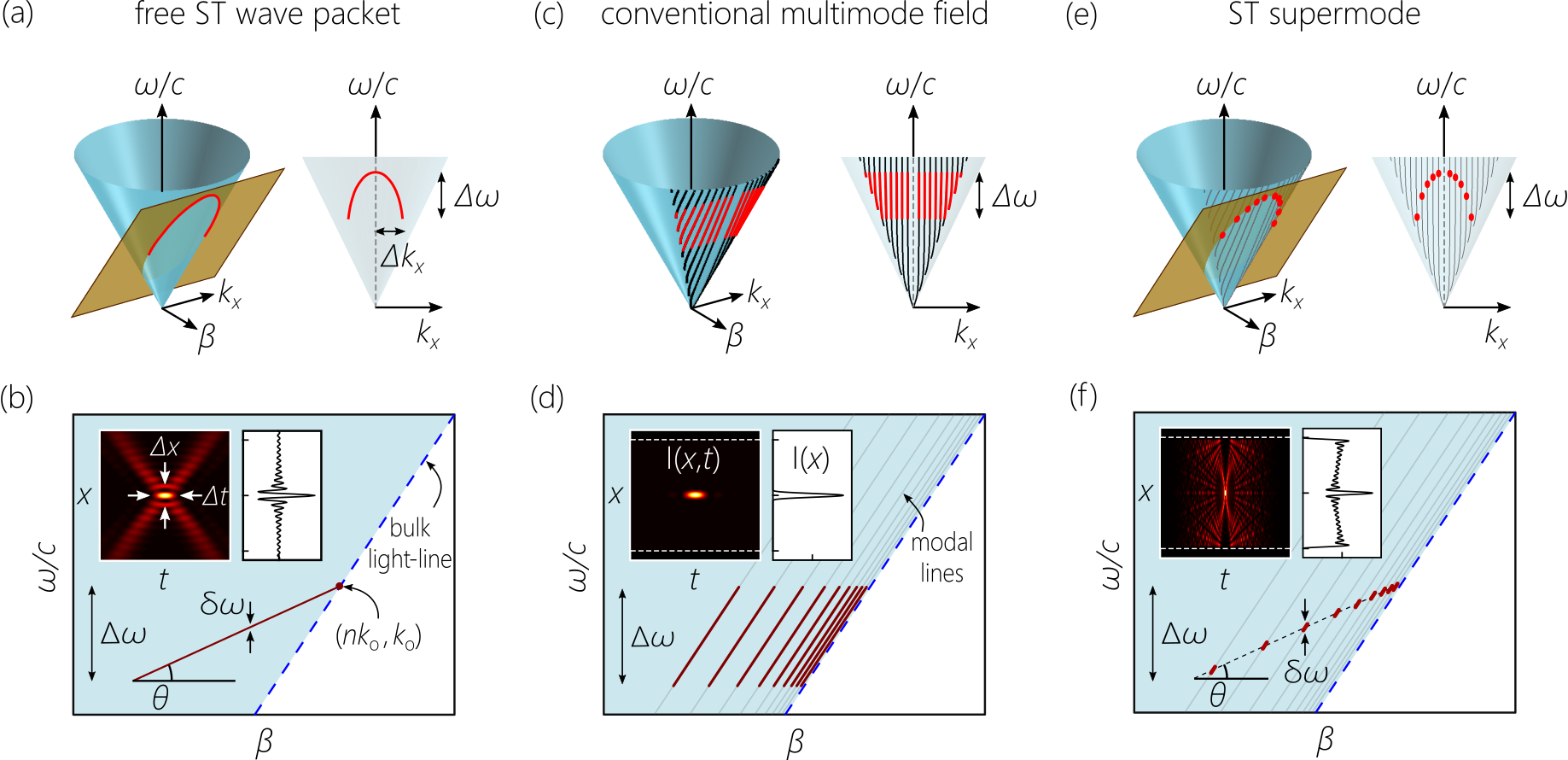
We start by briefly describing freely propagating ST wave packets, which can be visualized in terms of their spectral support domain on the surface of the light-cone. In a medium of refractive index , the light-cone corresponds to the dispersion relationship [Fig. 1(a)], where is the speed of light in vacuum, is the temporal frequency, and and are the transverse and longitudinal components of the wave vector along the transverse and axial coordinates and , respectively [52, 53, 25]; we restrict ourselves in this proof-of-principle experiment to a single transverse coordinate for simplicity. This formulation is suitable for ST supermodes in a planar waveguide, and we discuss below the prospects for producing ST supermodes in conventional waveguides where the field is confined in both transverse coordinates.
The spectral support domain for a ST wave packet on the light-cone surface is a one-dimensional (1D) trajectory – namely, the conic section at the intersection of the light-cone with a spectral plane , where is a fixed temporal frequency, the associated wave number, , and is its group velocity [29, 36]; see Fig. 1(a,b). This spectral plane is parallel to the -axis, and makes an angle (the spectral tilt angle) with the -axis, where , and is the group index. Each frequency is thus associated with a single spatial frequency . The ST wave packet travels rigidly in the medium at a group velocity that can in principle take on arbitrary values: subluminal ( is the maximum frequency in the spectrum) or superluminal ( is the minimum frequency) [37, 38]. The ST wave packet has spatial and temporal bandwidths and , respectively [Fig. 1(a)], and typically has a spatio-temporal profile at every axial plane that is X-shaped with a transverse width at the pulse center , and a pulse of width at the beam center [Fig. 1(b), inset]. Other spatio-temporal profiles can be synthesized by modulating the spectral phase (e.g., Airy ST wave packets [54] and ST caustics [55]). The time-averaged intensity takes the form of a localized spatial feature at atop a constant background [Fig. 1(b), inset].
The ideal scenario in which each frequency is associated with a single spatial frequency results in infinite-energy wave packets [56]. In realistic scenarios, each is associated with a finite spectral uncertainty [Fig. 1(b)]. In this case, the ST wave packet has finite energy, and also a finite propagation distance [57]. We have shown that the realistic ST wave packet can be decomposed into a product of the ideal ST wave packet traveling at and a ‘pilot envelope’ of temporal width traveling at . Axial walk-off between these two field structures occurs when the ST wave packet reaches the edge of the pilot envelope (when ), whereupon the spatio-temporal X-shaped profile of the ST wave packet is deformed, and the field diffracts [26, 57].
II.2 Conventional multimode-waveguide field
Consider the field in a multimode planar waveguide of refractive index and thickness , with free space on both sides. The spectral representation for each guided mode is a 1D curve on the surface of the light-cone [Fig. 1(c)]. When a pulse of bandwidth and finite spatial width is launched into the waveguide, its energy is typically distributed among a multiplicity of modes. If the input field at is , where is the carrier frequency, is the initial transverse spatial profile, and is the initial temporal profile, then the multimode-waveguide field can be written as:
| (1) |
here, is the spatial profile of the -mode (integer is the modal index), which we take to be approximately wavelength-independent (in light of the small bandwidth employed in our experiments), its axial wave number estimated at , , and is an axial envelope:
| (2) |
where and are the group velocity and GVD coefficient for the -mode evaluated at , respectively. The time-averaged intensity is:
| (3) |
where the function is defined as:
| (4) |
By defining the complex field quantities as and , we have , where .
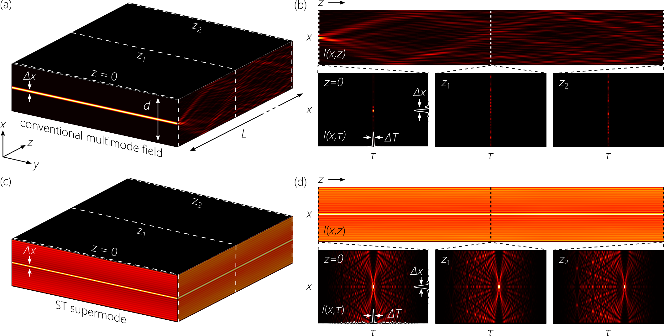
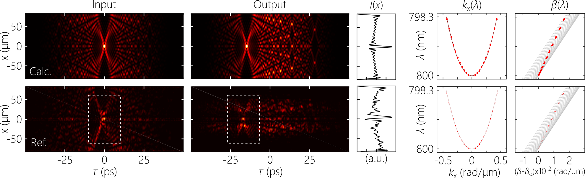
Consequently, the spectral support domain for this conventional pulsed multimode field in a planar waveguide is a collection of 1D trajectories, all potentially of bandwidth [Fig. 1(c,d)]. The field is a superposition of waveguide modes, but the field collectively is not propagation invariant. Indeed, an initially localized field at the waveguide entrance spreads spatially along the transverse dimension [Fig. 2(a)], and typically displays a speckle structure whose intensity distribution undergoes irregular changes with propagation [Fig. 2(b)].
II.3 Ideal ST supermodes
ST supermodes present an altogether different picture from that of conventional pulsed multimode fields. An ST supermode is a pulsed field in a multimode waveguide whose spectral support domain is the intersection of those for two distinct field configurations: (1) the spectral support associated with a conventional multimode waveguide field, which is the collection of 1D trajectories on the light-cone surface corresponding to the waveguide modes [Fig. 1(c,d)]; and (2) the spectral support for an ST wave packet, which is the conic section at the intersection of the light-cone with a spectral plane [Fig. 1(a,b)]. The resulting spectral support domain for an ST supermode is therefore a set of points [Fig. 1(e,f)], each representing a monochromatic mode: the -mode is associated with a frequency and an axial wave number . The total temporal bandwidth is , but the spectrum is discretized at frequencies [Fig. 1(f)]. The ST supermode field can be written as , where the envelope is:
| (5) | |||||
that is, the envelope travels rigidly at a group velocity . The spatio-temporal profile of the ST supermode [Fig. 1(f), inset] has a central X-shaped feature similar to its free-space counterpart [Fig. 1(b), inset], which travels at the group velocity . This group velocity is essentially independent of the group velocities of the underlying modes. Because of spectral discretization [40], the axial profile of the ST supermode extends beyond the central X-shaped feature associated with a freely propagating continuous-spectrum ST wave packet [Fig. 1(a,b)]. We discuss below the temporal extent of the ST supermode once we introduce the associated spectral uncertainty.
Unlike a conventional pulsed multimode field [Fig. 1(c,d) and Fig. 2(a,b)] that evolves erratically along the propagation axis, the time-averaged intensity of the ST supermode is given by:
| (6) |
which is altogether independent of [Fig. 2(c,d)]. This is a general statement that is independent of the details of the waveguide and of the superposition weights. In general, the time-averaged intensity takes the form of a central localized spatial feature atop a constant background (which, however, can be purposefully modified as shown in Fig. 7 below).
II.4 Realistic ST supermodes in presence of spectral uncertainty
In practice, a realistic ST supermode will be a superposition of modes centered at the frequencies , but have finite spectral uncertainties rather than being ideally monochromatic [Fig. 1(e,f)], so that the field envelope becomes:
| (7) |
The field combines features from the conventional pulsed multimode field (Eq. 1) and that of the ideal ST supermode (Eq. 5). The axial envelope in Eq. 7 has the same form as in Eq. 2, but with one crucial difference: the integration is carried out for each mode over a small bandwidth centered at (rather than over the full bandwidth ), so that the impact of GVD is significantly reduced. Assuming a Gaussian spectral profile for each mode to replace , we have:
| (8) |
here , is the sign of the GVD coefficient, and is the dispersion length. Each axial envelope can be viewed as a ‘pilot envelope’ traveling at a group velocity and having a dispersion length . The central X-shaped spatio-temporal feature of the ST supermode travels at the tunable group velocity , which is essentially independent of , but the axial extent of the spatio-temporal profile is determined by . Axial walk-off thus occurs between the X-shaped feature and the overall pilot envelope, reaching the edge of the envelope when .
However, the propagation of a ST supermode offers a surprising contrast to that of a freely propagating ST wave packet. The time-averaged intensity of the realistic ST supermode once again takes the form , which is independent of , just as in the case of the ideal ST supermode (Eq. 6), as long as the spectral support domains of the underlying modes do not overlap spectrally. In other words, even after the central X-shaped feature has disappeared beyond the edge of the pilot envelopes , the time-averaged intensity remains stable. In contrast, a freely propagating ST wave packet diffracts after this axial distance [57, 37].
III Experiment
III.1 Waveguide sample
We make use of a planar waveguide in the form of a borosilicate glass slide (Schott D263) of refractive index at nm, which is held in free space so that the substrate and cladding have . The dimensions of the waveguide are as follows: thickness m along ; length mm along ; and width mm along . Optical-quality facets are produced by cleaving. The waveguide is highly multimoded with TM modes at nm. The transverse spatial profiles of the low-order modes are practically identical to the corresponding modes in a waveguide formed of two perfect mirrors sandwiching a layer of the same thickness and refractive index , which are sinusoids having a single transverse wave number . Significant deviation between these two classes of modes occurs only for higher-order modes ( overlap for ).
III.2 ST wave-packet synthesis in free space
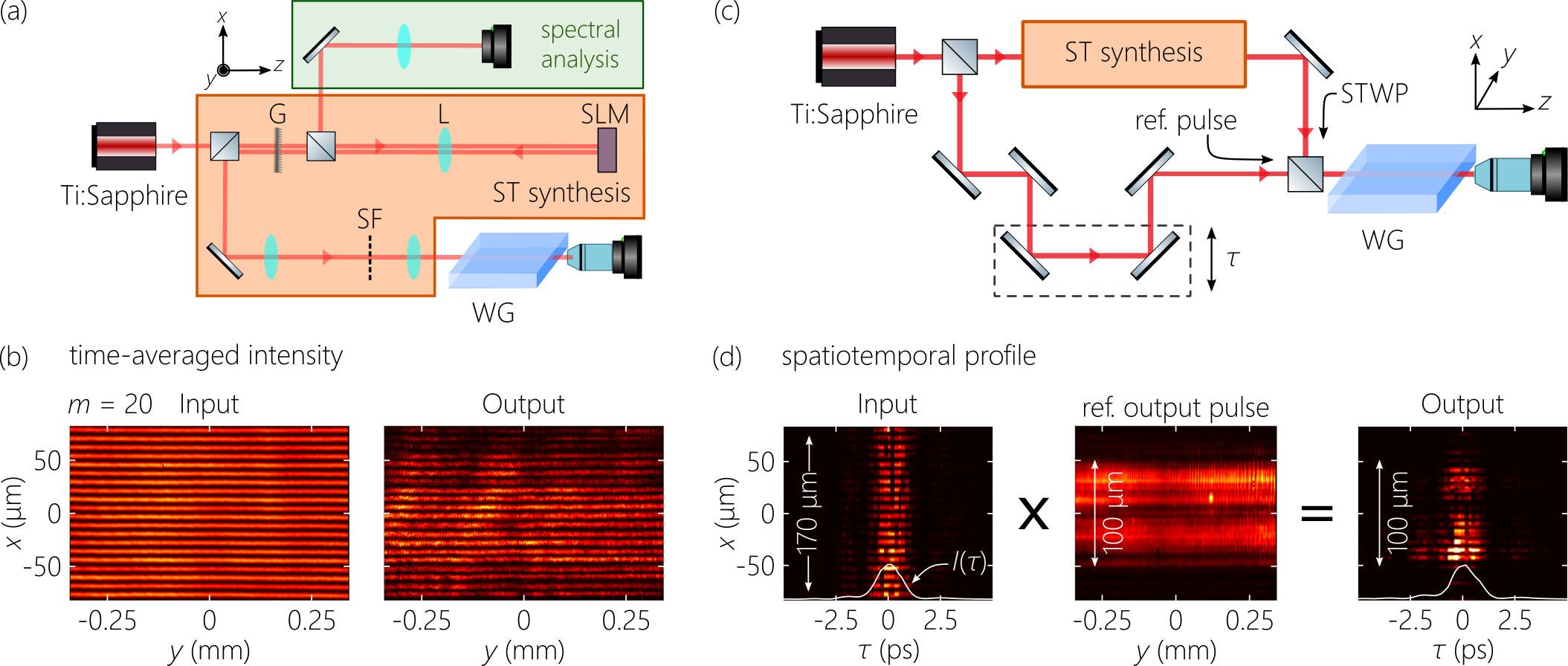
The experimental arrangement for synthesizing ST supermodes and coupling them to the waveguide is depicted in Fig. 3(a). We first spatially expand pulses from a Ti:sapphire laser (Coherent, MIRA; pulsewidth fs, bandwidth nm) to extend over 25 mm. The pulse spectrum is resolved spatially via a diffraction grating (1200 lines/mm), the wavefront corresponding to the second diffraction order is collimated via a cylindrical lens (focal length mm), and is directed to a reflective, phase-only spatial light modulator (SLM; Hamamatsu X10468-02). The SLM intercepts a portion of the spectrally resolved wavefront corresponding to a bandwidth nm (pulsewidth ps).
A portion of the wavefront retro-reflected from the SLM undergoes a spatial Fourier Transform implemented via a lens, and then directed to a CCD camera [Fig. 3(a)]. This reveals the spatio-temporal spectrum projected onto the -plane and verifies that the targeted spectral structure is synthesized. This spectrum takes the approximate form of a parabola [36, 38], where is the group index of the ST field in free space and is the free-space spectral tilt angle. We can estimate from the curvature of the measured spatio-temporal spectrum. The group index of the ST supermode in the waveguide of refractive index is related to the free-space value via the following relationship [38]:
| (9) |
We have ignored here chromatic dispersion in the waveguide material, which can be easily accounted by by a modification of Eq. 9; see [58, 59].
The wavefront retro-reflected from the SLM returns to the grating where the ST wave packet is formed. A imaging system incorporating a spatial-frequency stop-filter in the Fourier plane eliminates the unscattered field component. The synthesized optical field delivered to the waveguide entrance has a width m along , thus not requiring a coupling lens. The polarization of the field corresponds to a TM waveguide mode.
III.3 Launching individual waveguide modes
We confirm in Fig. 3(b) the ability to excite individual waveguide modes using our field-synthesis arrangement. Each wavelength in the spectrally resolved wavefront occupies a column in the SLM active area, along which we impart a phase distribution corresponding to a prescribed spatial frequency . To excite a single waveguide mode, we hold fixed for all ; i.e., the SLM phase pattern is independent of . We plot in Fig. 3(b) the measured transverse intensity profiles for the TM mode at the waveguide entrance and exit, verifying the expected propagation invariance of individual modes. The time-averaged intensity of the ST wave packet at the entrance or exit of the waveguide is captured by a CCD camera (The ImagingSource, DMK 27BUP031) equipped with an objective lens (Olympus PLN ).
III.4 Time-resolved measurements
We reconstruct the spatio-temporal profile of the ST supermodes by modifying the interferometric technique used in our previous work for freely propagating ST wave packets [57, 38]. We co-launch the ST wave packet ( nm and ps) into the waveguide along with a plane-wave reference pulse from the initial laser ( nm and fs); see Fig. 3(c). The ST supermode travels along the waveguide at a tunable group velocity , whereas the reference pulse travels at , where is the group index of the reference pulse in the waveguide. Because and the reference pulse is coupled predominantly to the fundamental mode, . When the two pulsed fields overlap in space and time at the CCD at the waveguide exit, spatially resolved interference fringes are observed. By scanning an optical delay in the path of the reference pulse [Fig. 3(c)], the intensity profile of the ST wave packet can be reconstructed from the visibility of the interference fringes. By repeating the measurements at the waveguide input, we can estimate the relative group delay between the ST supermode and the reference pulse incurred upon traversing the waveguide. Finally, using this arrangement, we can also estimate the group velocity of the ST supermode in free space . This measurement can then be compared to the value of the free-space spectral tilt angle estimated from the measured spatio-temporal spectrum [Fig. 3(a)].
The measured spatio-temporal profile of the waveguide mode is reconstructed in Fig. 3(d), which reveals that the modal profile is separable with respect to the spatial and temporal degrees of freedom. The measurements in Fig. 3(d) highlight a drawback of our approach for reconstructing the spatio-temporal profiles of the ST supermodes. Because the reference pulse is coupled into the fundamental waveguide mode (to avoid transverse spatial field variations), its intensity drops in the vicinity of the waveguide walls. We hence cannot reconstruct the profile of the ST supermode in those areas, and we are confined to a width of m of the full 170-m-wide waveguide.
IV Excitation and characterization of Space-time supermodes
IV.1 Conventional multimode field
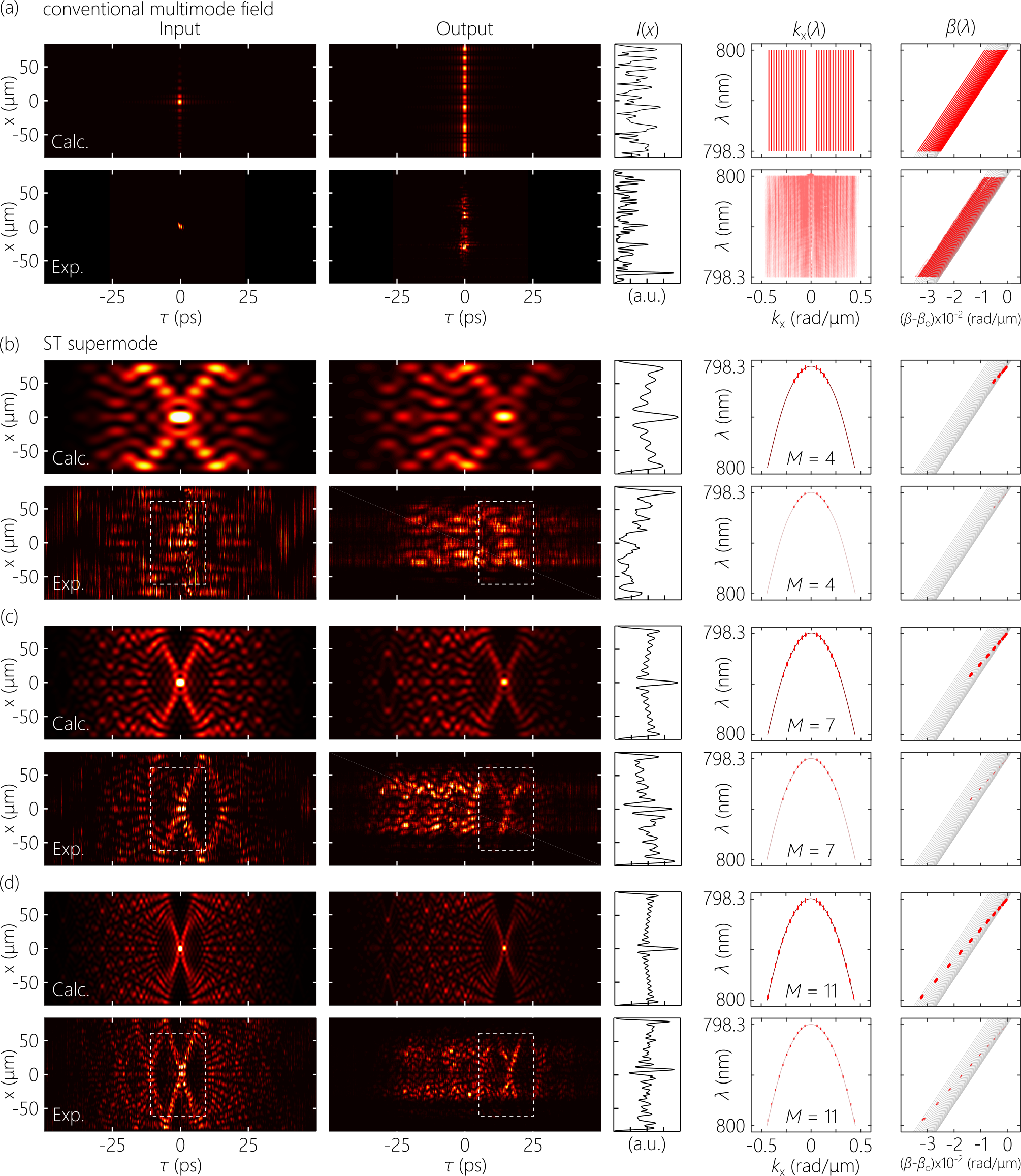
As a basis for comparison, we examine the propagation of a conventional pulsed multimode field along the waveguide. On the SLM we place a quadratic phase pattern that produces a -m-wide focused field along . The imaging system after the diffraction grating further reduces the beam width by , resulting in a beamwidth m at the waveguide entrance. The calculated and measured spatio-temporal profiles at the waveguide input and output are plotted in Fig. 4(a). The initial spatio-temporal profile is separable in space and time, with temporal linewidth ps. The initially localized profile along spreads across the waveguide width before reaching the exit. The time-averaged intensity takes the form of a speckle pattern. Although a multiplicity of modes are excited, the waveguide length and modal dispersion are not sufficiently large to produce temporal spreading. The pulse width at the waveguide output is thus approximately equal to that at the entrance. The acquired spatio-temporal spectrum is separable with respect to and , with spatial and temporal bandwidths rad/m, and nm, respectively.
IV.2 Spectral discretization and formation of ST supermodes
To excite an ST supermode, we superpose waveguide modes, each associated with a single wavelength, by modifying the 2D phase distribution imparted by the SLM to the impinging spectrally resolved wavefront. Because each wavelength is incident along a different SLM column, we impart the transverse wave number associated with the approximate waveguide mode to the selected wavelength. The bandwidth intercepted by the SLM is nm spread across 800 pixels ( pm/pixel). However, the spectral resolution of the grating is pm, corresponding to pixels. We associate SLM pixels (spectral uncertainty pm, corresponding to a pulsewidth ps) with each mode. Therefore, in the process of synthesizing ST supermodes, the field spectrum is discretized. We assign zero-phase at the SLM to the unwanted wavelengths, which are thereby eliminated via the Fourier spatial filter.
We plot in Fig. 4(b-d) the calculated and measured spatio-temporal intensity profiles for ST supermodes at the waveguide entrance and exit , which incorporate an increasing number of waveguide modes: [Fig. 4(b)], [Fig. 4(c)], and [Fig. 4(d)]. We select here even-parity modes (cosine-like profiles) indexed by , with integer (the modes corresponding to are eliminated by the spatial filter). Several conclusions can be readily drawn from the measurements. First, the spatial and temporal bandwidths increase with , so that the spatial width at the pulse center decreases from m () to m (), and the temporal linewidth at the beam center concomitantly decreases from ps () to ps (). Consequently, the characteristic X-shaped central feature in the spatio-temporal profile becomes better-defined with increasing . Second, the spatio-temporal profile at the exit resembles that at the entrance except for two aspects of the X-shaped central feature: (a) it is delayed with respect to the conventional pulsed multimode field (which travels at a group velocity ), thus confirming the subluminal group velocity of the ST supermode; and (b) its position is shifted with respect to the pilot envelope that travels at the same group velocity of the conventional pulsed multimode field. The spectral uncertainty for each mode is pm, and the pilot envelope has a temporal width of pm. The impact of GVD on these pilot envelopes is thus negligible. Third, the time-averaged intensity measured directly at the waveguide exit by the CCD camera in all cases takes the form of a spatial feature atop an approximately constant pedestal. Fourth, the spatio-temporal spectrum is non-separable with respect to and , and takes the form of discrete features (each corresponding to an individual mode) along the parabolic spectrum associated with its freely propagating ST wave packet counterpart having the same group velocity. Finally, the dispersion relationship between and takes the form of discrete points along a line whose slope corresponds to the group velocity of the ST supermode.
IV.3 Tuning the group velocity of ST supermodes
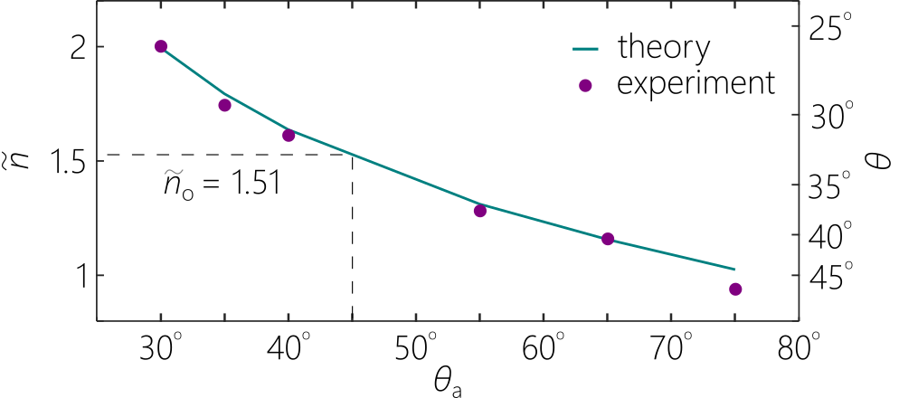
As shown in Fig. 4(b-d), the X-shaped central feature reaches the waveguide exit at , indicating that the ST supermode is slower than the conventional pulsed multimode field [Fig. 4(a)]; here is measured in the frame of the conventional pulsed multimode wave packet. If a superluminal ST supermode is synthesized instead, the central peak arrives earlier at than the conventional pulsed field. An example is shown in Fig. 5 for (). All the other features of the ST supermode remain intact, except for the reversal of the sign of curvature of the spatio-temporal spectrum . Moreover, the group velocity of the ST supermodes can be tuned continuously by altering the spectral tilt angle of the free-space ST wave packet before coupling to the waveguide. In Fig. 6 we plot the estimated ST-supermode group index (or spectral tilt angle , ) extracted from the measured group delay with respect to the reference pulse while varying . In free space, () separates the subluminal and superluminal regimes, whereas () separates them in the waveguide. We confirm the tunability of for the ST supermode in the waveguide across both the subluminal and superluminal regimes, producing group indices for the ST supermode extending from to .
IV.4 Changing the spatial profile of ST supermodes
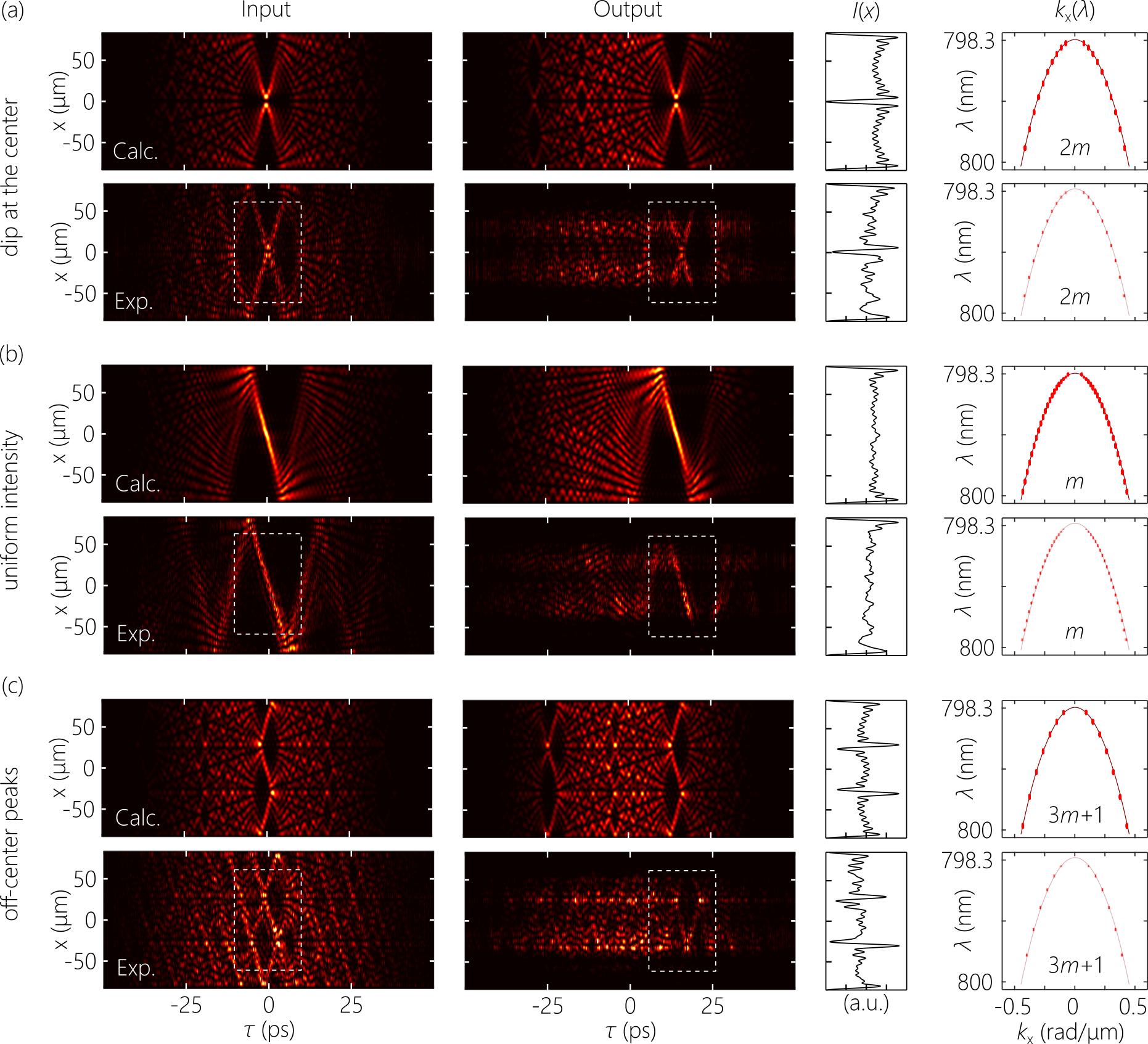
The X-shaped spatio-temporal profile of the ST supermodes in Fig. 4(b-d) and the attendant time-averaged intensity peak at the center of the waveguide are a result of choosing only even-parity modes to contribute to the ST supermode. Incidentally, previously demonstrated ST wave packets, whether X-waves or FWMs in free space, have all been X-shaped. However, it has recently been recognized that modulating the spatio-temporal phase can produce propagation-invariant wave packets in free space that are not X-shaped [54, 55]. In the context of a ST supermode, modifying the spatio-temporal structure can be realized by careful selection of the waveguide modes that enter into its construction, as demonstrated in Fig. 7. By selecting odd-parity modes indexed by , with to 10, a dip is introduced into the center of the X-shaped spatio-temporal profile and in the time-averaged intensity [Fig. 7(a)].
Interestingly, when selecting consecutive modes from to (comprising alternating even- and odd-parity modes), the X-shaped feature is eliminated and we are left with one branch of that profile [Fig. 7(b)]. The time-averaged intensity profile is uniform across the waveguide width and remains so with axial propagation. Finally, by selecting modes indexed by (comprising non-consecutive even- and odd-parity modes) from to (a total of 6 modes), two off-center peaks are created as shown in Fig. 7(c). A variety of other structures of ST supermodes may be produced by judicious choice of the modes and their relative weights.
V Discussion
Although the investigation of free-space ST wave packets extends back to the theoretical breakthrough by Brittingham in 1983 [22], only recently has rapid experimental progress been realized [25]. The key to these advances is that ST wave packets can be synthesized with smaller bandwidths and numerical apertures than X-waves or FWMs, while simultaneously offering more versatility with respect to the group-velocity tunability [53, 25]. These features, which make ST wave packets a useful platform for synthesizing ST supermodes, stem from a unique attribute of ST fields: they incorporate non-differentiable angular dispersion into their structure [60, 61]. In other words, each frequency propagates at a slightly different angle such that its derivative is not defined at some frequency . It is this non-differentiability that allows for the group velocity of ST wave packets to be tuned across the subluminal and superluminal regimes in the vicinity of without recourse to large bandwidths or leaving the paraxial regime [61].
These unique features of ST wave packets have consequently led to increasing interest in guided ST fields [50, 49, 51, 24, 62]. In addition to the ST supermodes reported here, so-called ‘hybrid ST modes’ have been recently synthesized in single-mode [63] and multimode [64] planar waveguides. It is important to delineate here these two classes of guided ST fields: ST supermodes and hybrid ST modes in a planar waveguide. In both cases we make use of ST wave packets in the form of a light sheet that is localized along one transverse dimension (say ) and extended along the other (say ). In the case of a hybrid ST mode, the -axis is aligned with the normal to the waveguide walls. Consequently, the field is localized along one dimension by the confinement mechanism provided by the waveguide, and along the other by the new spatio-temporal structure introduced into the field. The ST wave packet structure in this case can be used to override the usual characteristics of the conventionally guided mode (e.g., eliminate chromatic and modal dispersion, and tune the group index). In contrast, the -axis in the case of ST supermodes is parallel to the planar waveguide walls, and the modulated spatio-temporal structure ‘interacts’ with the interfaces, so that the ST field is constrained to be a superposition of waveguide modes, thereby necessitating spectral discretization. Both of these novel classes of confined fields (hybrid ST modes and ST supermodes) exhibit characteristics that are distinct from those of conventional guided fields.
We have couched our work here in terms of planar-waveguide modes. Can ST supermodes be extended to conventional waveguides in which light is confined in both transverse dimensions? The recent development of so-called 3D ST wave packets that are localized in all dimensions makes this a realizable prospect [65, 66, 67], especially using the methodology outlined in [66] that exploits a spectrally discrete laser comb, whereupon each line in the comb is associated with a particular spatial mode. We therefore expect ST supermodes to be realized in conventional waveguides and fibers in the near future.
Finally, we relate ST supermodes to other recent developments in the physics of optical waveguides. A recent advance has been the realization of ‘principal modes’ in a multimode fiber [68, 69]. Waveguide modes are propagation eigenmodes only in absence of scattering. In presence of scattering, new eigenmodes of a selected length of the scattering/dispersive waveguide system can be formed by superposing modes at the same wavelength. Although such a principle mode is not invariant along the fiber, it does reproduce the input field distribution at a prescribed output plane. In contrast, ST supermodes remain invariant along the fiber by exploiting the spectral degree of freedom along with the spatial; thus, ST supermodes must be pulsed. However, ST supermodes are not immune to scattering. It would therefore be useful to construct ‘principal ST supermodes’ that combine the features of both: propagation invariance and immunity to scattering.
Moreover, ST supermodes are related to the recently studied behavior of optical fields interacting with components moving at relativistic speeds [70]. Indeed, ST wave packets can be viewed as the result of implementing Lorentz transformation on a monochromatic beam [71, 72, 73]. For example, a monochromatic laser beam viewed by a detector moving at a velocity becomes a propagation-invariant ST wave packet of group velocity [54]. In this context, a monochromatic field coupled into a waveguide moving at a relativistic velocity induces a multi-chromatic discrete spectral field in the waveguide [74]. Our experiments here are thus a confirmation of this result, but with the waveguide stationary while the source is moving with respect to it. This shows the potential utility of ST wave packets in studying interactions between optical fields and moving components in general.
VI Conclusion
In conclusion, we have synthesized and observed propagation-invariant ST supermodes in a highly multimoded planar waveguide: a superposition of waveguide modes each assigned to a prescribed wavelength and axial wave number. Precise control over the wavelength and axial wave number assigned to each mode produces an X-shaped spatio-temporal profile that travels rigidly along the multimode waveguide at a prescribed group velocity independently of the group velocity of the waveguide modes. A localized ST supermode at the waveguide input remains localized at its exit, and its time-averaged intensity profile is axially invariant. The propagation-invariance of the spatio-temporal profile is limited by the spectral uncertainty: the finite but small spectral bandwidth assigned to each mode in the ST supermode. By combining up to 21 waveguide modes, we have verified the tunability of the ST-supermode group velocity, and observed a variety of structured intensity profiles, including a dark ST supermode (a dip traveling at the waveguide center), and a flat supermode (a constant intensity profile across the wavelength). These results pave the way to the delivery of pulsed excitations with custom spatial profiles through multimode fibers for linear or nonlinear sensing, imaging, and spectroscopy, and to novel multimode nonlinear interactions in optical waveguides.
Funding
U.S. Office of Naval Research (ONR) contracts N00014-17-1-2458 and N00014-20-1-2789.
Disclosures. The authors declare no conflicts of interest.
References
- Mitra and Stark [2001] P. P. Mitra and J. B. Stark, Nonlinear limits to the information capacity of optical fibre communications, Nature 411, 1027 (2001).
- Richardson [2010] D. J. Richardson, Filling the light pipe, Science 330, 327 (2010), https://www.science.org/doi/pdf/10.1126/science.1191708 .
- Ryf et al. [2013] R. Ryf, S. Randel, N. K. Fontaine, M. Montoliu, E. Burrows, S. Corteselli, S. Chandrasekhar, A. H. Gnauck, C. Xie, R.-J. Essiambre, P. J. Winzer, R. Delbue, P. Pupalaikis, A. Sureka, Y. Sun, L. Grüner-Nielsen, R. V. Jensen, and R. Lingle, 32-bit/s/Hz spectral efficiency WDM transmission over 177-km few-mode fiber, in Optical Fiber Communication Conference/National Fiber Optic Engineers Conference 2013 (Optica Publishing Group, 2013) p. PDP5A.1.
- van Uden et al. [2014] R. G. H. van Uden, R. A. Correa, E. A. Lopez, F. M. Huijskens, C. Xia, G. Li, A. Schülzgen, H. de Waardt, A. M. J. Koonen, and C. M. Okonkwo, Ultra-high-density spatial division multiplexing with a few-mode multicore fibre, Nature Photonics 8, 865 (2014).
- Sillard et al. [2016] P. Sillard, D. Molin, M. Bigot-Astruc, K. D. Jongh, F. Achten, A. M. Velázquez-Benítez, R. Amezcua-Correa, and C. M. Okonkwo, Low-differential-mode-group-delay 9-LP-mode fiber, J. Lightwave Technol. 34, 425 (2016).
- Xiong et al. [2018] W. Xiong, C. W. Hsu, Y. Bromberg, J. E. Antonio-Lopez, R. Amezcua Correa, and H. Cao, Complete polarization control in multimode fibers with polarization and mode coupling, Light: Science & Applications 7, 54 (2018).
- Pauwels et al. [2019] J. Pauwels, G. Van der Sande, and G. Verschaffelt, Space division multiplexing in standard multi-mode optical fibers based on speckle pattern classification, Scientific Reports 9, 17597 (2019).
- Zhou et al. [2021] Y. Zhou, B. Braverman, A. Fyffe, R. Zhang, J. Zhao, A. E. Willner, Z. Shi, and R. W. Boyd, High-fidelity spatial mode transmission through a 1-km-long multimode fiber via vectorial time reversal, Nature Communications 12, 1866 (2021).
- Zamboni-Rached et al. [2001] M. Zamboni-Rached, E. Recami, and F. Fontana, Superluminal localized solutions to Maxwell equations propagating along a normal-sized waveguide, Phys. Rev E 64, 066603 (2001).
- Zamboni-Rached et al. [2002] M. Zamboni-Rached, K. Z. Nóbrega, E. Recami, and H. E. Hernández-Figueroa, Superluminal X-shaped beams propagating without distortion along a coaxial guide, Phys. Rev. E 66, 046617 (2002).
- Zamboni-Rached et al. [2003] M. Zamboni-Rached, F. Fontana, and E. Recami, Superluminal localized solutions to Maxwell equations propagating along a waveguide: the finite-energy case, Phys. Rev. E 67, 036620 (2003).
- Lu and Greenleaf [1992] J.-Y. Lu and J. F. Greenleaf, Nondiffracting X waves – exact solutions to free-space scalar wave equation and their finite aperture realizations, IEEE Trans. Ultrason. Ferroelec. Freq. Control 39, 19 (1992).
- Saari and Reivelt [1997] P. Saari and K. Reivelt, Evidence of X-shaped propagation-invariant localized light waves, Phys. Rev. Lett. 79, 4135 (1997).
- Reivelt and Saari [2003] K. Reivelt and P. Saari, Localized wave solutions of the scalar homogeneous wave equation and their optical implementation, arxiv:physics/0309079 (2003).
- Turunen and Friberg [2010] J. Turunen and A. T. Friberg, Propagation-invariant optical fields, Prog. Opt. 54, 1 (2010).
- Hernández-Figueroa et al. [2014] H. E. Hernández-Figueroa, E. Recami, and M. Zamboni-Rached, eds., Non-diffracting Waves (Wiley-VCH, 2014).
- Saari [1996] P. Saari, Spatially and temporally nondiffracting ultrashort pulses, in Ultrafast Processes in Spectroscopy, edited by O. Svelto, S. De Silvestri, and G. Denardo (Springer US, Boston, MA, 1996) pp. 151–156.
- Grunwald et al. [2003] R. Grunwald, V. Kebbel, U. Griebner, U. Neumann, A. Kummrow, M. Rini, E. T. J. Nibbering, M. Piché, G. Rousseau, and M. Fortin, Generation and characterization of spatially and temporally localized few-cycle optical wave packets, Phys. Rev. A 67, 063820 (2003).
- Bonaretti et al. [2009] F. Bonaretti, D. Faccio, M. Clerici, J. Biegert, and P. Di Trapani, Spatiotemporal amplitude and phase retrieval of Bessel-X pulses using a Hartmann-Shack sensor, Opt. Express 17, 9804 (2009).
- Bowlan et al. [2009] P. Bowlan, H. Valtna-Lukner, M. Lõhmus, P. Piksarv, P. Saari, and R. Trebino, Measuring the spatiotemporal field of ultrashort Bessel-X pulses, Opt. Lett. 34, 2276 (2009).
- Kuntz et al. [2009] K. B. Kuntz, B. Braverman, S. H. Youn, M. Lobino, E. M. Pessina, and A. I. Lvovsky, Spatial and temporal characterization of a bessel beam produced using a conical mirror, Phys. Rev. A 79, 043802 (2009).
- Brittingham [1983] J. N. Brittingham, Focus wave modes in homogeneous Maxwell’s equations: Transverse electric mode, J. Appl. Phys. 54, 1179 (1983).
- Vengsarkar et al. [1992] A. M. Vengsarkar, I. M. Besieris, A. M. Shaarawi, and R. W. Ziolkowski, Closed-form, localized wave solutions in optical fiber waveguides, J. Opt. Soc. Am. A 9, 937 (1992).
- Ruano et al. [2021] P. N. Ruano, C. W. Robson, and M. Ornigotti, Localized waves carrying orbital angular momentum in optical fibers, J. Opt. 23, 075603 (2021).
- Yessenov et al. [2022a] M. Yessenov, L. A. Hall, K. L. Schepler, and A. F. Abouraddy, Space-time wave packets, arXiv:2201.08297 (2022a).
- Kondakci and Abouraddy [2016] H. E. Kondakci and A. F. Abouraddy, Diffraction-free pulsed optical beams via space-time correlations, Opt. Express 24, 28659 (2016).
- Parker and Alonso [2016] K. J. Parker and M. A. Alonso, The longitudinal iso-phase condition and needle pulses, Opt. Express 24, 28669 (2016).
- Yessenov et al. [2019a] M. Yessenov, B. Bhaduri, H. E. Kondakci, and A. F. Abouraddy, Weaving the rainbow: Space-time optical wave packets, Opt. Photon. News 30, 34 (2019a).
- Kondakci and Abouraddy [2017] H. E. Kondakci and A. F. Abouraddy, Diffraction-free space-time beams, Nat. Photon. 11, 733 (2017).
- Porras [2017] M. A. Porras, Gaussian beams diffracting in time, Opt. Lett. 42, 4679 (2017).
- Efremidis [2017] N. K. Efremidis, Spatiotemporal diffraction-free pulsed beams in free-space of the Airy and Bessel type, Opt. Lett. 42, 5038 (2017).
- Wong and Kaminer [2017] L. J. Wong and I. Kaminer, Ultrashort tilted-pulsefront pulses and nonparaxial tilted-phase-front beams, ACS Photon. 4, 2257 (2017).
- Kondakci et al. [2018] H. E. Kondakci, M. Yessenov, M. Meem, D. Reyes, D. Thul, S. R. Fairchild, M. Richardson, R. Menon, and A. F. Abouraddy, Synthesizing broadband propagation-invariant space-time wave packets using transmissive phase plates, Opt. Express 26, 13628 (2018).
- Wong et al. [2020] L. J. Wong, D. N. Christodoulides, and I. Kaminer, The complex charge paradigm: A new approach for designing electromagnetic wavepackets, Adv. Sci. 7, 1903377 (2020).
- Salo and Salomaa [2001] J. Salo and M. M. Salomaa, Diffraction-free pulses at arbitrary speeds, J. Opt. A 3, 366 (2001).
- Kondakci and Abouraddy [2019] H. E. Kondakci and A. F. Abouraddy, Optical space-time wave packets of arbitrary group velocity in free space, Nat. Commun. 10, 929 (2019).
- Bhaduri et al. [2019] B. Bhaduri, M. Yessenov, and A. F. Abouraddy, Space-time wave packets that travel in optical materials at the speed of light in vacuum, Optica 6, 139 (2019).
- Bhaduri et al. [2020] B. Bhaduri, M. Yessenov, and A. F. Abouraddy, Anomalous refraction of optical spacetime wave packets, Nat. Photon. 14, 416 (2020).
- Allende Motz et al. [2021] A. M. Allende Motz, M. Yessenov, and A. F. Abouraddy, Isochronous space-time wave packets, Opt. Lett. 46, 2260 (2021).
- Hall et al. [2021a] L. A. Hall, M. Yessenov, S. A. Ponomarenko, and A. F. Abouraddy, The space-time Talbot effect, APL Photon. 6, 056105 (2021a).
- Orlov et al. [2002] S. Orlov, A. Piskarskas, and A. Stabinis, Localized optical subcycle pulses in dispersive media, Opt. Lett. 27, 2167 (2002).
- Porras et al. [2003] M. A. Porras, G. Valiulis, and P. Di Trapani, Unified description of Bessel X waves with cone dispersion and tilted pulses, Phys. Rev. E 68, 016613 (2003).
- Longhi [2004a] S. Longhi, Localized subluminal envelope pulses in dispersive media, Opt. Lett. 29, 147 (2004a).
- Porras and Di Trapani [2004] M. A. Porras and P. Di Trapani, Localized and stationary light wave modes in dispersive media, Phys. Rev. E 69, 066606 (2004).
- Malaguti et al. [2008] S. Malaguti, G. Bellanca, and S. Trillo, Two-dimensional envelope localized waves in the anomalous dispersion regime, Opt. Lett. 33, 1117 (2008).
- Malaguti and Trillo [2009] S. Malaguti and S. Trillo, Envelope localized waves of the conical type in linear normally dispersive media, Phys. Rev. A 79, 063803 (2009).
- Yessenov et al. [2021a] M. Yessenov, L. A. Hall, and A. F. Abouraddy, Engineering the optical vacuum: Arbitrary magnitude, sign, and order of dispersion in free space using space–time wave packets, ACS Photon. 8, 2274 (2021a).
- Hall and Abouraddy [2022a] L. A. Hall and A. F. Abouraddy, Canceling and inverting normal and anomalous group-velocity dispersion using space-time wave packets, arXiv:2202.01148 (2022a).
- Guo and Fan [2021] C. Guo and S. Fan, Generation of guided space-time wave packets using multilevel indirect photonic transitions in integrated photonics, Phys. Rev. Research 3, 033161 (2021).
- Kibler and Béjot [2021] B. Kibler and P. Béjot, Discretized conical waves in multimode optical fibers, Phys. Rev. Lett. 126, 023902 (2021).
- Béjot and Kibler [2021] P. Béjot and B. Kibler, Spatiotemporal helicon wavepackets, ACS Photon. 8, 2345 (2021).
- Donnelly and Ziolkowski [1993] R. Donnelly and R. W. Ziolkowski, Designing localized waves, Proc. R. Soc. Lond. A 440, 541 (1993).
- Yessenov et al. [2019b] M. Yessenov, B. Bhaduri, H. E. Kondakci, and A. F. Abouraddy, Classification of propagation-invariant space-time light-sheets in free space: Theory and experiments, Phys. Rev. A 99, 023856 (2019b).
- Kondakci and Abouraddy [2018] H. E. Kondakci and A. F. Abouraddy, Airy wavepackets accelerating in space-time, Phys. Rev. Lett. 120, 163901 (2018).
- Wong [2021] L. J. Wong, Propagation-invariant space-time caustics of light, Opt. Express 29, 30682 (2021).
- Sezginer [1985] A. Sezginer, A general formulation of focus wave modes, J. Appl. Phys. 57, 678 (1985).
- Yessenov et al. [2019c] M. Yessenov, B. Bhaduri, L. Mach, D. Mardani, H. E. Kondakci, M. A. Alonso, G. A. Atia, and A. F. Abouraddy, What is the maximum differential group delay achievable by a space-time wave packet in free space?, Opt. Express 27, 12443 (2019c).
- He et al. [2021] H. He, C. Guo, and M. Xiao, Non-dispersive space-time wave packets propagating in dispersive media, arXiv:2109.00782 (2021).
- Yessenov et al. [2022b] M. Yessenov, S. Faryadras, S. Benis, D. J. Hagan, E. W. Van Stryland, and A. F. Abouraddy, Refraction of space–time wave packets in a dispersive medium, Opt. Lett. 47, 1630 (2022b).
- Hall et al. [2021b] L. A. Hall, M. Yessenov, and A. F. Abouraddy, Space–time wave packets violate the universal relationship between angular dispersion and pulse-front tilt, Opt. Lett. 46, 1672 (2021b).
- Hall and Abouraddy [2022b] L. A. Hall and A. F. Abouraddy, Consequences of non-differentiable angular dispersion in optics: Tilted pulse fronts versus space-time wave packets, Opt. Express 30, 4817 (2022b).
- Béjot and Kibler [2022] P. Béjot and B. Kibler, Quadrics for structuring space-time wavepackets, arXiv:2202.00407 (2022).
- Shiri et al. [2020] A. Shiri, M. Yessenov, S. Webster, K. L. Schepler, and A. F. Abouraddy, Hybrid guided space-time optical modes in unpatterned films, Nat. Commun. 11, 6273 (2020).
- Shiri and Abouraddy [2021] A. Shiri and A. F. Abouraddy, Severing the link between modal order and group index using hybrid guided space-time modes, arXiv:2111.02617 (2021).
- Guo et al. [2021] C. Guo, M. Xiao, M. Orenstein, and S. Fan, Structured 3D linear space–time light bullets by nonlocal nanophotonics, Light: Sci. Appl. 10, 160 (2021).
- Pang et al. [2021] K. Pang, K. Zou, H. Song, Z. Zhao, A. Minoofar, R. Zhang, H. Song, H. Zhou, X. Su, C. Liu, N. Hu, M. Tur, and A. E. Willner, Simulation of near-diffraction- and near-dispersion-free OAM pulses with controllable group velocity by combining multiple frequencies, each carrying a Bessel mode, Opt. Lett. 46, 4678 (2021).
- Yessenov et al. [2021b] M. Yessenov, J. Free, Z. Chen, E. G. Johnson, M. P. Lavery, M. A. Alonso, and A. F. Abouraddy, Space-time wave packets localized in all dimensions, arXiv preprint arXiv:2111.03095 (2021b).
- Carpenter et al. [2015] J. Carpenter, B. J. Eggleton, and J. Schröder, Observation of Eisenbud-Wigner-Smith states as principal modes in multimode fibre, Nat. Photon. 9, 751 (2015).
- Carpenter et al. [2017] J. Carpenter, B. J. Eggleton, and J. Schröder, Comparison of principal modes and spatial eigenmodes in multimode optical fibre, Laser Photon. Rev. 11, 1600259 (2017).
- Caloz and Deck-Léger [2020] C. Caloz and Z.-L. Deck-Léger, Spacetime metamaterials–Part I: General concepts, IEEE Trans. Antennas Propag. 68, 1569 (2020).
- Bélanger [1986] P. A. Bélanger, Lorentz transformation of packetlike solutions of the homogeneous-wave equation, J. Opt. Soc. Am. A 3, 541 (1986).
- Longhi [2004b] S. Longhi, Gaussian pulsed beams with arbitrary speed, Opt. Express 12, 935 (2004b).
- Saari and Reivelt [2004] P. Saari and K. Reivelt, Generation and classification of localized waves by Lorentz transformations in Fourier space, Phys. Rev. E 69, 036612 (2004).
- Qu et al. [2016] H. Qu, Z.-L. Deck-Léger, C. Caloz, and M. Skorobogatiy, Frequency generation in moving photonic crystals, J. Opt. Soc. Am. A 33, 1616 (2016).