New Directions in Quantum Music: concepts for a quantum keyboard and the sound of the Ising model
Abstract
We explore ideas for generating sounds and eventually music by using quantum devices in the NISQ era using quantum circuits. In particular, we first consider a concept for a “qeyboard”, i.e. a quantum keyboard, where the real-time behaviour of expectation values using a time evolving quantum circuit can be associated to sound features like intensity, frequency and tone.
Then, we examine how these properties can be extracted from physical quantum systems, taking the Ising model as an example. This can be realized by measuring physical quantities of the quantum states of the system, e.g. the energies and the magnetization obtained via variational quantum simulation techniques. ††Chapter submitted for publication in the book “Quantum Computer Music”, Edited by E. R. Miranda (Springer, 2022).
1 Introduction
With the current acceleration in the development and improvement of quantum technologies, it is conceivable that we shall witness an increasing influence of quantum ideas in everyday life, music included. Public availability and easy access to the Noisy Intermediate-Scale Quantum (NISQ) [1] devices allowed users of different backgrounds (e.g. composers, software developers, video game designers) to experiment with them. Using principals of Quantum Mechanics to generate or manipulate music is gaining popularity in the recent years [2, 3].
In this chapter, we present two ideas. First, the Qeyboard, an attempt to turn a Quantum Computer into an instrument, allows the performer to exploit quantum effects such as superposition and entanglement. This opens up new avenues for live performances and musical compositions. The second idea converts the algorithmic process of simulating a quantum system into music, making it possible to hear the properties of the quantum system as it evolves. Both of these ideas are simple enough to be practically realizable with the current technology and little effort; they also allow for straightforward extensions and generalizations for later stages of this quantum revolution.
2 Qeyboard: some concepts for a real-time quantum keyboard
The idea of a quantum instrument, i.e. a device capable of producing sounds as end-products of quantum mechanical processes instead of classical mechanical ones, is starting to take shape in the quantum music community [2]. The “true” nature of the real world is quantum (at least, according to our most accurate description of nature), so any classical musical instrument is already quantum at the fundamental level, but the extent of quantum effects (such as superposition, interference, entanglement) is usually obscured by the macroscopic and incoherent nature of the phenomena involved in the sound production.
In order to harness the full potentiality of quantum processes in the NISQ era, in the following discussion we will focus on the quantum circuit model as a convenient representation for abstract wavefunctions: a generic quantum state is prepared as a sequence of gates acting on qubits starting from an initial fiducial state (usually the state with all qubits set to ). Having prepared a specific wavefunction, one can then measure its properties which can in turn be related to sound features to be classically synthetized, according to the pipeline diagram depicted in Fig. 1.
In the following sections, we will describe some of the possible choices for each steps of this pipeline, namely:
-
1.
real-time interface classical input and evolution of the circuit (and therefore );
-
2.
set of measurements on the state at each frame;
-
3.
map between measurements (real or binary valued) and sound features;
-
4.
synthesis of the final sound from different sound sources.
2.1 Real-time interface for evolving a dynamical parameterized quantum circuit
The circuit structure, described abstractly in Fig. 1 as a multi-qubit unitary operator , is time dependent according to the time dependence of the input data. In complete generality, the circuit represented by can include time-varying parameterized gates, as well as evolving topologies, where gates are added or removed at any time and at any point of the circuit. Notice also that here we are not making any assumption on the continuity or differentiability of with respect to the time parameter : this makes possible abrupt changes in the properties of the wavefunction, which in turns allows to model all possible shapes of ADSR envelopes (attach, decay, sustain and release).
From the point of view of a human user, a good level of real-time manipulation of the circuit can be realized by pressing combinations of keys mapped to a finite set of single and double-qubit gates, which are then added to the right end of the circuit. These gates can be parameterless (like Pauli, Hadamard, CNOT or SWAP gates) or parameterized like generic rotations; in turn, the parameters can be changed in real time using a slider (e.g. operated via mouse). Another possibility, which requires some more work in terms of interface but enhances the level of manipulation expressibility, is to manage the whole circuit with a touch monitor where gates can be added or removed at specific points or their parameters changed. This can be realized by simple gestures or even with multiple simultaneous action.
If one is interested instead in machine driven execution, the circuit dynamics can be represented by a predeterminated “quantum music sheet”, or some other form of input, which drives the circuit changes in full generality and without the limitation of the human user (limited pace and simultaneous actions).
2.2 Measurements
Here we discuss the second step in the pipeline of Fig. 1, namely the association between properties of the wavefunction produced by measurements on the circuit and properties of the sound. Notice that, in practice, it is not possible to run quantum circuits and measurements continuously in , so we would assume a reasonable sampling rate at discrete times which still allows us to capture the main features of the circuit dynamics without loss of expressibility. The results of measurements can finally be interpolated during post-processing.
2.2.1 Playing qubits as quantum strings
In this paradigm, which we named “quantum strings with counts to intensity”, we associate an oscillator with a specific frequency to any qubit register, while the corresponding sound intensity is determined by the average count of measurements with outcome . As a concrete example, we can consider a qubits system associated to the major scale in the octave to , so that a circuit could be visually mapped to pentagram lines and spaces. At every time , one can make measurements in all the qubit registers, which produces in general different states in the computational basis in terms of a dictionary containing the - bitstring representation of the state and the number of times that has been observed: . The intensity associated to the -th quantum string would then be determined by the ratio between the sum of counts of states with the -th qubit register set to and the total number of shots:
| (1) |
In this way, in absence of noise and with a trivial circuit , only the state with all qubits set to zero would be observed for every shot (), so the sound would be silence. A generic (non-diagonal) circuit would instead be associated to a generic distribution of count ratios . Notice that the addition of noise and a finite number of shots would always introduce fluctuations in the intensity associated to each quantum string at neighbouring times and , even if the circuit does not change.
2.2.2 Expectation values to continuous sound properties
In this paradigm, the whole wavefunction is associated to different properties of the final synthetized sound. Unlike the previous approach, we will not associate single qubit registers to specific and predetermined frequencies, but instead we will characterize the properties of the sound at each time in terms of expectation values of Hermitian operators (observables). This idea can be implemented in a complete general way, but we will give a simple concrete example. Let us consider a two qubits system and two Hermitian operators
| (2) |
At any time , after applying the circuit , one would then estimate the expectation value of the observables in Eq. (2): and , which takes any value in the range . Fixing a conventional frequency range , the value can be associated to continuous values of frequency in that range by the linear relation , while intensity would simply be . These time-dependent frequency and intensity properties of a single sound will be then synthetized, as discussed in the next section. In the specific example of Eq. (2), the two properties are commuting and it is intuitive how the sound can be manipulated by an appropriate rotation in the first or second qubit register. In general, one can associate pairs of Hermitian operators to the frequency and intensity properties for a certain number of sounds ; for example, one can build a set of observables by considering all the possible combinations of tensor products of , and
| (3) |
where are the Pauli matrices and is the projector to the eigenstate of with eigenvalue . This set of operators can in principle be used to make a tomography of the wavefunction at any time in order to extract all possible information from it. This choice would give a wide range of expressivity, since the number of properties could scale as , but we recommend the user to select just a few of them or a meaningful combination. We want to stress also that one could add more sophisticated sound properties, like tone, which would require a different preprocessing stage during synthesis.
2.3 Synthesis
In this section we will briefly describe how to process the collection of properties for each sound at any time collected during the measurement stage (previous section), and synthetize them in order to obtain a single waveform. This can be done using inharmonic additive synthesis [4], since the properties of each sound source is generally time-dependent. First of all, an interpolation step must be performed in order to make the sounds properties vary continuously with time . The interpolation can be linear or higher order with some smoothing factor. The final waveform is then built as follows111The phase of an individual sound could be added as a further property, but this would not be perceptible to the listener’s ear.
| (4) |
where a global normalization has been added to make the waveform vary between and , so to avoid clipping effects.
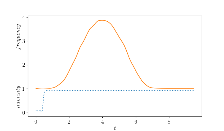
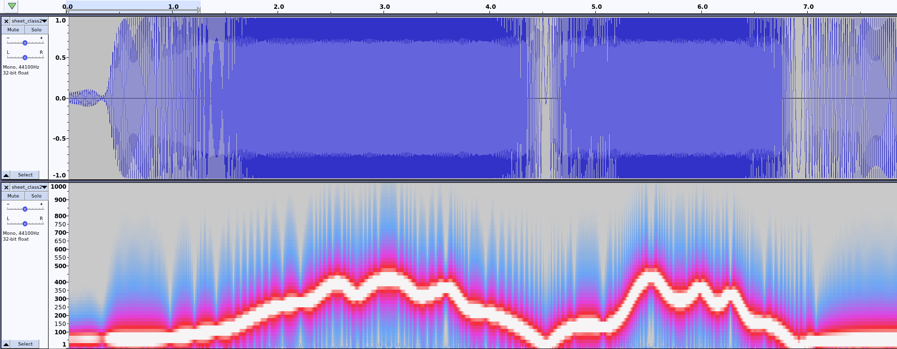
As a first example, we consider a three qubits system, with the following observables associated to intensity and frequency (fixed for the whole run):
| (5) | ||||
| (6) |
where are the projection operators, defined in Eq. (3). In this case, the intensity can be easily controlled by acting on the rightmost qubit register, for example by applying or , while the first two registers from the left are associated to a frequency, which can take values from to .

For example, applying the following circuit evolution:
| (7) |
the behaviour in Fig. 2 is produced, where measurements are interpolated and then synthetized as in Fig. 3.
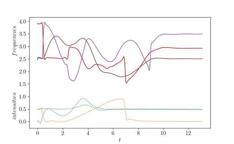
Fig. 4 and 5 show another example of qeyboard dynamics, again for a three qubits system, but with (non mutually commuting) Hermitian operators associated to intensities and frequencies for three sounds. The qeyboard-driven circuit evolution and the set of observables used in this case are more complicated, so we will not put the specific details of its generation here, but it should be nevertheless possible to appreciate the degree of customizability and expressivity which can be realized using this paradigm.
3 The sound of the Ising model
In this section we explore how to use physical systems to play quantum music. To this end we will employ the spectrum and other properties of a quantum system; here we consider the Ising model as a convenient toy system. The energies of the spectrum will be used as frequencies and other quantities such as the magnetization can be used for the intensites. These principles can be actually applied to many other physical systems, which would supply a very broad portfolio of sounds and eventually quantum music. The reason is that physical quantum systems can have very different properties showing a variety of phases and corresponding phase transitions.
The Ising Model is a simple statistical mechanical system, demonstrating of it serving as a microscopic model for magnetism exhibiting a quantum phase transition from unmagnetized to a magnetized phase. It consists of discrete two-valued variables that represent the two possible states ( or ) of magnetic dipole moments, or ”spin”. These spins are defined on a lattice and they interact with their nearest neighbours. The Hamiltonian of the system has two terms
| (8) |
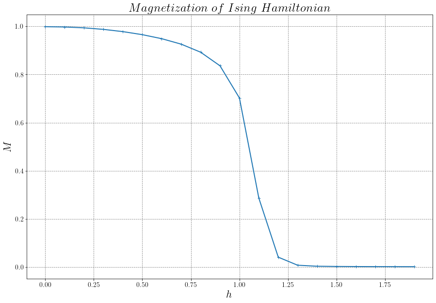
the first describes the interaction between neighbouring spins: if , neighbouring spins prefer to be aligned ( or ), which denotes a ferromagnetic behaviour. If , the preferred combination is anti-aligned (), leading to an anti-ferromagnetic behaviour. The second term represents the action of an external magnetic field with amplitude , which endows an energy advantage to the spins aligned to the magnetic field. If the value of is sufficiently large, i.e. , the Ising model undergoes a phase transition where the fluctuations of the spins increase and interesting physics starts to happen. Here also the magnetization, defined in Sec. 3.1.3, decreases sharply as a function of the external magnetic field. It is the goal of this section to use the properties of the Ising system to generate also interesting quantum sounds and even quantum music.
The idea is to use a variational approach, such as the Variational Quantum Deflation algorithm [5] (see Sec. 3.0.1) to find pairs of eigenvalues and eigenvectors(, ) of the Ising Hamiltonian, and then convert the properties of the system into audible sounds.
3.0.1 Variational Quantum Algorithms
The Variational Quantum Eigensolver [6] uses a variational technique to find the minimum eigenvalue of the Hamiltonian of a given system. An instance of VQE requires a trial state (ansatz), and one classical optimizer as summarized in Fig. 6.
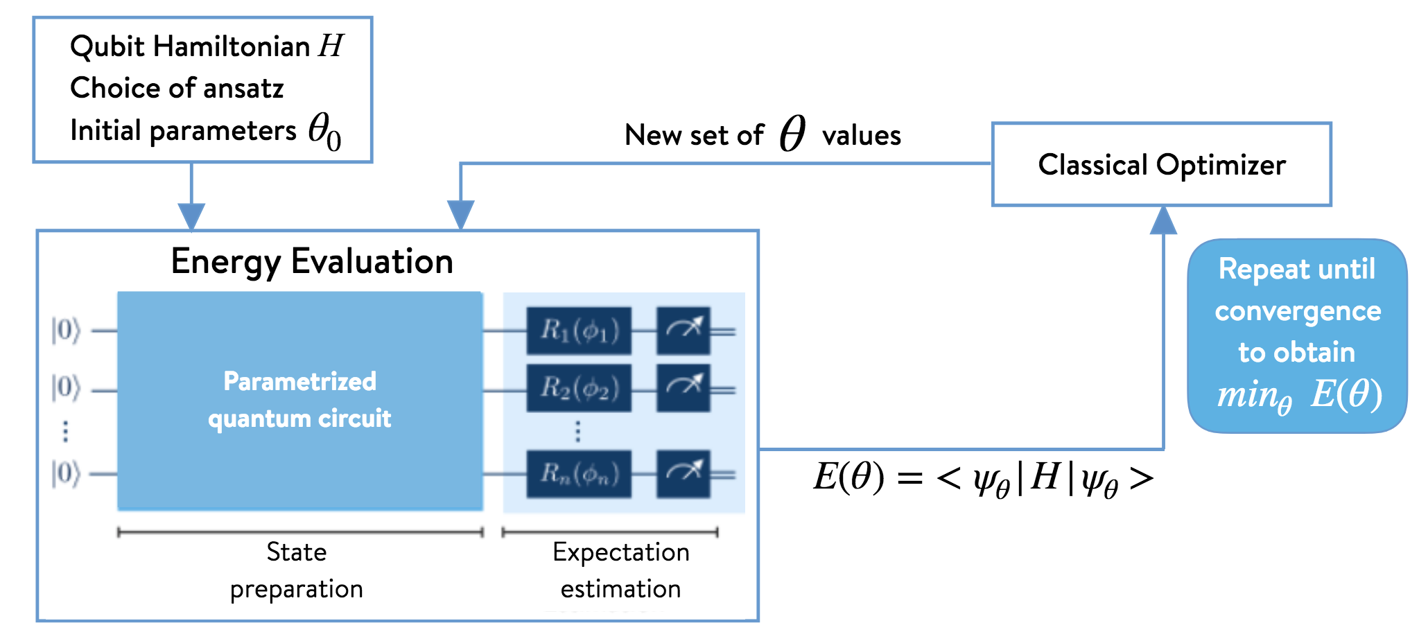
The ansatz is varied, via its set of parameters , generating a state which allows to measure the energy as the expectation value of the Hamiltonian, . The classical optimizer then gives back a new set of parameters for the next computation of the energy. This procedure is repeated until convergence to the true minimum of the expection value is found.
The VQE can be generalized also for computing excited states, for which the Variational Quantum Deflation (VQD) algorithm is used. The method has the following steps:
-
1.
Apply the VQE method and obtain optimal parameters and an approximate ground state .
-
2.
For the first excited state define a Hamiltonian:
(9) where is a real-valued coefficient.
-
3.
Apply the VQE approach to find an approximate ground state of .
-
4.
This procedure can be repeated for higher eigenstates.
3.1 How to play a quantum system
The aim of this section is to describe different possibilities for extracting sounds from a quantum physical system. By applying variational techniques we can get access to the observables of a quantum theory at the end of the minimization process and convert them to sounds. We can also measure the observables during the optimization itself and thus ‘play’ quantum music running the VQE or the VQD algorithms.
Most of these techniques can be generalized to an arbitrary Hamiltonian, such as the one of Quantum Electrodynamics, or even more intricate systems from condensed matter or high energy physics.
3.1.1 Convert energy eigenvalues into frequencies
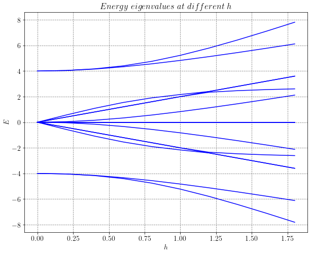
The first approach is to apply the VQD algorithm, compute the energy eigenvalues and convert them to audible frequencies. To this end a suitable interval of the energies is chosen for a given value of the coupling . Using as ‘time’ variable, we can follow the behaviour of the corresponding frequencies and play them through an output device. Fig.7 shows the dynamics of the whole energy spectrum (16 eigenvalues) and can be naturally interpreted as a spectrogram.
3.1.2 Use the callback results
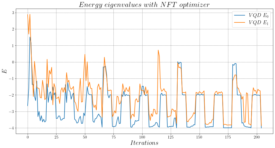
With this technique, the results for the ground state energy (or generic ) are collected during the VQD minimization with the NFT optimizer [8]. The energies are measured now in each step of the optimization procedure and again converted into frequencies. As can be seen in Fig. 8, the highly oscillatory behaviour of the energy values can be translated into frequencies. These oscillations are typical of the NFT algorithm but the detailed evolution depends on the physical quantum system under consideration. Playing the frequencies of this hybrid quantum/classical approach can lead to very interesting sounds.
3.1.3 Exploring how the sound changes across the phase diagram
With this method we include the magnetization as an observable measured in the ground state and which is defined as
| (10) |
In Fig. 9 we can see that for small the magnetization is equal to one, this corresponds to a ferromagnetic222Materials with a strong magnetization in a magnetic field. They can turn into permanent magnets, i.e. have magnetization in the absence of an external field. system. When increases, the magnetic term becomes more relevant and eventually the system reaches a paramagnetic333Materials with a weak induced magnetization in a magnetic field, which disappears when the external field is removed. behaviour, with . In particular, we can observe a quantum phase transition when .
The definition of the magnetization in Eq. (10) can be generalized for higher excited states
| (11) |
These eigenstate-dependent magnetizations can be related to the intensity of the sound of the corresponding frequency, defined by the -energy eigenvalue .
4 Summary and outlook
In this chapter we have discussed two approaches to generate sounds through quantum devices based on the circuit model. The first idea is to use the quantum computer as an instrument. Here we use a real time evolution and manipulate the quantum circuit through a (quantum-)keyboard. Measurements during the time evolution are performed to make them audible. The ideas that we described for a quantum instrument are open for customization by the user at different stages of the pipeline and allow for a high degree of flexibility.
The second idea is to use quantum physical systems for generating sound and therefore to be able to actually listen to a true quantum system. Here we followed the approach of assigning the role of ‘time variable’ to some parameter of the model under consideration. In particular, in the case of the here discusses Ising model, the external magnetic field was chosen. Frequencies can then be computed from the energy eigenvalues and intensities from the magnetization measured in the corresponding eigenstates. In our opinion, using quantum systems to generate sound and eventually quantum music can lead to very interesting effects since such quantum models describe often very complex phenomena and phase diagrams with intricate physical properties. In addition, they exhibit phase transitions where large fluctuations can occur with strong correlations. We believe that these chracteristics of quantum systems can be harvest through the quantum mechanical principles of superposition and entanglement possibly leading even to new directions in music.
Some resources (figures and sound files) for the examples that we discussed in the previous sections can be found in [9].
Our first step to generate quantum music presented in this chapter manipulates only frequencies and intensities which can be obtained through measurements of specific Hamiltonians or observables such as the magnetization. Our approach can be generalized to also generate tones and even more complicated music properties.
References
- [1] J. Preskill, “Quantum computing in the NISQ era and beyond,” Quantum, vol. 2, no. July, pp. 1–20, 2018.
- [2] V. Putz and K. Svozil, “Quantum music,” Soft Computing, vol. 21, pp. 1467–1471, Mar. 2017.
- [3] E. R. Miranda, “Quantum Computer: Hello, Music!,” arXiv:2006.13849 [quant-ph], June 2020. arXiv: 2006.13849.
- [4] E. Miranda, Computer Sound Design: Synthesis Techniques and Programming. 01 2002.
- [5] O. Higgott, D. Wang, and S. Brierley, “Variational Quantum Computation of Excited States,” Quantum, vol. 3, p. 156, July 2019.
- [6] A. Peruzzo, J. McClean, P. Shadbolt, M.-H. Yung, X.-Q. Zhou, P. J. Love, A. Aspuru-Guzik, and J. L. O’Brien, “A variational eigenvalue solver on a photonic quantum processor,” Nature Communications, vol. 5, no. 1, p. 4213, 2014.
- [7] http://openqemist.1qbit.com/docs/vqe_microsoft_qsharp.html.
- [8] K. M. Nakanishi, K. Fujii, and S. Todo, “Sequential minimal optimization for quantum-classical hybrid algorithms,” Phys. Rev. Research, vol. 2, p. 043158, Oct 2020.
- [9] https://github.com/QC-DESY/qeyboard_and_isingsound_resources.