An Efficiency-Based Power Management Strategy for an Isolated Microgrid Project
Abstract
The microgrids design for remote locations represents one of the most important and critical applications of the microgrid concept. It requires the correct sizing and the proper utilization of the different sources to guarantee the economical feasibility and the reliability of the supply. This study illustrates an efficiency-based power management strategy, designed for an undergoing microgrid project, where the sizing process of the resources (diesel generators, battery energy storage system, and PV plant) is obtained using a mixed-integer optimization algorithm. The proposed power management strategy guarantees the efficient exploitation of the power sources, which is one of the key elements of the optimal sizing process, being naturally included in the definition of the energy cost functions. The effectiveness of the power control strategy is validated by means of quasi-dynamic simulations on the complete microgrid model, where sources are defined by the optimal problem solution, while the cabling (size and length) and the main switchboards location reflect the expected system layout. Results obtained from the simulation of the microgrid electrical system include losses, and allow to verify and to highlight the desired quantities, such as the quality of supply at each busbar (voltage magnitude), and the state of charge of the energy storage system.
Index Terms:
efficiency, energy storage, isolated microgrid, optimal sizing, power management system.I Introduction
In the last years the energy sector has undergone a tremendous change. A wave of growing demography in emerging economies, tightening regulatory pressures in developed economies, advancements in technology and new business models have all supported a long-lasting transformation.
The spread of distributed energy resources, especially photovoltaic and wind, has changed radically the electrical system. Before the advent of distributed generation, the energy was produced in a few large thermal, hydro or nuclear plants and it was transmitted and distributed to the load in a radial and unidirectional power flow. After the coming of DG, the electrical system must face with lots of little conventional and renewable distributed generators. Modern power systems are called to manage the bidirectional power flows and the spread of renewable generation, which has the main characteristic of being stochastic and not dispatchable [1]. This is a significant challenge when trying to guarantee the balance between load demand and power generation. This problem is much more important when the size of the grids shrinks as distribution systems move from a centralized paradigm towards a local, decentralized, and potentially islanded operation [2]. Four major trends are at the foundation of this recent evolution and will continue to play in the decades ahead: i) diffusion of DERs; ii) a strong commitment to increase energy efficiency; iii) digitalisation of the grid; and iv) energy storage development.
All these factors made the big centralized electrical system move to more decentralized and local ones; in this scenario microgrids are one of the most interesting challenges [3]. A microgrid is an energy supply network built around local power and (usually also) heat generation facilities [4], and it is designed to operate autonomously or in parallel with a national grid [5]. In order to foster economy growth, it is vital to develop local microgrids capable of generating and distributing electricity in many contexts, such as islands, and remote areas. The same solution provides the additional opportunity to benefit from clean, renewable energy sources [6, 7]. A microgrid is typically made up of: i) renewable energy sources (solar, wind or biomass); ii) fossil fuel energy sources (conventional sources) to ensure grid stability; iii) energy storage solutions (batteries, hydrogen storage, mechanical storage, etc.); and iv) a low-voltage distribution grid [8].
Microgrids have become competitive as a result of technological progress and decreasing prices of certain key components, including photovoltaic panels, batteries and control systems [9], together with the implementations of energy management strategies [10, 11]. In order to properly manage the installed units and the power flows during operation, the microgrid central controller (MGCC) has a fundamental role in both islanded and grid connected operating conditions [12, 13]. It is also of paramount importance to properly design the microgrid, setting the right sizes of the various equipment [14], especially the battery energy storage systems [15].
The aim of this paper is twofold. From the one hand it describes a mixed integer linear programming-based methodology to optimally design the microgrid. On the other hand, it describes a control methodology of the microgrid in which the BESSs are the grid-forming units. The rationale of this choice is the fact that the main scope of the MGCC is to reduce the costs from fossil-fuel-based generation and to maximize the exploitation of the energy from renewable sources. The contribution of this paper is that the decision on the power management is subject to an efficiency-based logic and the round-trip efficiency of the BESSs is used as a threshold to determine whether or not the diesel generators should be activated or switched off.
The paper is organized as follows. Section II describes the optimization algorithm along with the obtained configuration. Section III is devoted to the description of the power management system (PMS) and the results of a 1-year quasi-dynamic simulation of the microgrid are analyzed in Section IV. Finally, conclusions are drawn in Section V.
II Microgrid Optimal Sizing
The optimal sizing is performed using a mixed-integer linear programming (MILP) formulation, presented in this Section. It is implemented in Matlab-AMPL environment, using CPLEX solver. The complete formulation is omitted in order to focus on the most innovative aspects of this work, but the reference model can be found in [16] (with due adjustments to unknown sizes of devices).
II-A Methodology
The sizing is performed on a single busbar microgrid. The main constraint is the classical electrical balance equation
| (1) |
where is the load power profile, and are the power profiles delivered by DG units and by the photovoltaic (PV) plant respectively, and is the power profile exchanged by the BESSs. A curtailment of the PV plant is allowed, though a priori could be not convenient, in order to avoid the oversizing of BESSs to guarantee the balance even in off-grid operation.
The objective function is composed by the capital expenditures for all the components to be installed, the operating expenses of diesel (fuel consumption and maintenance). Capital expenditure of photovoltaic plant and BESSs is surcharged in order to include maintenance costs, assumed to be proportional to rated capacity. A pay-back time of 8 years is imposed for the investments above. Thus, the object function can be written as
| (2) |
where the size of each device ( of DGs, and for energy capacity and power rating of storage devices and for PV) is weighted by the corresponding costs (, and , ), plus fuel consumption cost .
All the controllable devices are then modelled with proper constraints:
II-A1 Diesel generators
They must respect minimum and maximum active power limits, proportional to the (unknown) number of devices installed. Three discrete sizes of DGs (, , and , i.e., , , and ) can be chosen by the algorithm. Fuel consumption curve is a linear function of active power setpoint [17, 18], not just proportional to it, but with a y-intercept that leads to an hyperbolic efficiency curve. A binary variable to represent the on/off status of the device is necessary. In order to reduce the computational burden and considering the fact that the aim of this phase is the planning, start up cost, ramp limits, and minimum up and down times are neglected.
II-A2 Storage systems
They are more complex: in addition to power limitations, they require state of charge (SOC) computation (thus, an inter-temporal constraint), which is bound to stay between 30% and 90% of the (unknown) rated capacity. Two different values of C-rate (the ratio of rated active power to the nominal energy, i.e., the maximum constant power that the battery can exchange in an hour) are available, 1C and 0.5C, and the algorithm chooses the most appropriate, in terms of objective function minimization. Charge and discharge efficiencies are modelled according to [19] (respectively 0.87 and 0.86), using binary variables to identify charge and discharge states.
II-A3 Photovoltaic plant
Actually this component is not controllable by the system: its production, , is just proportional to input profiles (described in next subsection). Curtailment power is a slack variable, positive and bound to be always smaller than .
II-B Inputs
The main input of the problem is the electrical demand to be supplied. Typical load profiles have been developed in order to simulate a 10-year horizon, combining typical daily and annual profiles for a resort, scaled on a -rated load, with random fluctuations around average trends.
Real measurements of local solar irradiance (in a time span 2005–2014) are used and converted into the expected PV power production according to [20]:
| (3) |
where is the global horizontal irradiance, is the total rated power (unknown here, thus the production is scaled proportionally to this value), is the (constant) irradiance at standard test conditions, and are the efficiencies of the panels and inverter, and is a degradation coefficient, well detailed in [20].
II-C Results
Optimal sizes obtained with the proposed formulation are:
-
•
PV =
-
•
BESS = /
-
•
Two -rated and one -rated diesel generators.
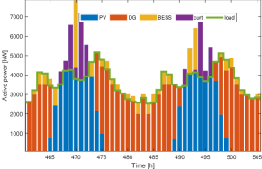
In Figure 1, a focus on two daily power profiles of the microgrid components is offered, highlighting the correct match of demand (green line) with the mix of production, storage and curtailment. BESS power is to be considered an absorption (charging) when it is above the load line, or a power injection (discharging) when below that line.
The obtained configuration is compared with that obtained by HOMER (Hybrid Optimization of Multiple Energy Resources) software using the same economical and technological assumptions. The resulting configuration is:
-
•
PV =
-
•
BESS = /
-
•
Two -rated, one -rated and one -rated diesel generators.
Thus, it can be stated that a significant reduction is reached by the proposed technique. Even if it suggests less and smaller devices, it is verified that all the constraints are met throughout the whole simulated horizon and the overall system is more efficient.
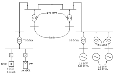
II-D Grid layout
The grid topology is depicted in Figure 2. It has been defined with the aim to respect geographical constrains of the prospected location (an island), while ensuring reliable supply to loads, by decoupling the two sets of generators (PV, and DGs). Transformers, lines and electrical machines have been modeled and characterized using parameters from literature and technical data sheets, in order to reproduce a valid simulation model. The microgrid has been implemented in DIgSILENT PowerFactory.
III Power Management Strategy
The power management strategy has been designed to satisfy the operational limits of components, while maximizing the energy production efficiency. The consolidated microgrid control system architecture refers to a well known hierarchical structure [21, 22], where local controllers are coordinated by the MGCC. The MGCC implements the PMS that has the main task to ensure the power availability at each time, by managing generators in order to avoid black-out occurrences and to maintain the quality of the supply at load busbars. The PMS ensures adequate primary reserve, switches on and off generators and realizes the power sharing among controllable generating units.
III-A Local controllers
Each power source is equipped with its own local controller. BESS represents the grid forming unit, and it regulates system frequency and voltage magnitude at the generation busbar. It can be modeled with a voltage source inverter (VSI) [23] and in quasi-dynamic simulations is the slack node.
DGs adopted in this study are controlled as constant power factor sources. Their representation in quasi-dynamic simulations corresponds to a PQ node.
The PV plant is a grid feeding unit, well described by a current source inverter (CSI) model, whose power injection is driven by the solar irradiance. The PV plant can be only partially controlled and offer very limited regulation capabilities to the system (i.e., operation at constant power factor and power curtailment functionality). Its representation for quasi-dynamic simulations corresponds to a PQ node.
III-B Power Management System
The essential role of a PMS for storage-based isolated microgrids is to maintain the SOC of the BESS within the operational limits. While the optimization procedure has the perfect knowledge of load and PV production profiles over the entire time horizon, the PMS works without any prior information concerning future power absorption and production. Energy management functionalities based on forecasting tools are not included in this work, being this power management algorithm designed to be implemented on-board commercial PLC or intelligent breakers with limited computational capabilities.
The first task of the PMS is to define, for each control interval, the available charging () and discharging () powers of the BESS, according to the current SOC value, as shown in Figure 3.
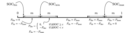
In Figure 3 and are the minimum and maximum SOC values, defined as
| (4) | |||||
| (5) |
where the margin value allows the battery to maintain a residual amount of regulating energy ensuring the primary reserve. The limit value is equal to 0.2, and represents the usual lower operational limit of Li-ion-based storage systems. Once the margin is decided by the microgrid operator, the derating power () is automatically defined as
| (6) |
where:
-
•
is the nominal energy of the BESS;
-
•
is the time control interval of the PMS (in );
-
•
is the global charging/discharging efficiency.
The derating value corresponds to the active power production (or absorption) that allows to respect the operational limits of the battery, even if the actual state of charge is close to either upper or lower bounds.
It is important to notice that when the SOC is within the thresholds and , the discharging power value depends also on the variation of the SOC itself (). This peculiarity allows the PMS to avoid the interruption of a charging process while ensuring the full discharging capability of the battery when it provides power to the system.
The proposed power management algorithm is based on a state-space representation of the microgrid operating conditions. The PMS does not control the active power reference of the BESS, which is the grid-forming unit, but controls the diesel generators set-points. The key control variable of the power control strategy is given by
| (7) |
and is the difference between the load power and the total power production availability (given by the sum of the power produced by the PV plant and the available power of the BESS, ). If the control variable is negative, at least one diesel generator has to be switched on.
The PMS has been designed to maximize the efficiency of power production. For this reason a further aspect has been analyzed and included in the algorithm. Figure 4 shows the global efficiency curve of the diesel power station (), assuming to operate generators with the same incremental costs, which is the optimal solution of the multiple-machine dispatching problem. The blue line shows the round-trip efficiency curve () of the energy produced by the DGs, and provided by the BESS through a double conversion stage (charging and discharging). The round-trip efficiency is
| (8) |
where:
-
•
is the maximum DG efficiency;
-
•
is the global charging efficiency of BESS;
-
•
is the global discharging efficiency of BESS.
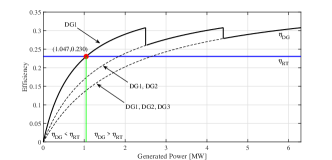
If the power requested to the DG is lower than the point of intersection between the two efficiency curves (at ), then it is convenient to utilize the diesel generator at the nominal power, i.e., the maximum continuous rating (MCR), and to store the energy excess in the battery.
Table I illustrates the operational states of the PMS, i.e., the operating condition of the microgrid.
![[Uncaptioned image]](/html/2203.16228/assets/x5.png)
IV Long-Term Simulations
In order to validate the proposed power management strategy quasi-dynamic simulations have been carried out. These simulations explore a one-year time span of operation of the microgrid depicted in Figure 2 through subsequent power flows in which the SOC is used as a “state variable” throughout the whole simulation. The parameters are reported in Table II.
| Parameter | Value |
|---|---|
| margin () | 0.05 (5%) |
| 0.9 | |
| 1 | |
| Expected grid losses () | 2.6% |
| Voltage set-point () | 1.025 p.u. |
The efficiency of the BESS, , i.e., the global charging/discharging efficiency of the storage system, including auxiliary loads, inverter, battery and filter losses is
| (9) |
The values in (9) are extracted from a real measurement campaign [19], and have been adopted for the current study case.
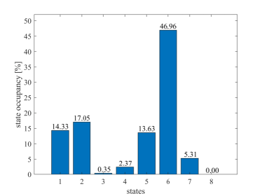
In Figure 5 the occurrence of each state (as defined in Table I) is reported. It describes the amount of time the microgrid spend in each of the eight states. It can be clearly noticed that the overload state (no. 8) is never visited. Moreover, the most probable state is no. 6, in which only two DGs are active.
V Conclusion
This work presented the optimal sizing of an islanded microgrid and its management strategy. This strategy is based on an efficiency logic aimed to optimize the energy stored in the BESS and the energy produced by the renewable energy sources by minimizing the intervention of the fossil-fuel-based generators. The management strategy has been tested (and its effectiveness has been validated) by means of a one-year quasi-dynamic simulation. Further work will be carried out to prove the PMS capability under different load profiles and component sizing.
References
- [1] S. Grillo, M. Marinelli, S. Massucco, and F. Silvestro, “Optimal Management Strategy of a Battery-Based Storage System to Improve Renewable Energy Integration in Distribution Networks,” IEEE Trans. Smart Grid, vol. 3, no. 2, pp. 950–958, Jun. 2012.
- [2] B. C. Phan and Y.-C. Lai, “Control Strategy of a Hybrid Renewable Energy System Based on Reinforcement Learning Approach for an Isolated Microgrid,” Applied Sciences, vol. 9, no. 19, 2019.
- [3] J. A. Peças Lopes, A. Guimarães Madureira, and C. C. L. Monteiro Moreira, “A view of microgrids,” Wiley Interdisciplinary Reviews: Energy and Environment, vol. 2, no. 1, pp. 86–103, 2013.
- [4] N. Stevanato, L. Rinaldi, S. Pistolese, S. L. Balderrama Subieta, S. Quoilin, and E. Colombo, “Modeling of a Village-Scale Multi-Energy System for the Integrated Supply of Electric and Thermal Energy,” Applied Sciences, vol. 10, no. 21, 2020.
- [5] A. Cagnano, E. De Tuglie, and P. Mancarella, “Microgrids: Overview and guidelines for practical implementations and operation,” Appl Energy, vol. 258, p. 114039, 2020.
- [6] M. K. Kiptoo, O. B. Adewuyi, M. E. Lotfy, T. Senjyu, P. Mandal, and M. Abdel-Akher, “Multi-Objective Optimal Capacity Planning for 100% Renewable Energy-Based Microgrid Incorporating Cost of Demand-Side Flexibility Management,” Applied Sciences, vol. 9, no. 18, 2019.
- [7] I. Worighi, T. Geury, M. El Baghdadi, J. Van Mierlo, O. Hegazy, and A. Maach, “Optimal Design of Hybrid PV-Battery System in Residential Buildings: End-User Economics, and PV Penetration,” Applied Sciences, vol. 9, no. 5, 2019.
- [8] F. D’Agostino, S. Massucco, F. Silvestro, C. Bossi, A. Guagliardi, and C. Sandroni, “Implementation of a Distribution State Estimation Algorithm on a Low Voltage Test Facility with Distributed Energy Resources,” in 2016 IEEE PES ISGT Europe, 2016, pp. 1–6.
- [9] N. Hatziargyriou, A. Dimeas, N. Vasilakis, D. Lagos, and A. Kontou, “The Kythnos Microgrid: A 20-Year History,” IEEE Electrification Mag., vol. 8, no. 4, pp. 46–54, 2020.
- [10] Y. E. García Vera, R. Dufo-López, and J. L. Bernal-Agustín, “Energy Management in Microgrids with Renewable Energy Sources: A Literature Review,” Applied Sciences, vol. 9, no. 18, 2019.
- [11] S. Ahmad, I. Ullah, F. Jamil, and D. Kim, “Toward the Optimal Operation of Hybrid Renewable Energy Resources in Microgrids,” Energies, vol. 13, no. 20, 2020.
- [12] D. E. Olivares, A. Mehrizi-Sani, A. H. Etemadi, C. A. Cañizares, R. Iravani, M. Kazerani, A. H. Hajimiragha, O. Gomis-Bellmunt, M. Saeedifard, R. Palma-Behnke, G. A. Jiménez-Estévez, and N. D. Hatziargyriou, “Trends in Microgrid Control,” IEEE Trans. Smart Grid, vol. 5, no. 4, pp. 1905–1919, Jul. 2014.
- [13] M. M. A. Abdelaziz and H. E. Farag, “An Enhanced Supervisory Control for Islanded Microgrid Systems,” IEEE Trans. Smart Grid, vol. 7, no. 4, pp. 1941–1943, 2016.
- [14] N. Shirzadi, F. Nasiri, and U. Eicker, “Optimal Configuration and Sizing of an Integrated Renewable Energy System for Isolated and Grid-Connected Microgrids: The Case of an Urban University Campus,” Energies, vol. 13, no. 14, 2020.
- [15] G. Carpinelli, F. Mottola, D. Proto, A. Russo, and P. Varilone, “A Hybrid Method for Optimal Siting and Sizing of Battery Energy Storage Systems in Unbalanced Low Voltage Microgrids,” Applied Sciences, vol. 8, no. 3, 2018.
- [16] S. Massucco, P. Pongiglione, M. Saviozzi, F. Silvestro, P. Almaleck, and P. Serra, “Algorithm for Optimal Microgrid Operation and Control with Adaptable Constraints and Flexible Objective Function,” in International Forum on Research and Technologies for Society and Industry (RTSI), 2019.
- [17] D. De Serio, A. de Oliveira, and J. R. Sodré, “Effects of EGR rate on performance and emissions of a diesel power generator fueled by B7,” Journal of the Brazilian Society of Mechanical Sciences and Engineering, vol. 39, no. 6, pp. 1919–1927, Jun. 2017.
- [18] Homer Pro 3.13 User Manual, HOMER Energy LL, April 2019.
- [19] F. Conte, F. D’Agostino, P. Pongiglione, M. Saviozzi, and F. Silvestro, “Mixed-Integer Algorithm for Optimal Dispatch of Integrated PV-Storage Systems,” IEEE Trans. Ind. Appl., vol. 55, no. 1, pp. 238–247, Jan. 2019.
- [20] S. Massucco, G. Mosaico, M. Saviozzi, and F. Silvestro, “A Hybrid Technique for Day-Ahead PV Generation Forecasting Using Clear-Sky Models or Ensemble of Artificial Neural Networks According to a Decision Tree Approach,” Energies, vol. 12, no. 1298, Apr. 2019.
- [21] J. M. Guerrero, J. C. Vasquez, J. Matas, L. G. de Vicuna, and M. Castilla, “Hierarchical Control of Droop-Controlled AC and DC Microgrids–A General Approach Toward Standardization,” IEEE Trans. Ind. Electron., vol. 58, no. 1, pp. 158–172, Jan. 2011.
- [22] R. Jackson, S. A. Zulkifli, M. Benbouzid, S. Salimin, M. H. Khan, G. Elhassan, and E. Pathan, “A Comprehensive Motivation of Multilayer Control Levels for Microgrids: Synchronization, Voltage and Frequency Restoration Perspective,” Applied Sciences, vol. 10, no. 23, 2020.
- [23] J. Rocabert, A. Luna, F. Blaabjerg, and P. Rodriguez, “Control of Power Converters in AC Microgrids,” IEEE Trans. Power Electron., vol. 27, no. 11, pp. 4734–4749, Nov. 2012.