Near-Field Hierarchical Beam Management for RIS-Enabled Millimeter Wave Multi-Antenna Systems
Abstract
In this paper, we present a low overhead beam management approach for near-field millimeter-wave multi-antenna communication systems enabled by Reconfigurable Intelligent Surfaces (RISs). We devise a novel variable-width hierarchical phase-shift codebook suitable for both the near- and far-field of the RIS, and present a fast alignment algorithm for the RIS phase shifts and the transceiver beamformers. Indicative performance evaluation results are shown, verifying the effectiveness of the proposed approach in comparison with various benchmark schemes.
Index Terms:
Reconfigurable intelligent surfaces, beam management, hierarchical codebook, near-field regime, millimeter wave.I Introduction
The concept of programmable radio propagation environments [1, 2, 3, 4], and its potential for cost- and energy-efficient smart wireless networking, is lately gaining increased interest thanks to the technology of Reconfigurable Intelligent Surfaces (RISs) [5, 6, 7]. Due to their minimal hardware footprint, RISs are envisioned to coat objects in the wireless medium, offering new degrees of freedom for diverse communication, localization, and sensing improvements. However, their performance gain mostly relies on the availability of Channel State Information (CSI), which given the typically large number of reflecting elements (denoted, henceforth, by ) translates into a huge, and often unaffordable, CSI acquisition overhead [8, 9].
There exists already a remarkable amount of literature on Channel Estimation (CE) techniques for RIS-assisted wireless communications systems; see [10] for a recent overview. The two main CE categories, whose overhead does not scale with , exploit sparsity- and codebook-based schemes [11, 12]. In particular, the sparsity of the wireless channel in the angular domain was exploited in [11] to design a CE algorithm, whose overhead scales with the number of dominant propagation paths of the wireless channel. In contrast, in [12], the authors proposed to estimate the end-to-end Base-Station (BS) to RIS to Mobile User (MU) channel only for a limited number of RIS phase-shift configurations drawn from a codebook. The presented small-sized phase-shift design led to CE overhead scaling with the codebook size. In [13], a multi-beam training method using the codebook approach of [14] was proposed, according to which the RIS elements were divided into sub-surfaces, with each realizing a distinct codebook intended for a distinct MU. A similar approach was considered in [15], where the authors focused on minimizing beam request collisions for MUs belonging in similar impinging angles. In [16], a hierarchical beam searching scheme for RIS-assisted THz communications was presented, which relied on RIS phase-shift codebooks for efficient ternary-tree search. Random-beamforming-based maximum likelihood estimation of the parameters associated with the Line-Of-Sight (LOS) component, while treating other non-LOS components as interference, was proposed in [17]. In [18], an uplink beam training scheme was designed for multi-antenna multicast systems, where the RIS was used as a component of the transmitter. By exploiting the inherent sparse structure of BS-RIS-MU cascade millimeter-Wave (mmWave) channels, in [19], multi-directional beam training sequences were presented, while the beam training problem was formulated as a joint sparse sensing and phaseless estimation problem. In [20], a hierarchical RIS phase-shift configuration design was presented, together with an algorithm that exploits the angular-domain channel representation, to maximize the MU achievable rate. CE with hierarchical beam searching was also considered in [21], focusing on the channel between the RIS and MU.
All aforementioned works, similar to most available codebook-based CE schemes for RIS-assisted wireless systems, consider signal propagation in the far-field of the RIS. However, for high-frequency scenarios incorporating large RISs for confronting high pathloss attenuation, and thus, offering cost- and energy-efficient coverage extension, the wireless communication will often take place in the near-field of RISs. Motivated by this fact, in this paper, we present a beam management framework for RIS-enabled mmWave multi-antenna communication systems. Capitalizing on the wide illumination approach recently designed in [22] for low-overhead CE in mobile scenarios, we devise a variable-width hierarchical phase-shift codebook for near-field communications. Our simulation results for a typical mmWave communication system confirm that the proposed hierarchical beam management algorithm is able to successfully find a suitable RIS phase-shift configuration for extremely large IRSs (with reflecting elements) with only a few pilot transmissions (i.e., ), while achieving performance close to that of a benchmark that assumes the availability of full CSI (i.e., channel coefficients).
Notation
Vectors and matrices are denoted by boldface lowercase and boldface capital letters, respectively. is ’s Hermitian transpose, () is the identity matrix, and () is an matrix of zeros. denotes ’s Euclidean norm, represents the complex number set, is the expectation operator, and indicates a complex Gaussian random vector with mean and covariance matrix . Finally, is the imaginary unit.
II System and Channel Models
II-A System Model
We consider a communication system model comprising one BS equipped with antenna elements, one RIS consisting of phase-tunable unit cell elements with inter-element spacing and on the - and -axis, respectively, indexed by and , and one MU with antennas. In the downlink communication direction, the baseband received signal, , at the MU antenna elements can be mathematically expressed as follows:
| (1) |
where denotes the transmitted signal from the BS, such that with being the total transmit power budget of the BS, and represents the Additive White Gaussian Noise (AWGN) at the MU receiver. We assume linear precoding, i.e., , where is the BS precoder and denotes the complex-valued data or pilot symbol; in the former case, its chosen from a discrete modulation set. The diagonal matrix in (1) is defined as , where each (with ) is the phase shift applied by the -th RIS unit cell element and is a unit-less factor resulting from each element with being the wavelength [12]. Furthermore, , , and denote the channel matrices for the BS-MU, BS-RIS, and RIS-MU links, respectively. We also assume that the MU is capable of realizing fully digital combining of the received signal . This combining operation is accomplished by the vector and we assume that .
II-B Near-Field Channel Model
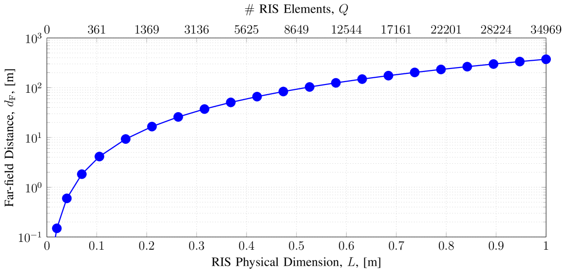
A pragmatic criterion that quantifies the transition between the far-field and near-field regimes is the critical distance, beyond which the maximum phase error caused by the assumption of the linear phase wavefront in the far-field does not exceed [23, Ch. 4]. We define this distance as , with and being the largest dimension of the RIS in meters and its electric size (unit-less), respectively. Figure 1 illustrates as a function of the RIS physical size (i.e., ) and (i.e., where ). We note that increases with frequency for a given (or equivalently the RIS physical dimension), but decreases with frequency when (or equivalently the RIS electric dimension) is kept fixed.
The involved wireless channels are modeled as collections of propagation paths. Assuming paths for the BS-RIS link, the channel gain between the -th antenna (with ) at the BS and the -th element at the RIS, having distance in the -th path, can be expressed as:
| (2) |
where and denote the channel pathloss and small-scale fading of the BS-RIS link, respectively. Similarly, the components of the BS-MU and RIS-MU channel matrices are given by and , respectively, where the parameters are defined analogously; for example, is the pathloss of the -th path in the RIS-MU channel. In this paper, we consider cases where the BS-RIS and RIS-MU links have dominant LOS channel components (denoted by index ) and their distances are below , and the direct BS-MU link is severely blocked. For the latter, we incorporate a strong loss factor in .
III Proposed Beam Management Framework
The first objective of this section is to design a set of RIS phase-shift codebooks, denoted by , where and each level’s codebook , with , consists of RIS phase shifts with . We employ the near-field phase-shift design in [22] for constructing the hierarchical codebooks in this paper. In particular, we characterize each RIS phase-shift codeword in terms of the Generalized Radar Cross Section (GRCS) defined in [24], which is used to derive the free-space end-to-end pathloss of the RIS-enabled link, denoted by , according to [24, Lemma 1] (we have normalized [24]’s definition to in order to get a unit-less quantity):
| (3) |
where and are the free-space pathlosses of the BS-RIS and RIS-MU LOS links, respectively. The value of depends on the RIS phase-shift configuration value as well as the relative positions of the BS and MU with respect to the RIS.
Capitalizing on the proposed near-field hierarchical codebook for the RIS, we devise an RIS profile and BS/MU beamforming alignment algorithm for establishing an RIS-enabled end-to-end multiple-input multiple-output channel according to a predefined performance objective.
III-A Near-Field Hierarchical Codebook Design
A convenient way to represent the RIS GRCS in the near-field case is to model the BS as a point source, which leads to the following expression for appearing in (3):
| (4) |
where , , and , denote the position of the BS, observation point, and the -th RIS element, respectively. In contrast to the far-field case where the BS, MU, and the channel scatterers may belong to a wide range of angles of arrival and departure [12], in the near-field case, it is more reasonable to focus on only the BS-RIS and RIS-MU LOS paths, where the RIS aims to illuminate the MU in a closely placed blockage area . Therefore, our objective is to design a finite set of phase-shift configurations which together are able to illuminate the entire blockage area. For simplicity, we assume that the blockage area is a rectangular one with its center at the point , length , width , and the same height for all points, i.e., .
The problem of wide near-field illumination was recently treated in [22], but not for a hierarchical codebook design. Exploiting this result, we propose the RIS phase-shift profile:
| (5) | |||||
where represents the center of the RIS and denotes a mapping from , to the points on the blockage area , which is given as follows:
| (6) |
with and , where , . In (6), the term determines the center of illumination by the codeword , and the parameter controls the illumination’s width, where specifies the degree of overlapping illumination among neighboring codewords. Note that, while the width of the illuminated area along the -axis is mainly due to the phase shifts applied by the RIS along the -axis, the width of the illuminated area along the -axis is mainly due to the phase shifts applied by the RIS along the -axis. The discritization of and the value of are chosen such that the entire blockage area is covered via RIS phase-shift configurations.
Level 4 ()
Level 3 ()
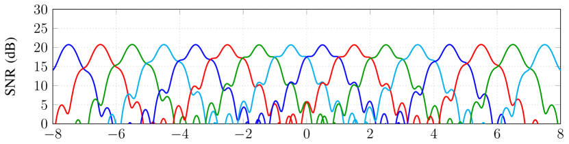
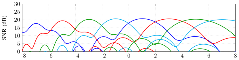
Level 2 ()
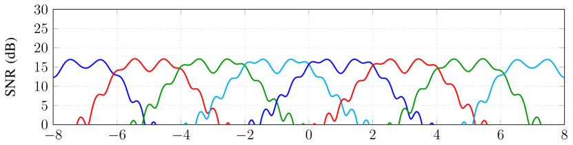
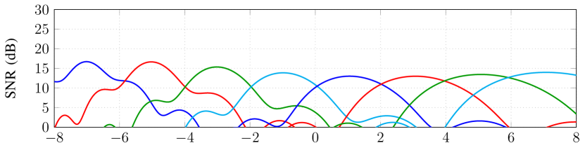
Level 3 ()
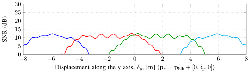
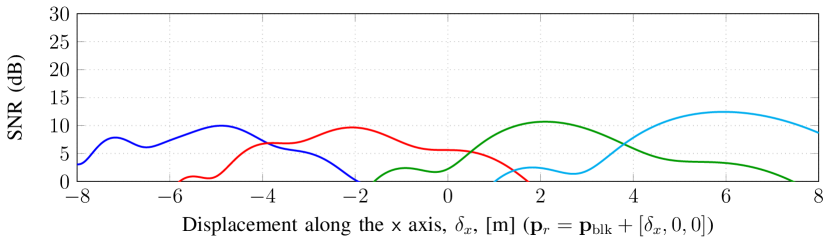
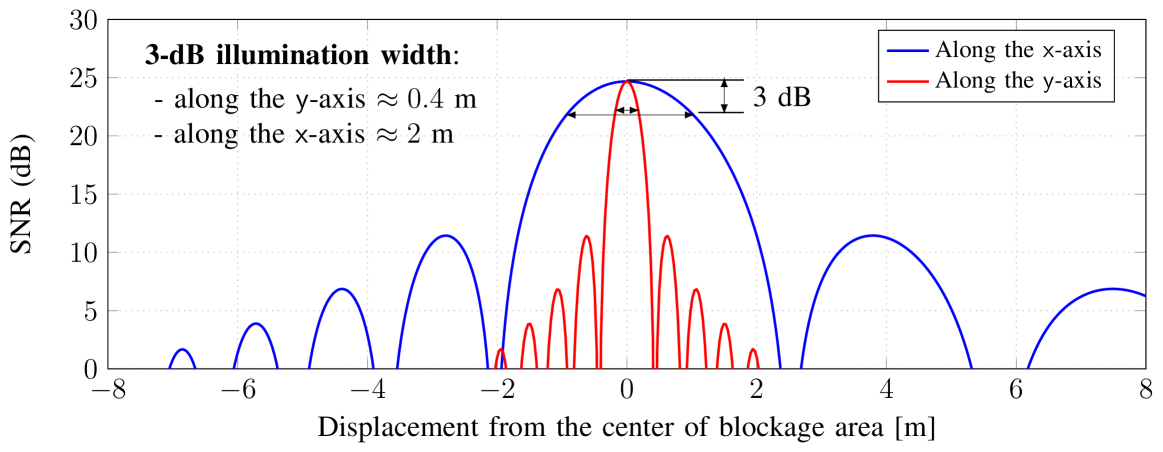
It is crucial to notice that the values of ranges and are not necessarily identical due to the different illumination widths that they can generate along the and -axes, respectively. To show this feature, we assume that the RIS focuses on point via the following focusing phase-shift profile:
| (7) |
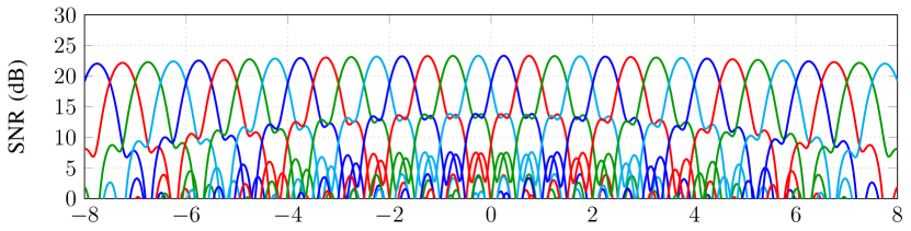
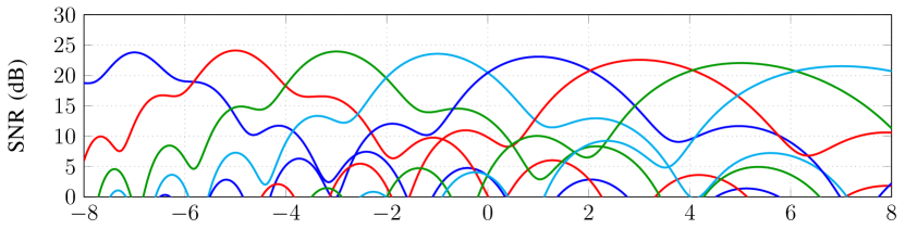
This leads to the maximum GRCS at point . In Fig. 2, we plot the Signal-to-Noise Ratio (SNR), defined as , of the RIS-enabled link as a function of the displacement from along the -axis (denoted by ) and the -axis (denoted by ) (i.e., and , respectively). As shown in the figure, the power distributions along the - and -axes on the blockage area exhibit a completely different behavior. In particular, for a given and assuming that the blockage area is in front of the RIS (i.e., ), it is observed that the spread of the beams across the -axis is relatively regular. However, this is not the case for the -axis, where the beams become wider as we move away from the RIS. This is due to the fact that the wave propagates along the -axis, which further increases the spread of the beamwidth. This implies that for narrow illumination, should be chosen larger than in order to cover the entire coverage area. Using this intuition, Fig. 3 illustrates an example multi-level codebook design using (5), which includes levels with respective sizes for levels , and (i.e., codebook sizes , and , respectively). We see from Fig. 3 that for a large RIS with , the proposed codebook with size achieves a peak illumination SNR of dB at which is within only dB of the maximum SNR achieved via full focusing, see Fig. 2.
III-B RIS Phase-Shift Management
We consider simple BS precoding and MU combining designs and focus mainly on the design of RIS phase-shift profiles. Recall that the RIS is deployed in ways such that it has strong LOS connection to the BS and MU. Since the BS and RIS are fixed-position nodes, we consider a fixed precoder that is designed to focus on the RIS center. However, the MU may not know the position of the RIS, and hence, we assume that it can apply a set of combiners (denoted by ), choosing the one maximizing the received signal power. By denoting as the RIS phase-shift profile using the -th codeword in the -th level codebook , the instantaneous SNR at the MU is calculated as follows:
| (8) |
where we assumed . During each SNR measurement, the BS sends pilot symbols, the RIS sets one phase-shift configuration , and the MU empirically computes . Then, for each level of the RIS codebook, the MU reports the index of the phase shift with the maximum SNR, denoted by , back to the RIS controller using a feedback control link. This is mathematically expressed as:
| (9) |
where is the reduced set of phase-shift indices used at the -th codebook level. In particular, the RIS uses to determine to consequently narrow down the search in the next codebook level. Obviously, the codebook at the first level is not reduced, i.e., . The hierarchical RIS beam management is summarized in Algorithm 1.
IV Numerical Results and Discussion
The simulation setup uses the following parameters. A carrier frequency GHz and half-wavelength antenna element spacing at all nodes were adopted. In particular, the BS is equipped with a square array of antennas placed on the plane, with the center at . The RIS has a square aperture of size m (i.e., ) placed on the plane, with the center at . Although the proposed algorithm is valid for multi-antenna MUs, in the simulation results, we assumed in order to compare our algorithm with Benchmark 3 (full CSI), which is introduced later. The MU is located in a square blockage area of size parallel to the plane with center , and we set m. The blockage in the direct BS-MU link is modeled by an attenuation factor of dB. Moreover, in addition to LOS paths, we assume that there are non-LOS scattering paths in the BS-RIS, BS-MU, and RIS-MU links, i.e., , respectively. The positions of the channel scatters are randomly generated within volume . We assume dBm, noise spectral density dB/Hz, bandwidth MHz, and noise figure dB. The simulation results are generated for random realizations of the positions of the MU and the channel scatterers.
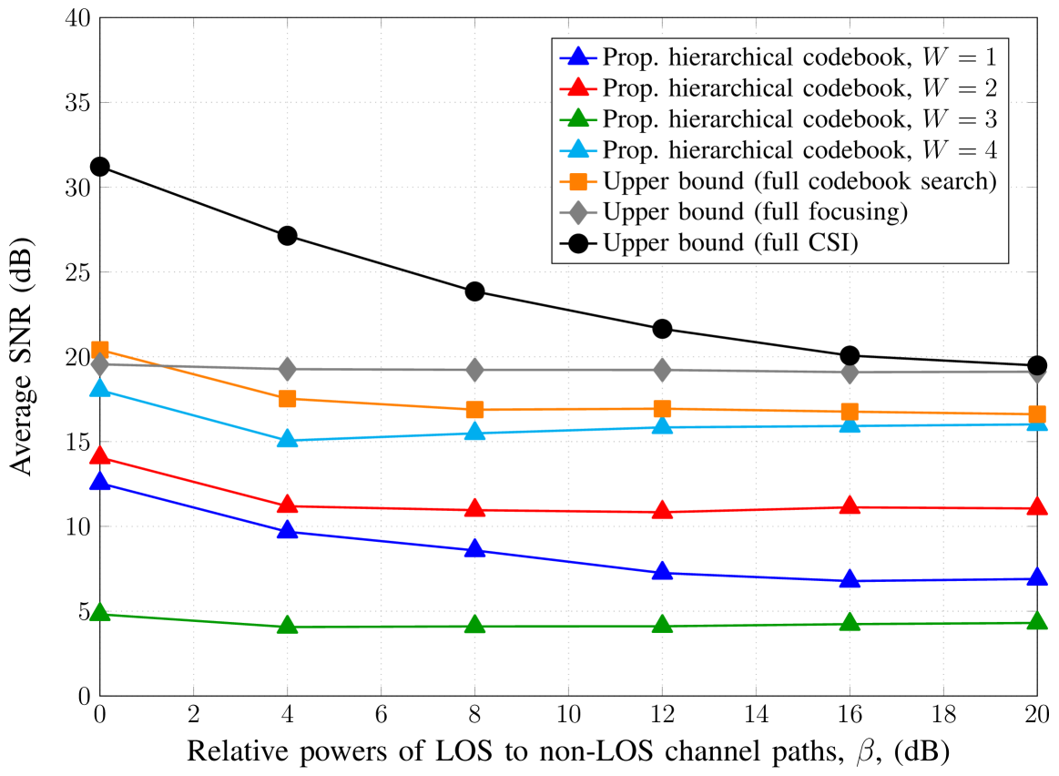
We use the four-level hierarchical RIS phase-shift codebook presented in Fig. 3. Therefore, the BS has to send , , , and pilots at codebook levels , , , and , respectively. The proposed algorithm relies on the following three design choices: i) hierarchical search over ii) phase-shift configuration codebooks iii) designed based on LoS paths. Therefore, we choose the following benchmarks to evaluate the efficiency of these options. Benchmark 1 (full codebook search): Here, we consider the largest codebook (i.e., Level with phase-shift configurations) and perform a full search to find the best phase shift. Benchmark 2 (full focusing): We assume that the MU position is perfectly known and the RIS designs its phase shifts to focus on it, cf. (7). Benchmark 3 (full CSI): For a fixed BS precoder and single-antenna MU, the effective RIS-enabled channel reduces to , where and is the RIS-MU channel vector. In this case, assuming full CSI (i.e., and ) is available, the optimal phase shifts to maximize the end-to-end channel gain are . Benchmarks 1-3 constitute performance upper bounds for the proposed RIS beam management algorithm and can be used to access the three considered design choices.
In Fig. 4, we plot the average received SNR (dB) vs. the relative powers (dB) of the LOS and non-LOS paths, defined as with . We assume free-space path loss for the LOS paths and change the relative power of non-LOS paths to vary . As expected, for almost all values of , the schemes can be sorted as Benchmark 3, Benchmark 2, Benchmark 1, and the proposed algorithm in descending order according to their performance. In particular, Benchmark 3 considerably outperforms the other schemes if the non-LOS paths are dominant (which is an unlikely scenario for mmWave communication systems [25]). Whereas, at LOS-dominated scenarios, the performance of Benchmark 3 approaches that of the remaining schemes, which are designed based on the LOS path. In fact, except Benchmark 3, the performance of the other schemes is relatively stable across all the considered range of values. The reason for this behavior is that, in the mmWave bands, the transmission beams are very narrow, which suggests that despite the large number of channel scatterers, very few may fall into the transmission beams. Assuming dB, which is practical for mmWave systems, Benchmark 3, Benchmark 2, Benchmark 1, and the proposed algorithm achieve average SNRs of , , , and dB, respectively. However, to achieve these performances, Benchmark 3 needs and containing an overall of channel coefficients; Benchmark 2 requires perfect MU position knowledge, requiring very high-resolution localization; Benchmark 1 needs pilot transmissions; whereas the proposed algorithm requires only pilot transmissions. The high performance achieved with such an extremely low overhead control, compared to the considered benchmark schemes, implies a high practical appeal of the proposed beam management algorithm for RIS-enabled mmWave communication systems.
Acknowledgments
The work of G. C. Alexandropoulos was supported by the EU H2020 RISE-6G project under grant number 101017011; the work of R. Schober was supported in part by the DFG project SCHO 831/15-1 and the BMBF project 6G-RIC with ID 16KISK023; and the work of H. V. Poor was supported by the U.S. National Science Foundation under grant CCF-1908308.
References
- [1] C. Liaskos, S. Nie, A. Tsioliaridou, A. Pitsillides, S. Ioannidis, and I. F. Akyildiz, “A new wireless communication paradigm through software-controlled metasurfaces,” IEEE Commun. Mag., vol. 56, no. 9, pp. 162–169, Sep. 2018.
- [2] M. Di Renzo, M. Debbah, D.-T. Phan-Huy, A. Zappone, M.-S. Alouini, C. Yuen, V. Sciancalepore, G. C. Alexandropoulos, J. Hoydis, H. Gacanin, J. de Rosny, A. Bounceu, G. Lerosey, and M. Fink, “Smart radio environments empowered by AI reconfigurable meta-surfaces: An idea whose time has come,” EURASIP J. Wireless Commun. Netw., vol. 129, May 2019.
- [3] Q. Wu and R. Zhang, “Towards smart and reconfigurable environment: Intelligent reflecting surface aided wireless network,” IEEE Commun. Mag., vol. 58, no. 1, pp. 106–112, Jan. 2020.
- [4] E. Calvanese Strinati, G. C. Alexandropoulos, H. Wymeersch, B. Denis, V. Sciancalepore, R. D’Errico, A. Clemente, D.-T. Phan-Huy, E. D. Carvalho, and P. Popovski, “Reconfigurable, intelligent, and sustainable wireless environments for 6G smart connectivity,” IEEE Commun. Mag., vol. 59, no. 10, pp. 99–105, Oct. 2021.
- [5] C. Huang, A. Zappone, G. C. Alexandropoulos, M. Debbah, and C. Yuen, “Reconfigurable intelligent surfaces for energy efficiency in wireless communication,” IEEE Trans. Wireless Commun., vol. 18, no. 8, pp. 4157–4170, Aug. 2019.
- [6] G. C. Alexandropoulos, G. Lerosey, M. Debbah, and M. Fink, “Reconfigurable intelligent surfaces and metamaterials: The potential of wave propagation control for 6G wireless communications,” IEEE ComSoc TCCN Newslett., vol. 6, no. 1, pp. 25–37, Jun. 2020.
- [7] Q. Wu, S. Zhang, B. Zheng, C. You, and R. Zhang, “Intelligent reflecting surface aided wireless communications: A tutorial,” IEEE Trans. Commun., vol. 69, no. 5, pp. 3313–3351, May 2021.
- [8] L. Wei, C. Huang, G. C. Alexandropoulos, C. Yuen, Z. Zhang, and M. Debbah, “Channel estimation for RIS-empowered multi-user MISO wireless communications,” IEEE Trans. Commun., vol. 69, no. 6, pp. 4144–4157, Jun. 2021.
- [9] X. Yu, V. Jamali, D. Xu, D. W. K. Ng, and R. Schober, “Smart and reconfigurable wireless communications: From IRS modeling to algorithm design,” IEEE Wireless Commun., vol. 28, no. 6, pp. 118–125, Dec. 2021.
- [10] M. Jian, G. C. Alexandropoulos, E. Basar, C. Huang, R. Liu, Y. Liu, and C. Yuen, “Reconfigurable intelligent surfaces for wireless communications: Overview of hardware designs, channel models, and estimation techniques,” ITU Intell. Converged Netw., to appear, 2022, [Online] https://arxiv.org/abs/2203.03176.
- [11] P. Wang, J. Fang, H. Duan, and H. Li, “Compressed channel estimation for intelligent reflecting surface-assisted millimeter wave systems,” IEEE Sig. Process. Lett., vol. 27, pp. 905–909, 2020.
- [12] V. Jamali, M. Najafi, R. Schober, and H. V. Poor, “Power efficiency, overhead, and complexity tradeoff of IRS codebook design–Quadratic phase-shift profile,” IEEE Commun. Lett., vol. 25, no. 6, pp. 2048–2052, Jun. 2021.
- [13] C. You, B. Zheng, and R. Zhang, “Fast beam training for IRS-assisted multiuser communications,” IEEE Wireless Commun. Lett., vol. 9, no. 11, pp. 1845–1849, Nov. 2020.
- [14] Z. Xiao, T. He, P. Xia, and X.-G. Xia, “Hierarchical codebook design for beamforming training in millimeter-wave communication,” IEEE Trans. Wireless Commun., vol. 15, no. 5, pp. 3380–3392, May 2016.
- [15] C. Singh, K. Singh, and K. H. Liu, “Fast beam training for RIS-assisted uplink communication,” Jul. 2021, [Online] https://arxiv.org/pdf/2107.14138.
- [16] B. Ning, Z. Chen, W. Chen, Y. Du, and J. Fang, “Terahertz multi-user massive MIMO with intelligent reflecting surface: Beam training and hybrid beamforming,” IEEE Trans. Veh. Technol., vol. 70, no. 2, pp. 1376–1393, Feb. 2021.
- [17] W. Wang and W. Zhang, “Joint beam training and positioning for intelligent reflecting surfaces assisted millimeter wave communications,” IEEE Trans. Wireless Commun., vol. 20, no. 10, pp. 6282–6297, Oct. 2021.
- [18] X. Hu, C. Zhong, Y. Zhu, X. Chen, and Z. Zhang, “Programmable metasurface-based multicast systems: Design and analysis,” IEEE J. Sel. Areas Commun., vol. 38, no. 8, pp. 1763–1776, Aug. 2020.
- [19] P. Wang, J. Fang, W. Zhang, and H. Li, “Fast beam training and alignment for IRS-assisted millimeter wave/terahertz systems,” Oct. 2021, [Online] https://arxiv.org/abs/2103.05812.
- [20] C. Cai, X. Yuan, W. Yan, Z. Huang, Y.-C. Liang, and W. Zhang, “Hierarchical passive beamforming for reconfigurable intelligent surface aided communications,” IEEE Wireless Commun. Lett., vol. 10, no. 9, pp. 1909–1913, Sep. 2021.
- [21] S. E. Zegrar, L. Afeef, and H. Arslan, “A general framework for RIS-aided mmWave communication networks: Channel estimation and mobile user tracking,” Sep. 2020, [Online] https://arxiv.org/abs/2009.01180.
- [22] V. Jamali, G. C. Alexandropoulos, R. Schober, and H. V. Poor, “Low-to-zero-overhead IRS reconfiguration: Decoupling illumination and channel estimation,” IEEE Commun. Lett., early access, 2022.
- [23] C. A. Balanis, Antenna theory: Analysis and design. John wiley & sons, 2015.
- [24] M. Najafi, V. Jamali, R. Schober, and H. V. Poor, “Physics-based modeling and scalable optimization of large intelligent reflecting surfaces,” IEEE Trans. Commun., vol. 69, no. 4, pp. 2673–2691, Apr. 2021.
- [25] G. C. Alexandropoulos, I. Vinieratou, M. Rebato, L. Rose, and M. Zorzi, “Uplink beam management for millimeter wave cellular MIMO systems with hybrid beamforming,” in Proc. IEEE WCNC, Nanjing, China, Apr. 2021.