Creating boundaries along a synthetic frequency dimension
Abstract
Synthetic dimensions have garnered widespread interest for implementing high dimensional classical and quantum dynamics on lower dimensional geometries [1, 2, 3]. Synthetic frequency dimensions [4, 5], in particular, have been used to experimentally realize a plethora of bulk physics effects, such as effective gauge potentials, nontrivial Hermitian [6] as well as non-Hermitian topology [7], spin-momentum locking [6], complex long-range coupling [8, 9], unidirectional frequency conversion [10], and four-dimensional lattices [11, 12]. However, in synthetic frequency dimensions there has not been any demonstration of boundary effects which are of paramount importance in topological physics due to the bulk edge correspondence [13, 14, 15], since systems exhibiting synthetic frequency dimensions do not support well-defined sharp boundaries. Here we theoretically elucidate a method to construct boundaries in the synthetic frequency dimension of dynamically modulated ring resonators by strongly coupling it to an auxiliary ring, and provide an experimental demonstration of this method. We experimentally explore various physics effects associated with the creation of such boundaries in the synthetic frequency dimension, including confinement of the spectrum of light, the discretization of the band structure, and the interaction of such boundaries with the topologically protected one-way chiral modes in a quantum Hall ladder. The incorporation of boundaries allows us to observe topologically robust transport of light along the frequency axis, which shows that the frequency of light can be controlled through topological concepts. Our demonstration of such sharp boundaries fundamentally expands the capability of exploring topological physics, and is also of importance for other applications such as classical and quantum information processing in synthetic frequency dimensions.
Introduction
The concept of synthetic dimensions [1, 2, 3], whereby various degrees of freedom of atoms or photons are used to mimic spatial dimensions, is of significant recent interest for simulating high-dimensional phenomena on systems with fewer geometric dimensions. Synthetic dimensions have been formed by coupling states labeled by degrees of freedom such as spin [1, 16], frequency [4, 5], orbital angular momentum (OAM) [17], time bins [18, 19, 20] or transverse spatial supermodes [21]. Many interesting physical effects, including nontrivial topological phenomena and effective gauge fields for neutral ultracold atoms or photons, have been realized in synthetic dimensions.
Specifically for topological phenomena, constructing a sharp boundary in the synthetic dimension is of central importance. An essential concept in topological physics is the bulk-edge correspondence, which relates the existence and properties of edge modes in a finite lattice to the quantized topological invariant of the corresponding bulk (infinite) lattice. For Hermitian systems, examples of bulk-edge correspondence include the one-way chiral edge states at the boundary of a Chern insulator [13], the zero-energy edge modes of a Su-Schrieffer-Heeger model [22], and the recently discovered corner modes of a higher-order topological insulator [14, 23, 24]. Moreover, the bulk-edge correspondence has also been generalized to non-Hermitian systems, leading to intriguing new phenomena such as the non-Hermitian skin effect [25, 26, 27]. Creating a boundary in the synthetic dimension is essential for further exploration of such phenomena in synthetic space. In addition, the creation of boundaries in synthetic dimensions is important for applications such as implementing arbitrary linear transformations for frequency conversion, quantum circuits and photonic neural networks [28].
A prominent approach to create synthetic dimensions is to use the frequency modes of a ring resonator. Synthetic frequency dimensions have enabled experimental demonstrations of a plethora of bulk physical effects. For Hermitian systems, examples of these effects include Bloch oscillations [29, 30, 31, 11], effective electric and magnetic gauge fields [32, 6, 12, 33], spin-orbit coupling and consequent spin-momentum locking [6], and chiral currents originating from the nontrivial topology of the quantum Hall effect [6]. For non-Hermitian systems, nontrivial eigenvalue topology such as topological winding or braiding of the energy bands have also been recently observed in frequency dimensions [7, 34]. However, experimentally probing the edge implications of these bulk topological phenomena has remained an open challenge in synthetic frequency dimensions. Unlike systems in real space, synthetic lattices created using frequency modes typically do not have a well-defined boundary. In the absence of boundaries or defects, the robustness of light transport, which is one of the hallmarks of topological phenomena, has not been observed along the frequency axis.
In this paper we provide an experimental demonstration for constructing boundaries in synthetic frequency dimensions. Previous theoretical works have investigated synthetic-space boundary effects by assuming sharp [4] or gradual [35] changes in the group-velocity dispersion of the waveguide forming the ring resonator, by strongly coupling an auxiliary ring [28], or by including memory elements [36]. Here we experimentally realize the approach of coupling to auxiliary ring resonators. We observe that an excitation within the finite lattice stays confined between the boundaries in synthetic space, resulting in discretization of the band structure in reciprocal space. We also implement boundaries in a synthetic quantum Hall ladder geometry, and demonstrate one-way propagation of topological chiral edge states that are immune to backreflection despite the presence of a boundary, thus constituting an observation of topologically robust transport of light along the frequency axis. With the added functionality of creating sharp edges, we anticipate the observation of higher-dimensional boundary phenomena that have been beyond the purview of real-space or synthetic-space topological photonics.
Results
Creation of boundaries in one dimension
Consider a single ring resonator of length made of a waveguide with group velocity [Fig. 1(a)]. In the absence of group velocity dispersion, the ring supports cavity modes equispaced in frequency by the free-spectral range (FSR) . To excite these modes we couple the ring with an external waveguide at an amplitude coupling ratio . The resulting transmission spectrum, assuming that all the ring modes are critically coupled with an internal loss rate equal to the external coupling loss rate, is shown in Fig. 1(c). The spectrum features a periodic array of resonant dips equally spaced by the FSR. These modes can be coupled to form a one-dimensional (1D) synthetic frequency lattice by electro-optically modulating the refractive index of a small portion of the ring at a modulation frequency [4, 5, 9]. The Hamiltonian for such a system is [9, 37],
| (1) |
where is the annihilation (creation) operator for a mode at frequency . For a single ring with , a very large number of modes () can be coupled along the synthetic frequency dimension, as demonstrated experimentally in Refs. [9, 11]. Thus a single modulated ring closely approximates the bulk behavior () of a lattice.
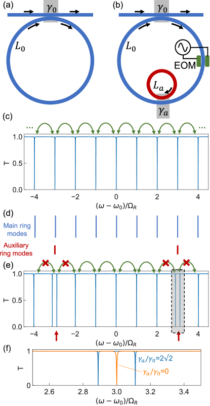
To truncate such a lattice and create boundaries, we couple an auxiliary ring resonator of a smaller length , corresponding to a larger FSR [Fig. 1(b)]. Here we have assumed that the auxiliary ring is made of a waveguide with the same group velocity as the main ring, and is coupled to the main ring via a directional coupler with an amplitude coupling coefficient . Note that similar geometries have previously been used for optical communications, reconfigurable frequency conversion and demonstrating coupled-resonator induced transparency [38, 39, 40, 41, 42, 43].
As an illustration, Fig. 1(d) shows the spectral positions of the main cavity and auxiliary ring modes for in the absence of modulation. The corresponding transmission spectrum is plotted in Fig. 1(e). Near the frequencies where the resonances from the two rings align, if , a splitting is induced [Fig. 1(f)]. Here is the power splitting ratio of the directional coupler between the input-output waveguide and the main ring. Unlike the spectrum in Fig. 1(c), the spectrum here in Fig. 1(e) is no longer periodic with respect to translation by along the frequency axis.
When the modulation is again introduced in the main ring with a modulation frequency , the modulation can induce the transition between some of the modes. Specifically in Fig. 1(e), the green arrows represent the allowed modulation-induced couplings along the frequency dimension, whereas the red crosses represent inhibition of the coupling to modes that are perturbed by the auxiliary ring. A series of several finite lattices are formed, which are separated by the split resonances induced by the auxiliary ring. The presence of the auxillary ring thus can introduce a sharp boundary in the synthetic dimension.
Characterization of the unmodulated resonators
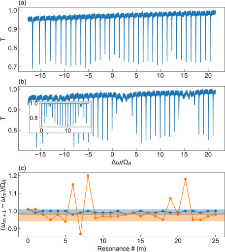
To experimentally characterize the resonator in the absence of modulation, we measure the transmission spectra [Fig. 2] in an experimental realization of the setup shown in Fig. 1(a). The details of the experiments, which are implemented using fiber rings, are provided in the Supplementary Information Section I. Without the auxiliary ring, the transmission features a set of resonant dips, with minimum transmission that are similar for all the dips. These dips correspond to the resonances of the main ring. The frequency spacing of the nearest resonances as a function of the order of resonances is plotted as the blue line in Fig. 2(c). We see that the frequency spacing is nearly a constant. In the presence of coupling to the auxiliary ring, there is marked increase in near the main cavity modes that are aligned to the auxiliary ring modes [Fig. 2(b)]. The increase in is in accordance with scattering matrix simulations including loss in the auxiliary ring [inset of Fig. 2(b)], and this loss was ignored in Fig. 1(d),(e) for simplicity. Around the resonant frequencies of the auxiliary ring, we see that the resonances of the coupled system are no longer equally spaced [orange line in Fig. 2(c)]. Additionally, for the coupled system, the frequency spacings between modes far away from the resonances of the auxiliary ring, which we define as the FSR of our coupled ring system, is smaller as compared to the FSR of the main ring by itself [Fig. 2(c), see Supplementary Section II for an analytical derivation of this effect].
Measurement of boundary effects in 1D lattice space
For the remainder of the paper, we will consider a modulated resonator. We first demonstrate the effect of a boundary created by the auxiliary ring by measuring the steady state intensity distribution in the synthetic frequency dimension [Fig. 3] in the presence of modulation. We excite the system at a frequency near one of the resonances of the main ring, the order of which is denoted by . is gradually swept, and the detuning forms the vertical axis in Figs. 3(a), (b), (d)-(f). At each input frequency, the frequency-lattice distribution of the steady-state cavity field is obtained from a heterodyne measurement of the transmitted field [44]. This frequency sideband number is denoted by along the horizontal axis in Fig. 3.
In the absence of the auxiliary ring, the transmitted field contains a large number of sidebands [Fig. 3(a)]. This experimental data matches well with the simulated spectrum in Fig. 3(b) which was calculated using a Floquet scattering matrix analysis. The steady state field intensity of the -th sideband away from the input falls off exponentially as [see Fig. 3(c) bottom], for large [11], where and are the ring photon lifetime and the modulation strength respectively.
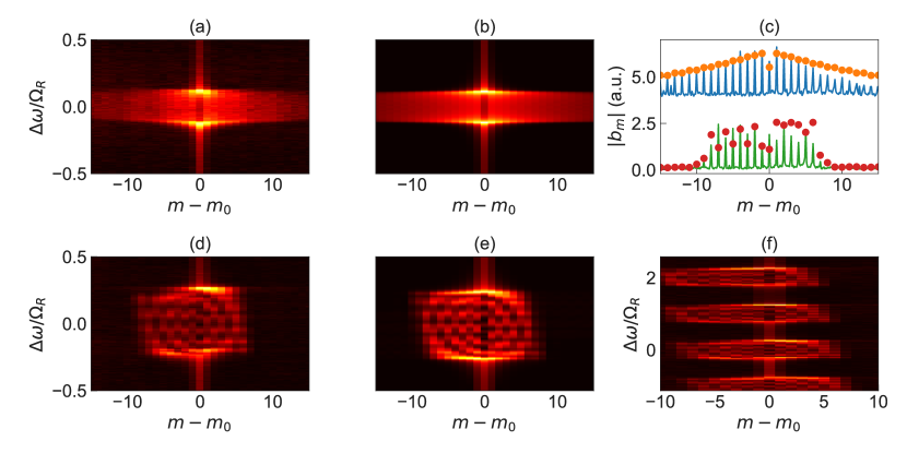
On the other hand, when the auxiliary ring is coupled to the main ring, the output field contains a far smaller number of sidebands. This indicates that within the ring, the only modes excited are those that lie between the two boundaries along the frequency axis [experiment: Fig. 3(d), simulations: Fig. 3(e)]. We also observe interference fringes created by reflections from the boundaries. Note that the strengths of the fringes increase with an increase in the modulation-induced coupling strength, since light is able to traverse along the frequency axis for longer distance before getting dissipated. However, the strong confinement of light to within the boundaries is preserved as long as the splitting induced by the auxiliary ring resonator is larger than . Figure 3(f) illustrates the spectra upon exciting various lattice sites within the two boundaries. This result was obtained by sweeping the input laser detuning over a large range . Since the measured heterodyne spectrum is always referenced to the input laser frequency mode , we observe a shift of the output spectrum towards lower frequency sidebands as increases.
Measurement of 1D boundary effects in reciprocal space
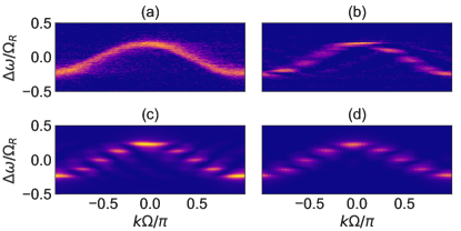
An infinite lattice that obeys discrete translational symmetry can be characterized by a conserved continuous quantum number, the Bloch quasimomentum , which labels the bulk properties in reciprocal space. For each , one or more continuous bands are formed which correspond to the eigenenergy spectrum of the infinite lattice. In the frequency synthetic dimension, the wavevector along the frequency axis corresponds to a time variable. We have previously demonstrated a synthetic-space band structure spectroscopy technique [9]. In this technique, we scan the input frequency of a continuous-wave laser. For each frequency, after the transient dissipates, we measure the transmission intensity as a function of time. Since the time corresponds to the wavevector along the synthetic frequency dimension, the resulting two-dimensional plot of transmission as a function of frequency and wavevector then provides a measure of the bandstructure. An example of such a measurement, for our system in the absence of the auxiliary ring, is shown in Fig. 4(a). The locations of the peaks in the frequency-wavevector space closely match the band structure of a one-dimensional tight-binding model with nearest neighbor coupling.
We repeat the same measurement in the presence of the auxiliary ring [Fig. 4(b)]. We see strong excitation of the system only at a discrete set of frequencies, as expected since the presence of the two boundaries results in a discrete set of eigenstates. For each of these eigenstates, the wavevector components spread over a range, centered at approximately where the wavevector would be at the same frequency for the infinite system. The experimental results in Figs. 4(b) agree excellently with numerical simulation results shown in Fig. 4(c) based on a Floquet scattering matrix analysis of the coupled ring system. Moreover, the numerical results indicate that the discrete eigenfrequencies that we observe in Fig. 4(b) agree with tight-binding simulations [Fig. 4(d)] where open boundaries are imposed on the two ends of a finite lattice, providing further evidence of a sharp boundary that we create.
Demonstration of boundary effects in a quantum Hall ladder
We now demonstrate the effect of boundary on a topologically nontrivial system, the two-leg quantum Hall ladder [45], and show how it enables us to observe topologically robust transport of light along the frequency axis for the first time. To construct a two-leg quantum Hall ladder, we use a setup schematically shown in Fig. 5(a), where we couple a pair of main ring resonators. The main ring on the left is in addition coupled to an auxiliary ring. We ensure that the FSR of the main ring on the right matches the FSR of the coupled system consisting of the main ring on the left together with the auxiliary ring. We modulate both of the main rings at a frequency MHz, which matches the FSR, with a relative phase difference in the modulations on the two rings [4]. The resulting Hamiltonian then describes a two-leg quantum Hall ladder [45, 16, 6] [Fig. 5(b)]:
| (2) |
where and represent the number of frequency modes in the left and right legs of the ladder respectively, and due to the presence of the auxiliary ring that couples to the main ring on the left. is the modulation induced hopping along the synthetic frequency dimension. represents the coupling between the two legs of the ladder, determined by the splitting ratio of the directional coupler that couples the two main rings together.
The model in Eq. (2) exhibits a uniform effective magnetic flux permeating each square plaquette of the lattice. For , time-reversal symmetry is broken; such a model then supports one-way chiral states on each leg which are immune to backreflections from the boundary or corner [Fig. 5(g),(h)]. This one-way nature derives from a parent 2D quantum Hall insulator which manifests strong topological protection [45, 46]. Thus, the setup allows us to study the interaction of boundaries with the topologically protected one-way chiral modes in a quantum Hall ladder.
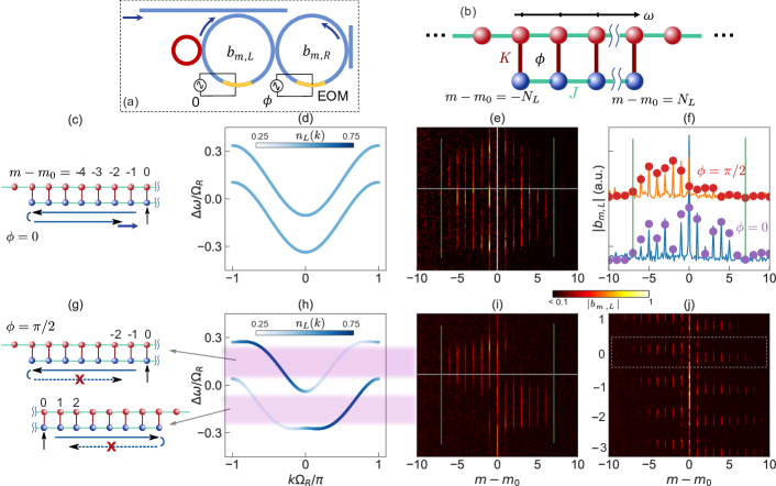
To demonstrate the effect of the boundary as induced by the auxiliary ring, we excite the left main ring in the setup as shown in Fig. 5(a). We choose the excitation frequency to match one of the lattice sites away from the boundary [Fig. 5(c) and (g)]. In the case of , the band structure for an infinite two-leg system is shown in Fig. 5(d). Since the system has time-reversal symmetry, the eigenstates equally occupy the left and the right legs and the system does not exhibit any chiral behavior. Consequently, with the excitation as shown in Fig. 5(c), we expect that the generated field will propagate to both sides of the excitation site. Also, we expect to see interference fringes between the site of excitation and the boundaries. In Fig. 5(e), we show the experimental results for this case where we measure the spectrum of the transmitted light via heterodyne detection (see Supplementary Information Section I). We indeed observe that the output field contains strong components on both sides of the excitation site . In Fig. 5(f), we plot the amplitude at various lattice sites for . We observe interference fringes due to the presence of the boundaries (indicated by green vertical lines), as exemplified by the dips at .
In the case of , the band structure for the infinite system is shown in Fig. 5(h). Since the system breaks time-reversal symmetry, the eigenstates show asymmetry in occupation between the left leg and the right leg, as illustrated in Fig. 5(h) where the color gradient shows the projection of the eigenstate on the left leg. Hence, with the excitation shown in Fig. 5(g) where the left leg is excited, we expect that the generated field will propagate to higher frequencies for the lower band, and to lower frequencies for the upper band, as determined by the sign of the group velocities of the chiral modes in Fig. 5(h). Also, we do not expect to see interference fringes between the site of excitation and the boundaries, since the one-way nature of the chiral modes should suppress back-reflection from the boundaries [schematics in Fig. 5(g)]. In Fig. 5(i), we show the experimental results for this case where we measure the spectrum of the transmitted light via heterodyne detection. Strikingly different from Fig. 5(e), we indeed observe that the output field contains frequency components almost exclusively for modes to the left of the excitation () for the upper band, in the one-way detuning range shaded in pink in Fig. 5(h). The direction of frequency conversion switches for the lower band. In Fig. 5(f), we plot the experimentally measured amplitude at various lattice sites as the orange curve, which agrees well with Floquet scattering matrix simulations (red dots). The one-way nature as well as the absence of interference fringes are borne out in this amplitude distribution in frequency lattice space. Fig. 5(j) plots the amplitude distribution for a wide range of detuning , corresponding to the excitation of different lattice sites along the frequency dimension. We observe that the topological robustness of light transport, as evidenced by the one-way nature and the lack of fringes, persists as we excite modes with different distances from the boundary.
Discussion
We have demonstrated the construction of sharp boundaries in synthetic dimensions by coupling an auxiliary ring resonator to a dynamically modulated ring, using a platform based on optical fibers. Recent progress in nanophotonic electro-optic modulators [47, 48] incorporated into low-loss microring resonators provide opportunities for scalable on-chip integration of such concepts. This approach can be generalized to higher dimensions for exploring nontrivial topological boundary phenomena [49, 11, 50], both in conventional topological insulators as well as in higher-order topological insulators. Recent demonstrations on using perturbations to the cross section of the ring [51, 52] promise further flexibility in creating such boundaries. Our results also show that the energy of a synthetic lattice can be confined to a finite number of sites by coupling to additional auxiliary resonators, which is critical in efficient implementations of linear transformations or matrix-vector multiplications [28]. Our work should significantly advance the capabilities of synthetic dimensions in both topological photonics and for optical signal processing.
References
References
- Boada et al. [2012] O. Boada, A. Celi, J. I. Latorre, and M. Lewenstein, Quantum Simulation of an Extra Dimension, Phys. Rev. Lett. 108, 133001 (2012).
- Yuan et al. [2018a] L. Yuan, Q. Lin, M. Xiao, and S. Fan, Synthetic dimension in photonics, Optica 5, 1396 (2018a).
- Ozawa and Price [2019] T. Ozawa and H. M. Price, Topological quantum matter in synthetic dimensions, Nature Reviews Physics 1, 349 (2019).
- Yuan et al. [2016] L. Yuan, Y. Shi, and S. Fan, Photonic gauge potential in a system with a synthetic frequency dimension, Opt. Lett. 41, 741 (2016).
- Ozawa et al. [2016] T. Ozawa, H. M. Price, N. Goldman, O. Zilberberg, and I. Carusotto, Synthetic dimensions in integrated photonics: From optical isolation to four-dimensional quantum Hall physics, Phys. Rev. A 93, 043827 (2016).
- Dutt et al. [2020a] A. Dutt, Q. Lin, L. Yuan, M. Minkov, M. Xiao, and S. Fan, A single photonic cavity with two independent physical synthetic dimensions, Science 367, 59 (2020a).
- Wang et al. [2021] K. Wang, A. Dutt, K. Y. Yang, C. C. Wojcik, J. Vučković, and S. Fan, Generating arbitrary topological windings of a non-Hermitian band, Science 371, 1240 (2021).
- Bell et al. [2017] B. A. Bell, K. Wang, A. S. Solntsev, D. N. Neshev, A. A. Sukhorukov, and B. J. Eggleton, Spectral photonic lattices with complex long-range coupling, Optica 4, 1433 (2017).
- Dutt et al. [2019a] A. Dutt, M. Minkov, Q. Lin, L. Yuan, D. A. B. Miller, and S. Fan, Experimental band structure spectroscopy along a synthetic dimension, Nature Communications 10, 3122 (2019a).
- Qin et al. [2018] C. Qin, F. Zhou, Y. Peng, D. Sounas, X. Zhu, B. Wang, J. Dong, X. Zhang, A. Alù, and P. Lu, Spectrum Control through Discrete Frequency Diffraction in the Presence of Photonic Gauge Potentials, Phys. Rev. Lett. 120, 133901 (2018).
- Hu et al. [2020a] Y. Hu, C. Reimer, A. Shams-Ansari, M. Zhang, and M. Loncar, Realization of high-dimensional frequency crystals in electro-optic microcombs, Optica 7, 1189 (2020a).
- Wang et al. [2020] K. Wang, B. A. Bell, A. S. Solntsev, D. N. Neshev, B. J. Eggleton, and A. A. Sukhorukov, Multidimensional synthetic chiral-tube lattices via nonlinear frequency conversion, Light: Science & Applications 9, 132 (2020).
- Thouless et al. [1982] D. J. Thouless, M. Kohmoto, M. P. Nightingale, and M. den Nijs, Quantized Hall Conductance in a Two-Dimensional Periodic Potential, Phys. Rev. Lett. 49, 405 (1982).
- Benalcazar et al. [2017] W. A. Benalcazar, B. A. Bernevig, and T. L. Hughes, Quantized electric multipole insulators, Science 357, 61 (2017).
- Ghatak et al. [2019] A. Ghatak, M. Brandenbourger, J. van Wezel, and C. Coulais, Observation of non-Hermitian topology and its bulk-edge correspondence, arXiv:1907.11619 (2019).
- Mancini et al. [2015] M. Mancini, G. Pagano, G. Cappellini, L. Livi, M. Rider, J. Catani, C. Sias, P. Zoller, M. Inguscio, M. Dalmonte, and L. Fallani, Observation of chiral edge states with neutral fermions in synthetic Hall ribbons, Science 349, 1510 (2015).
- Luo et al. [2015] X.-W. Luo, X. Zhou, C.-F. Li, J.-S. Xu, G.-C. Guo, and Z.-W. Zhou, Quantum simulation of 2D topological physics in a 1D array of optical cavities, Nature Communications 6, 7704 (2015).
- Regensburger et al. [2012] A. Regensburger, C. Bersch, M.-A. Miri, G. Onishchukov, D. N. Christodoulides, and U. Peschel, Parity–time synthetic photonic lattices, Nature 488, 167 (2012).
- Chalabi et al. [2019] H. Chalabi, S. Barik, S. Mittal, T. E. Murphy, M. Hafezi, and E. Waks, Synthetic Gauge Field for Two-Dimensional Time-Multiplexed Quantum Random Walks, Phys. Rev. Lett. 123, 150503 (2019).
- Leefmans et al. [2022] C. Leefmans, A. Dutt, J. Williams, L. Yuan, M. Parto, F. Nori, S. Fan, and A. Marandi, Topological dissipation in a time-multiplexed photonic resonator network, Nat. Phys. 10.1038/s41567-021-01492-w (2022).
- Lustig et al. [2019] E. Lustig, S. Weimann, Y. Plotnik, Y. Lumer, M. A. Bandres, A. Szameit, and M. Segev, Photonic topological insulator in synthetic dimensions, Nature 567, 356 (2019).
- Su et al. [1979] W. P. Su, J. R. Schrieffer, and A. J. Heeger, Solitons in Polyacetylene, Phys. Rev. Lett. 42, 1698 (1979).
- Dutt et al. [2020b] A. Dutt, M. Minkov, I. A. D. Williamson, and S. Fan, Higher-order topological insulators in synthetic dimensions, Light: Science & Applications 9, 131 (2020b).
- Mittal et al. [2019] S. Mittal, V. V. Orre, G. Zhu, M. A. Gorlach, A. Poddubny, and M. Hafezi, Photonic quadrupole topological phases, Nature Photonics 13, 692 (2019).
- Okuma et al. [2020] N. Okuma, K. Kawabata, K. Shiozaki, and M. Sato, Topological Origin of Non-Hermitian Skin Effects, Phys. Rev. Lett. 124, 086801 (2020).
- Weidemann et al. [2020] S. Weidemann, M. Kremer, T. Helbig, T. Hofmann, A. Stegmaier, M. Greiter, R. Thomale, and A. Szameit, Topological funneling of light, Science 368, 311 (2020).
- Bergholtz et al. [2021] E. J. Bergholtz, J. C. Budich, and F. K. Kunst, Exceptional topology of non-Hermitian systems, Rev. Mod. Phys. 93, 015005 (2021).
- Buddhiraju et al. [2021] S. Buddhiraju, A. Dutt, M. Minkov, I. A. D. Williamson, and S. Fan, Arbitrary linear transformations for photons in the frequency synthetic dimension, Nature Communications 12, 2401 (2021).
- Chen et al. [2021] H. Chen, N. Yang, C. Qin, W. Li, B. Wang, T. Han, C. Zhang, W. Liu, K. Wang, H. Long, X. Zhang, and P. Lu, Real-time observation of frequency Bloch oscillations with fibre loop modulation, Light: Science & Applications 10, 48 (2021).
- Lee et al. [2020] N. R. A. Lee, M. Pechal, E. A. Wollack, P. Arrangoiz-Arriola, Z. Wang, and A. H. Safavi-Naeni, Propagation of microwave photons along a synthetic dimension, Phys. Rev. A 101, 053807 (2020).
- Bersch et al. [2009] C. Bersch, G. Onishchukov, and U. Peschel, Experimental observation of spectral Bloch oscillations, Optics letters 34, 2372 (2009).
- Li et al. [2021] G. Li, Y. Zheng, A. Dutt, D. Yu, Q. Shan, S. Liu, L. Yuan, S. Fan, and X. Chen, Dynamic band structure measurement in the synthetic space, Science Advances 7, eabe4335 (2021).
- Balčytis et al. [2021] A. Balčytis, T. Ozawa, Y. Ota, S. Iwamoto, J. Maeda, and T. Baba, Synthetic dimension band structures on a Si CMOS photonic platform, arXiv:2105.13742 (2021).
- Wang et al. [2021b] K. Wang, A. Dutt, C. C. Wojcik, and S. Fan, Topological complex-energy braiding of non-Hermitian bands, Nature 598, 59 (2021b).
- Shan et al. [2020] Q. Shan, D. Yu, G. Li, L. Yuan, and a. X. Chen, One-Way Topological States Along Vague Boundaries in Synthetic Frequency Dimensions Including Group Velocity Dispersion (Invited), Progress In Electromagnetics Research 169, 33 (2020).
- Baum and Refael [2018] Y. Baum and G. Refael, Setting Boundaries with Memory: Generation of Topological Boundary States in Floquet-Induced Synthetic Crystals, Phys. Rev. Lett. 120, 106402 (2018).
- Yuan et al. [2021] L. Yuan, A. Dutt, and S. Fan, Synthetic frequency dimensions in dynamically modulated ring resonators, APL Photonics 6, 071102 (2021).
- Haldar et al. [2013] R. Haldar, S. Das, and S. K. Varshney, Theory and Design of Off-Axis Microring Resonators for High-Density On-Chip Photonic Applications, J. Lightwave Technol. 31, 3976 (2013).
- Souza et al. [2014] M. C. M. M. Souza, L. A. M. Barea, F. Vallini, G. F. M. Rezende, G. S. Wiederhecker, and N. C. Frateschi, Embedded coupled microrings with high-finesse and close-spaced resonances for optical signal processing, Opt. Express 22, 10430 (2014).
- Wang et al. [2010] J. Wang, Y. Zhang, J. Zhang, Y. Cai, X. Zhang, and P. Yuan, Simultaneous observation of superluminal and slow light propagation in a nested fiber ring resonator, Opt. Express 18, 13180 (2010).
- Haldar et al. [2014] R. Haldar, A. D. Banik, and S. K. Varshney, Design of CMOS compatible and compact, thermally-compensated electro-optic modulator based on off-axis microring resonator for dense wavelength division multiplexing applications, Opt. Express 22, 22411 (2014).
- Hu et al. [2021] Y. Hu, M. Yu, D. Zhu, N. Sinclair, A. Shams-Ansari, L. Shao, J. Holzgrafe, E. Puma, M. Zhang, and M. Lončar, On-chip electro-optic frequency shifters and beam splitters, Nature 599, 587 (2021), .
- Smith et al. [2004] D. D. Smith, H. Chang, K. A. Fuller, A. T. Rosenberger, and R. W. Boyd, Coupled-resonator-induced transparency, Phys. Rev. A 69, 063804 (2004).
- Dutt et al. [2019b] A. Dutt, M. Minkov, Q. Lin, L. Yuan, D. A. B. Miller, and S. Fan, Experimental Demonstration of Dynamical Input Isolation in Nonadiabatically Modulated Photonic Cavities, ACS Photonics 6, 162 (2019b).
- Hügel and Paredes [2014] D. Hügel and B. Paredes, Chiral ladders and the edges of quantum Hall insulators, Physical Review A 89, 023619 (2014).
- Wang et al. [2008] Z. Wang, Y. D. Chong, J. D. Joannopoulos, and M. Soljačić, Reflection-Free One-Way Edge Modes in a Gyromagnetic Photonic Crystal, Physical Review Letters 100, 013905 (2008).
- Zhang et al. [2019] M. Zhang, B. Buscaino, C. Wang, A. Shams-Ansari, C. Reimer, R. Zhu, J. M. Kahn, and M. Lončar, Broadband electro-optic frequency comb generation in a lithium niobate microring resonator, Nature 568, 373 (2019).
- Tzuang et al. [2014] L. D. Tzuang, M. Soltani, Y. H. D. Lee, and M. Lipson, High RF carrier frequency modulation in silicon resonators by coupling adjacent free-spectral-range modes, Optics Letters 39, 1799 (2014).
- Yuan et al. [2019] L. Yuan, Q. Lin, A. Zhang, M. Xiao, X. Chen, and S. Fan, Photonic Gauge Potential in One Cavity with Synthetic Frequency and Orbital Angular Momentum Dimensions, Physical Review Letters 122, 083903 (2019).
- Yuan et al. [2018b] L. Yuan, M. Xiao, Q. Lin, and S. Fan, Synthetic-space with arbitrary dimensions in a few rings undergoing dynamic modulation, Physical Review B 97, 104105 (2018b).
- Lu et al. [2020] X. Lu, A. Rao, G. Moille, D. A. Westly, and K. Srinivasan, Universal frequency engineering tool for microcavity nonlinear optics: multiple selective mode splitting of whispering-gallery resonances, Photon. Res., PRJ 8, 1676 (2020).
- Lu et al. [2022] X. Lu, A. McClung, and K. Srinivasan, High-Q slow light and its localization in a photonic crystal microring, Nat. Photon. 16, 66 (2022).
Acknowledgements
We acknowledge David A. B. Miller for providing lab space and equipment, and Meir Orenstein and Momchil Minkov for useful discussions. This work is supported by a Vannevar Bush Faculty Fellowship from the U. S. Department of Defense (Grant No. N00014-17-1-3030) and a MURI project from the U.S. Air Force Office of Scientific Research (grant no. FA9550-18-1-0379). L.Y. also acknowledges the support by National Natural Science Foundation of China (11974245, 12122407).
Competing interests
The authors declare no competing interests.