The EL-X8 computer and the BOL detector
Networking, programming, time-sharing and data-handling
in the Amsterdam nuclear research project ‘BOL’
A personal historical review
Abstract
From 1967 to 1974, an Electrologica X8 computer was installed at the Institute for Nuclear Research (IKO) in Amsterdam, primarily for online and offline evaluation of experimental data, an application quite different from its ‘brother’s’, X8’s. During that time, the nuclear detection system ‘BOL’111‘BOL’ is Dutch for ‘SPHERE’. was in operation to study nuclear reactions. The BOL detector embodied a new and bold concept. It consisted of a large number of state-of-the-art detection units, mounted in a spherical arrangement around a target in a beam of nuclear particles. Two minicomputers performed data acquisition and control of the experiment and supported online visual display of acquired data. The X8 computer, networked with the minicomputers, allowed fast high-level data processing and analysis. Pioneering work in both experimental nuclear physics as well as in programming, turned out to be a surprisingly good combination. For the network with the X8 and the minicomputers, advanced software layers were developed to efficiently and flexibly program extensive data handling.
To appear in G. Alberts and J.F. Groote (Eds), Tales of Electrologica.
London: Springer Nature, 2022, pp 123-152
Keywords History of Computing Computing Infrastructure and Software History of Experimental Nuclear Physics Data Analysis
1 Introduction and background
The establishment of the Mathematical Center (MC)222The Mathematical Center (MC) was founded in 1946 and housed in a school building in East Amsterdam. The first director was Johannes van der Corput. The MC installed a Computation Department in 1947, led by Adriaan van Wijngaarden. In 1983 the name was changed to Center for Mathematics and Informatics (CWI). and of the Institute for Nuclear Research (IKO)333IKO was established in 1946 in buildings of a former gas factory in East Amsterdam. The founding partners were Philips, the Foundation for Fundamental research on Matter (FOM) and the City of Amsterdam. The first director was Cornelis J. Bakker, who later became director of CERN, the institute currently known as European Center of Particle Physics (Cern) in Geneva. In 1975, IKO became part of NIKHEF, the National Institute for Nuclear- and High-Energy Physics – later renamed the National Institute for Subatomic Physics (Nikhef). was firmly rooted in the post-World War II revival of science in Europe. One of the many important ramifications was the groundbreaking development of computers at the MC, in conjunction with a large-scale nuclear detection system at IKO. As described in this article, direct and indirect links between these two successful institutes proved to be extremely fruitful, in particular for IKO.
It was in the summer of 1953, when I was 16 years old, that I had the opportunity to spend six weeks in the computing department of the MC, where I was able to ‘assist’ in assembling and testing circuits for the second version of the ARRA computer444This ‘job’ was arranged for me by prof. David van Dantzig, mathematician, statistician, MC department head, one of the founders of the MC, and my father, who paid me the equivalent salary of a simple holiday job at an enterprise (my original intention), because he thought that staying at the MC would be better for my future. He was right.. There, I met prof. Adriaan van Wijngaarden, Bram Loopstra, Carel Scholten, Edsger Dijkstra, and Jaap Zonneveld, the team responsible for a decade of inventive computer developments555At the MC the first Dutch computers were developed: i.e. vacuum tube machines ARRA-I (1952), ARRA-II (1954) and FERTA (1955); later the partly transistorized ARMAC (1956) and the fully transistorized X1. at the MC, the early pioneers of Dutch information and computer technology in hardware as well as in software. Their work was continued at the first Dutch computer manufacturer, Electrologica666Electrologica was founded in 1956 by A. van Wijngaarden, B.J. Loopstra and C.S. Scholten from the MC, and J. Engelfriet, from the assurance company Nillmij. Electrologica developed and produced the X1 (1959) and finally the ‘eightfold’ faster X8 (1965). In 1968 Electrologica was taken over by Philips and renamed ‘Philips-Electrologica’..
The initial series of Electrologica computers was the ‘EL-X1’, the first of which was installed at the MC in 1960. The MC offered courses on coding the X1 machine. These courses were open to people from outside the MC, and I, at the time a physics student at IKO, attended these, receiving a coding certificate in 1961. On top of that, Van Wijngaarden’s inspiring classes in numerical mathematics at the university of Amsterdam made me and others at IKO familiar with programming techniques in the Algol-60 language. This turned out to be quite relevant for IKO, since in the early 1960s the need for data reduction, analysis, and theoretical modeling increased significantly. For me, ist meant that my use of the very noisy mechanical Monroe and Friden motor driven calculators was steadily replaced by silent programming. The MC had created an open-shop service for the EL-X1 computer, which allowed us physicists and technicians to write our programs during daytime and run these ourselves at the MC during evenings and nights. We spent nights running programs on the X1 with a portable radio on the memory cabinet: the beeping and crackling of the radio interference kept telling us how far the data processing had progressed.
Our institute, IKO, had been set up to house a synchro-cyclotron777In principle, a circular accelerator can reach much higher energies for charged particles than a linear accelerator. In a synchro-cyclotron, the high frequency/high voltage acceleration mechanism is adapted to the relativistic mass increase of particles with increasing energy; Heyn, F.A., and J.J. Burgerjon (1952) Het synchro-cyclotron te Amsterdam. Philips Technisch Tijdschrift 14:291-307; Luijckx, Guy (1980) Het cyclotron. Philips Technisch Tijdschrift 39(10):274-276., the first circular accelerator of nuclear particles in Europe and at that time the second largest in the world. The cyclotron, based on principles developed in the US, had been constructed by the Philips company. It became operational in 1949, enabling irradiations inside the cyclotron. Accelerated particles of various types888Originally only deuterons and alpha-particles (4He-nuclei) could be accelerated, later also protons and 3He-nuclei. with various energies could hit a target inserted at the edge of the cyclotron. Nuclear collisions produced radioactive nuclei inside the target, which was removed after irradiation999In 1966, the 15,000 internal irradiation took place. for radiochemical and nuclear spectroscopy studies, as well as for medical purposes.
Not long before I started as a student at IKO in 1959 the cyclotron had been equipped with an external beam system to guide nuclear particles to a target far outside the cyclotron, where they collided with the target nuclei. Generally, nuclear particles can fly away from such collisions in ‘any’ direction. When caught in special detectors near the target in a vacuum scattering chamber, detected particles can reveal aspects of the collision process, of the nuclear reactions that occur and of the structure of the nuclei involved.
The IKO ‘nuclear reaction group’, also called ‘deflection group’, in which I participated for the experimental part of my study, had been responsible for the extraction and deflection of the beam from the cyclotron and its use for nuclear reaction experiments. In addition to the internal irradiations, the external beam with various instrumental setups made it possible to perform a range of nuclear experiments, including the one for my own master’s thesis in 1962.
In the first few years of the 1960s, a second accelerator was built at IKO, the linear electron accelerator ‘EVA’. All the activities relating to both accelerators were part of a broad and fruitful research program that was a rich source for publications in international journals over the years. In this article, we will concentrate on parts of the work with the cyclotron.
2 The BOL project
In 1964, I returned to the nuclear reactions group after a one-year stay abroad101010At the Weizmann Institute of Science, Rehovot, Israel, I studied nuclear theory and made an analysis of my master’s thesis measurements. This was made possible by a stipend from the Dutch organization for scientific research (ZWO).. By that time, measurements at IKO as well as in laboratories elsewhere had shown the importance of detecting two or more particles emerging simultaneously from the same nuclear collision, called ‘coincidences’. These provided much more detailed information on the ongoing nuclear reactions and on the structure of the colliding nuclei compared to the more common ‘singles’ measurements. This was particularly true for ‘few body reactions’, which could be well described theoretically and give information about nuclear dynamics and forces.
After various feasibility studies, initiated by our group leader, Leo A.Ch. Koerts, a broad instrumental development was set up to construct a brand new type of detection system to measure coincidences.111111Koerts, L.A.Ch., K. Mulder, J.E.J. Oberski and R. van Dantzig (1971) The BOL nuclear research project. Nucl. Instr. Meth. 92:157-160. The system would include a then revolutionarily shaped, spherical scattering chamber around the target, containing many detection units, the whole resembling an inverted insect’s eye. This became the BOL project.121212Dantzig, René van (2017) Project BOL (1964–1977), Historical overview. https://www.nikhef.nl/history/bol-EN.
One underlying idea was that the number of pairs of detection units rises almost quadratically with the number of detection units. Therefore, also the probability to catch coincident particles would rise quadratically with that number. Another principal idea was that the detection units, when placed in a spherical arrangement, could sample nearly the entire measurement space at the same time.
An ambitious team of enthusiastic physicists and technicians, the BOL team, was formed around Koerts, the founding father and overall coordinator of the BOL project. Three very motivated physicists in their twenties, Karel Mulder, Jona E.J. Oberski, and myself, coordinated the developments of, respectively, mechanical and detection hardware, electronics and computing hardware, and software. However, all three of us were more or less involved in all BOL activities. This meant that we had a broad spectrum of unofficial duties and responsibilities, although none of us had a PhD yet. These were different times from today! We had a semi-permanent employment contract at IKO and were not supposed to write our PhD theses until we had obtained our own significant physics results, whatever time it would take. Building the equipment to obtain these required many years’ work, including substantial delays! Gradually, the team was expanded with younger PhD students, master’s students and technicians. Most of them made vital contributions to our project. From the beginning, we operated in a remarkably free environment, based on mutual trust and equality, without any authoritarian hierarchy or bureaucracy.
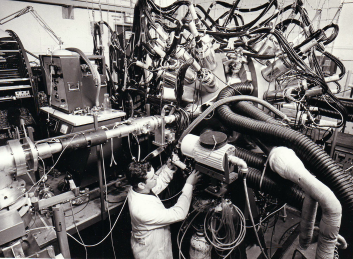
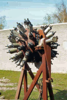
The BOL detector was mainly designed and constructed during the years 1964-1966. The apparatus came into operation with a steadily growing number of rocket-shaped detection units, ultimately 64 in all. When mounted, each had its silicon semiconductor ‘detector telescope’ in a vacuum scattering chamber, cooled at minus C and pointing at the target; the external part contained air-cooled front-end electronics (Fig. 1).
BOL was the first ‘4-type’131313‘4-type’ means sampling all 4 steradians, the total maximum solid angle (the surface of a unit sphere) by an internally directed omnidirectional looking fine-meshed ‘fly’s eye’. The coverage for detection was typically 10% for single particles and 1% for coincidences, values experimentally unprecedented at that time. nuclear physics multi-detector system in the world that simultaneously covered largely all scattering angles and could determine the ‘type’ of the detected particles. It was equipped with state-of-the-art detectors developed in close collaboration with the BOL team by the Philips NatLab Nuclear Detection group.141414Dantzig, René van (1980) BOL. Philips Technisch Tijdschrift. 39/10:286-291 (Dutch, English and French edition). The Philips NatLab Nuclear Detection group led by dr. Wim Hofker included Piet Bakker, Jarich Politiek, Dick Oosthoek, and others. It was housed at the IKO campus. An essential innovation was the Checkerboard detector, which made it possible to determine a particle impact position with millimeter precision, corresponding to typically 1 degree in scattering angle. This detector turned out to be a first step in the development of detectors currently essential in high energy particle physics experimentation.151515Heijne, Erik H.M. (2003) Semiconductor detectors in the low countries. Nucl. Instr. Meth. Phys. A 309:1-16.
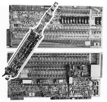
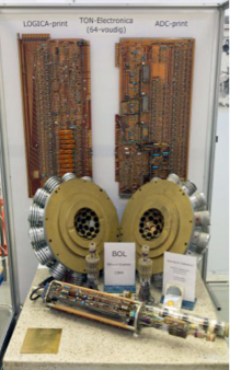
In line with the complexity and the new detection methods, the technical realization of BOL implied new approaches and specialized expertise161616The electronics were designed and developed with indispensable ingenuity and perseverance by Rein F. Rumphorst, head of the electronics group, assisted by Johan Dieperink, Erwin Kok and others. on the design, testing, and production of a massive and at the same time delicate electronic system.171717Oberski, Jona E.J., et al. (1971a) Electronics of the BOL System. Nucl. Instr. Meth. 92:177-187. Each of the 64 detection channels consisted of electronics for a) preprocessing the signals inside the detection units, as well as two large printed circuit boards with b) system logic and c) digitization using several analog-to-digital converters (ADCs). One of these – as a masterpiece – was a 4096-channel high-precision highly linear ADC operating at 100 MHz, a marvel far ahead of its time. The boards (Fig. 2) were radially mounted in adjacent cylindrical frames, the ‘double drum’. To illustrate that all the hard work was not without humor, each ADC-board carried a motto, which freely translated to: ‘Computer at any speed, this ADC will floor it indeed’.
Compared to what was available commercially those days, the resulting BOL electronics were unrivaled in terms of precision, measurement speed, and size.181818In total, the BOL electronics contained about 40,000 transistors, 100,000 passive components, 35 m2 circuit board, and 13 km of cabling, all of which were huge quantities at that time for such equipment. Each of the 64 detector units had its own electronic channel with manual control of several voltage parameters (Fig. 3). All channels had at the-back end a 72-bit register. This held all digital data of one detected particle, a ‘single particle event’. The 72 bits were made-up of ‘bites’, each containing a measured value – for instance, an energy signal from the detection telescope (12 bits), a similar signal from the checkerboard detector (7 bits), a mark to indicate which single particle events belonged together to form a coincidence event, and others. The ‘event data’ were read out from the detection channels through a sequencer by a minicomputer (see Section 7), part of a dedicated computer network.
From 1965 onwards, the BOL detector and its infrastructure were gradually produced, assembled and commissioned. Creating BOL gave rise to a variety of technological challenges for IKO, and the project involved about half of the staff of the institute. Their joint effort: assembling a complex mechanical construction with subtle cooling and vacuum hardware, fragile detectors, and the intricate electronics system. For everyone involved, these years offered a wealth of experience. A lot of details had to be thought through in advance, while it was not yet clear how matters would turn out.
In 1968, we obtained the first results with successively 10, 20 and 30 detection units. From that time on, the system was systematically expanded, debugged and increasingly used for experiments with day and night data recording periods and subsequent analysis. This continued until the summer of 1973, when BOL was put on stand-by.
Innovative as they were, BOL and the cyclotron had their limitations. In order to avoid overload by accidental coincidences, the BOL experiment could handle only a low-intensity beam, matching the limited properties of the nearly two decades-old cyclotron, which was by itself no longer competitive with the modern cyclotrons that appeared elsewhere in Europe. For a decade BOL contributed significantly to the useful life of the ‘aged’ IKO-cyclotron, which was switched off in 1975.
3 Why and how the X8 came to IKO
At the beginning of my work at IKO in 1960, before the BOL-project, nuclear measurements were visualized online as 1-dimensional (1D) or 2-dimensional (2D) distributions of the number of detection signals (pulses) as a function of their height, ‘pulse height spectra’191919The pulses were sorted according to their height in bins and counted per bin.. These distributions were obtained with a ‘kicksorter’ or ‘pulse-height analyzer’, which contained one or two ADCs coupled to core-memory. In tandem with the recording process, a cycling process went along all memory addresses and displayed the spectrum dynamically on a CRT (cathode ray tube) display. Thus, we could visually follow during the experiment various spectra, corresponding to detection signals. Whenever a typical spectrum reached sufficient significance, we stopped the accumulation, studied the spectrum in detail and decided if it was what we wanted. If not, the experiment was readjusted and the procedure was repeated. The spectra could be printed, punched or saved on magnetic tape.
In general, a physics measurement with many adjustable elements in the system needs continuous monitoring and supervision of the system behavior. In addition, at the start-up of the measurement and at any time when changes are to be made, correct parameter adjustments or re-adjustments depend on adequate feedback concerning the system functions.
When we learned of small online computers in the US, it was immediately clear to us that replacing a kicksorter with a small general-purpose computer would be of tremendous advantage. The latter could do all of the data handling of the kicksorter much better, with much more flexibility and capacity!
When Digital Equipment Corporation (DEC)’s PDP-8 minicomputer202020This ‘Classic’ ‘Programmable Data Processor’, PDP-8, was the first real minicomputer (1965) having 4K 12-bit memory (32 pages of 128 words) and direct addressing within a page. The machine came with a Teletype ASR-33 serving as a console as well as paper tape punch and reader. Our machine also had a DF32 fixed head disk system with a storage capacity of 32k 12-bit words. In this article, we will refer to PDP-8 as ‘PDP8’. came on the market, we immediately purchased one for the data acquisition212121Dantzig, René van, et al. (1971a) Data acquisition with the BOL nuclear detection system. Nucl. Instr. Meth. 92:199-203. in the BOL project. We remember the wooden crate that came by plane from the US, from which a gleaming half-transparent PDP-8 computer emerged. All of us immediately fell in love with it! A second one, also for BOL, followed soon; several more were bought for other IKO research groups. From the beginning, perhaps because of our X1 coding experience, some of us were fascinated by programming these machines. The PDP8 4K Disk Monitoring System that came with them was primitive and not well-suited to our data acquisition needs. I initiated several developments, some of which are discussed in Section 1. Although both PDP8 machines offered us remarkable possibilities and were certainly essential for data acquisition and for experiment control, their capacity was far from sufficient for the needs we anticipated for online data handling for BOL.
From 1962, at all of IKO, the steadily growing computing requirements were annually evaluated and reported. A committee was appointed to prepare a plan on how to meet the future calculation needs. It was anticipated that the necessities for experiments at both IKO accelerators would be enough reason to seek funding for an in-house general-purpose computer. Up to that time, the offline calculations had practically all been done on the X1 at the MC. In 1964, it was foreseen that an online computer would ultimately be needed in 1966 to cover all IKO computing work.
In December 1962, Lout Jonkers, already acquainted with many aspects of computing, started his master’s study at IKO on our in-house computer issues. In 1964, after his first year of orientation and study, he wrote an internal report222222Jonkers, H.L., W.T.H. van Oers, H.R.E. Tjin A Djie (1964a) Discussie rond huidige en toekomstige behoefte aan rekencapaciteit van het IKO. IKO internal report Interiko 64. Archived at the National Museum Boerhaave, Leiden and at Nikhef, Amsterdam. concerning computer requirements for the various experimental setups in operation, in which he called for minicomputers as a solution to the experimental problems. At that moment, it was not yet clear at the laboratory level how fast new instrumentation (BOL) could change the requirements. In a slightly later report,232323Jonkers, H.L. (1964c) Computer requirements of the Institute for Nuclear Physics Research. IKO informal report. Archived at the National Museum Boerhaave, Leiden and at Nikhef, Amsterdam. he argued that: “for the sake of following the experiment and experimental control, the immediate interpretation of preliminary results requires complicated computations and data processing. Large quantities of information will have to be stored with high speed and in such a manner that later offline data reduction by a computer can be done economically.” This report also addressed the need for “multiprogramming with hardware program relocation and multi-level indirect addressing” and stated that “it is highly desirable that there will be close cooperation between the manufacturer and our laboratory.” We fully agreed with all of these points, and his discussions with us may have fleshed out the particulars.
The X8 in development at Electrologica had already been in the picture as a possible future IKO-machine since 1963. An ad hoc comparison242424Wapstra, A.H., H.L. Jonkers, and L.A.Ch. Koerts (1964) Internal note ‘Rekenmachine’. https://ub.fnwi.uva.nl/computermuseum/pdfs/Wapstra.pdf; Jonkers, H.L. (1964b) A comparison EL-X8 and CDC-3200 for on-line use. IKO internal report Interiko 64/5. Archived at the National Museum Boerhaave, Leiden and at Nikhef, Amsterdam. https://ub.fnwi.uva.nl/computermuseum/pdfs/X8vsCDC3200.pdf. between the X8 and the CDC 3200 from Control Data Corporation, a US company particularly active in Europe, showed advantages252525Although the X8 cycle time was longer, the instruction set was considered considerably more powerful. for the X8 – partly because of its appealing broader functionality and partly due to the possible support of Electrologica on hardware and software development. For comparison, offers were requested from several US computer manufactories, including CDC. It turned out that only the least expensive machine, the CDC 3200, was at all affordable. In 1964, the X8 – almost ready for rent or lease – became the anticipated (dreamed) machine for BOL as well as for other IKO applications, and consultations took place.
On the basis of the above evaluations, in 1964, IKO requested funding for the fiscal year 1965 from the overarching research agencies FOM (Foundation for Fundamental Research on Matter) and ZWO (the Dutch organization for pure scientific research) for the procurement of an electronic computer.262626Wapstra, A.H., H.L. Jonkers, et al. (1965) Voorstel tot aanschaffing van een electronische rekenautomaat ten behoeve van het fysisch werk op het Instituut voor Kernfysisch Onderzoek. Internal report IKO-2168. https://ub.fnwi.uva.nl/computermuseum/pdfs/X8aanschafvoorstel.pdf. Almost at the same time, the high-energy physics (HEF) community at the Zeeman Laboratory in Amsterdam requested funding along the same route for a computer, online and offline, for equipment measuring high-energy particle tracks on pictures taken at Cern. Unfortunately for us, the IKO request for 1965 was not approved; that year, high-energy physics was prioritized272727The competing demands in 1966 for expensive computing facilities from the side of the high energy physics (HEF) community as well as from IKO, the nuclear physics institute, prompted FOM to propose to ZWO to combine both in one national institute of nuclear and high-energy physics. However, it was not until almost a decade later, in 1975, that this institute, NIKHEF was created, where at that moment my employment contract with FOM was continued. with a rented CDC 3200.
Still, at the same time, the online coupling of the computer to BOL became the spearhead of an updated funding request specifically for the X8, with convincing arguments being made for the X8, in comparison with the foreign (US) alternatives. This time, the request was honored! Delivery would be in 1966; it actually turned out to be 1967, two years later than we had originally planned. On the other hand, such delays also occurred in other parts of our project, so we had gotten used to this.
4 Setting up the computing and network infrastructure
As mentioned, before online computers were available, we checked and adjusted the performance of our experimental setups using ‘measured data’ from an online kicksorter on an oscilloscope display. We realized that when going to work with BOL, we were bound to change our habits and base our adjustment decisions on more significant ‘preliminarily analyzed data’, to be delivered by a computer. In this spirit, hardware and software for the approved EL X8 were prepared. In 1965, the contract was signed between IKO/FOM and Electrologica, in which it was agreed that in addition to the standard computer with various peripherals, a hardware buffer interface, ‘IKOB’, with accompanying software and several software packages would be supplied by Electrologica according to mutually agreed specifications.
In conjunction with Electrologica staff and together with my collaborators, I had interrupted my involvement on the PDP8s (see Section 7) in order to specify the X8 packages. Similarly, my close collaborator, Jona Oberski, in consultation282828In particular with Philip Seligmann from Electrologica. with Electrologica, came up with the specifications for the network communication between the X8 and the PDP8s. None of us had experience with large software packages or with networking for an X8, but that was also true for most of the BOL-developments: the learning curves were steep. We were told by Electrologica, that the communication principles and design specifications for IKOB had to be formulated by us within three months; otherwise, the X8 delivery would be substantially delayed. Despite Electrologica’s expectation that this would be impossible for us, the deadline was met! Perhaps that is why Electrologica could not meet the scheduled delivery.
In planning for the data processing and data analysis, we realized that BOL would produce large amounts of individual, non-reproducible events, for each of which a set of quantities would be measured simultaneously. On these raw event measurements, a range of criteria and conversions would have to be applied. Ultimately, not these event data themselves would be the final goal, but rather a ‘bundled’ representation of them. Additionally, such bundled data, ‘spectra’ in a broad sense, needed to be processed further, in order to obtain the final results of the experiment that allowed physics interpretations.
Concerning the network communication, our point of departure was that the burden of the ‘clerical control’ should primarily be carried by the X8, since that machine was equipped with sophisticated input/output (I/O) facilities. On the other hand, a PDP8 machine incorporated in the network would have to give final permission before any data transfer, even if it had taken the initiative. In the box in Fig. 6, we give a synopsis of the network communication guidelines.292929Toenbreker, S.J.A.M., P.G. van Engen, R. van Dantzig, L.A.Ch. Koerts, K. Mulder, and J.E.J. Oberski (1965) De toepassing van een EL X-8 op het IKO. IKO internal report Interiko 65/9. Archived at the National Museum Boerhaave, Leiden and at Nikhef, Amsterdam. https://ub.fnwi.uva.nl/computermuseum/pdfs/X8opIKO.pdf; Oberski, Jona E.J., R. van Dantzig, K. Mulder, L.A.Ch. Koerts, and F. van Hall (1965) IKOB, koppeling van PDP8 en X8. IKO Internal report. Archived at Nikhef, Amsterdam.
To help carry over the data, the X8 contained a dedicated micro-programmable I/O-processor, called Charon. Although the Greek mythological ferryman Charon would row his passengers across the Styx to the other world himself, the X8-Charon could delegate the actual ‘rowing’ between computers to IKOB together with the fast direct-memory-access (DMA) mechanism of the X8 (fast-channel-selector, SKK) and of the PDP8s (data-break).
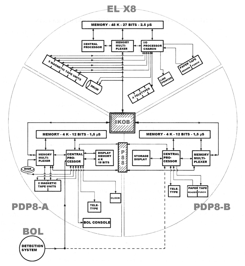
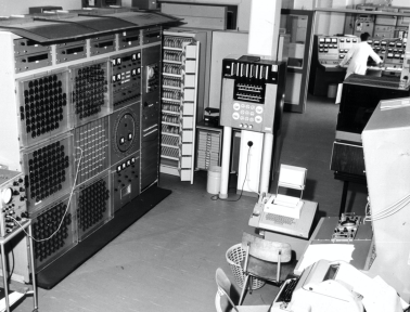
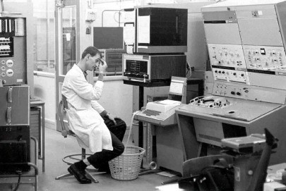
The installation of our X8 configuration303030The X8-configuration consisted of the basic unit with central processor (CRO), operator console, magnetic core memory 32k (later upgraded to 48k) 27-bit words (+parity bit) with cycle time 2.5s, a memory access multiplexer, Charon – the I/O processor, fast channel selector (SKK), Bryant magnetic drum with 512k memory of 27-bit words and a cycle time of 20 ms, real time clock/alarm clock, console for manual control, Siemens teletypes, line printer 1-5 lines/s and for paper tape: a 1000 ch/s EL1000 reader and a 150 ch/s Facit punch. started in late 1966 and was completed at the beginning of 1967 (Fig. 4). Thereafter, the machine was also integrated into the triangular BOL network with IKOB and the two PDP8s connected by the homemade interface P88 (Fig. 5).313131Oberski, Jona E.J., et al. (1971a) Electronics of the BOL System. Nucl. Instr. Meth. 92:177-187; Oberski, Jona E.J, L.A.Ch. Koerts, R. van Dantzig and K. Mulder (1967) Toelichting op de computers in BOL. IKO internal report Interiko 67/9. Archived at the National Museum Boerhaave, Leiden and at Nikhef, Amsterdam. https://ub.fnwi.uva.nl/computermuseum/pdfs/computersBOL.pdf. Shortly after, measurements with BOL were sent to the X8s and secondary data coming from the X8 appeared on one of the display units with which the PDP8s were equipped. From that time onward, adequate insight into the experimental situation and the quality of the measurements of the functioning BOL-system was available to the physicist overseeing the experiment. Our coupling of a complex nuclear physics detection setup to a computer network for the on-line control and data handling may well have been a European first.
The next three sections describe aspects of the innovations we designed or developed at IKO, partly in collaboration with Electrologica, on the computer side of our installation: the time-sharing operating system and the X8 and PDP8 software essential for the data-handling and analysis.323232Dantzig, René van, et al. (1971b) Analysis of multidimensional nuclear data (BOL). Nucl. Instr. Meth. 92:205-213.
The communication between the X8 and a PDP8 is to be set up as a series of block transfers, denoted ‘conversations’, that can be initiated by any of the three machines. Two types of sentences can occur in the conversations: ‘introductory sentences’ and ‘main sentences’. An introductory sentence is a short data block of fixed length and with a fixed format, providing information about at most one following main sentence. Main sentences have a variable length and structure. Charon always has at its disposal addresses in memory space, where current sections for input or output are located in all three machines. These memory sections are called ‘repositories’. If a machine wants to communicate with another machine by sending an introductory sentence, it offers a communication request to Charon, specifying the addressed machine. Charon then checks whether IKOB is ‘not busy’ and – if so – investigates whether the addressed machine gives ‘input permission’, implying that this machine has an input repository ready to receive a block transport. Then Charon arranges a data transfer through IKOB from the ‘output repository’ of the source machine to the ‘input repository’ of the target machine. The PDP8s have fixed repositories for input and output of introductory sentences. A flag (flip-flop/bit) in IKOB indicates whether the input repository is available. Transfers always involve an even number of PDP8-words of 12 bits being packed in 24 bits, on the X8-side fitted into a 27-bit word. The repositories in the X8 are chains of relocatable memory sections, connected by address pointers and provided with chain counters. When a subsequent request comes before the current repository is available, the next section in the chain is used. Upon a communication request, Charon reads the address of the repository and arranges the transfer. When the introductory sentence has been transferred in DMA-mode, with a word transfer counter in IKOB, the latter informs Charon with a dedicated flag. Also, if the X8 takes the initiative, a main sentence is handled by Charon only following a request from a PDP8. In that case, the PDP8 is ‘invited to invite’ Charon to send an introductory sentence with the required PDP8 details included. When a main sentence DMA transfer has been completed, IKOB notes this in this case, too, and informs Charon with a dedicated flag. Because, on the PDP8 (experiment) side, the available memory is restricted and speed is important, a single main sentence can be transferred in ‘stutter-mode’, implying that the transfer is split up in parts separated by a pause, such that the PDP8 can use the same memory section a number of times, thus saving space. The stutter mode does not allow the transfers to be checked rigorously and thus cannot be used if even an exceptional error cannot be tolerated, such as with transfers of programs. For measurement data from BOL, this mode is considered acceptable. The simplest and fastest mode is ‘unsolicited reading’ of PDP8 memory by the X8. In this case, as long as IKOB is ‘not busy’, the X8 can read a specific part of PDP8 memory (a section with measurement data) and is supposed to know how to handle the obtained data. Software drivers for IKOB are needed on both types of machines in such a way that data transfers satisfy standards already existing for the data streams to and from the magnetic tapes. This is important in order to facilitate data handling procedures independent of the specific input and output channels.
5 Time-sharing
Almost all computers in the 1960s relied on ‘batch processing’ or ‘unitasking’, where one job is executed after the other. ‘Time-sharing’ (TS)333333Time-sharing implies ‘multitasking’ and ‘multiprogramming’, but the converse is not necessarily true. In the latter cases, jobs submitted in batch-mode can overlap in time and in system resources, but there is not necessarily a possibility for multiple users working parallel to each other. The first Dutch application here was the ‘THE’-multiprogramming system developed by E.W. Dijkstra, where jobs are submitted in batch mode, but run as much as possible interleaved, to gain overall runtime., where a number of users can work in parallel, each of them having access to essentially all system resources, had been developed in the US. Worldwide, the first TS system became fully operational in 1961 at MIT in Cambridge. A little later, several TS systems in the US were described in the literature, but – as far as we know – no such systems were available in Europe at that time.
As installed, the X8 operating system, called ‘Monotor’, provided only batch processing. When, in the course of 1967, the system became intensively used, the shortcomings of batch processing were felt more and more. Often, time was lost with a change of user. Immediate high priority access to the computer was rarely possible, and conversational control of programs was hardly allowed, because it was considered inefficient and it would preclude access by another user for quite some time.
Fortunately, within one year, Pieter van Engen and Rolf Meesters of the IKO Software Group343434The IKO software group led by Pieter van Engen included Anton Mars, Rolf Meesters and Pim Biekman. developed a time-sharing system, called ‘Wammes’,353535Engen, Pieter G. van, and Rolf Meesters (1969) WAMMES, een time-sharing systeem voor de EL-X8: gids voor gebruikers. Archived at the National Museum Boerhaave, Leiden. https://ub.fnwi.uva.nl/computermuseum/pdfs/WAMMESgebruikersgids.pdf. which included a few parts of Monotor, such as magnetic tape drivers. On starting this project, the authors were inspired by the work of Edsger W. Dijkstra363636Dijkstra, Edsger W. (1968) The structure of the THE-multiprogramming system. Commun. ACM 11(5):341-346. https://www.cs.utexas.edu/users/EWD/ewd01xx/EWD196.PDF. on ‘semaphores’ and ‘mutual exclusion’373737Mutual exclusion for concurrent processes has been studied by Th.J. Dekker. to safely guide concurrent processes through‘critical sections’ that had the risk of – for example – a ‘deadlock’.
Wammes became fully operational in March 1969 and allowed users to load, assemble, execute, trace, stop and inspect programs simultaneously at each of the four terminals. The system and the programs it could handle were written in the X8 assembler macro-code ELAN. The assembly of a program resulted in a binary relocatable383838Upon assembly, the resulting machine program was, using a simple trick, equipped with ‘relocation information’ to be used at start-up time. file, which could be appended to the system library, including the program text. In the absence of discs, the file system was a mixed system of the drum and magnetic tapes. A user could create a file on the drum and dump it onto the central library, a magnetic tape, from which it could be retrieved later.
The system was based on a carefully operating swapping method. If possible, a program was loaded in an unoccupied core area or elsewhere on the drum. When a program in core memory was blocked, only the part that was needed for another program was swapped. Except for magnetic tape units, which a program had to reserve in advance for its own use, all other programs could use every input/output device virtually simultaneously. This was achieved by buffering the I/O data on the drum. A driver program corresponded to any output-device, selecting the next ‘closed’ file for actual output. Every program could use dynamic storage allocation routines which operated in the working space of the program.
One of the benefits was that the time necessary for programming was considerably reduced due to the editing, debugging and library facilities, making more time available to more users. The possibility to split and run a program in segments, as we developed for the PDP8 (see Section 7), and as often done in other TS systems, was not possible for the X8. Every program could only be relocated in its entirety.
Priorities and machine time allocation to logged-in users were essential. The starting point was the democratic principle that all users get the highest priority, and in turn, the same slice of processor time. However, there were a few other rules, too. For example, the response time at terminals was – as much as possible – within seconds. When a program was involved in semi-real-time data processing for the BOL experiment, it had ‘urgency priority’, which meant that it got all the processor time it needed and could get and would not be swapped out, unless manually by the operator. If there were two urgent programs, the first one received the highest priority.
An important software debugging facility, which came to full fruition in Wammes, was ‘dynamic program tracing’. It was available on our X8 exclusively, and originated from one of the early meetings with Electrologica, where we reported our positive experience with PDP8 program debugging using our own development of ‘tracing’ under dynamic supervision. We had discovered that a very simple trick made this possible and we asked Electrologica whether something similar could be done for the X8. The method, which we called ‘delayed self-interrupt’ (see Section 7), imposed only extremely simple requirements on the hardware. The program, while running, could be interlaced in time by a tracer-interrupt routine, operating in the background of the program. It turned out that a similar trick was also possible for the X8 and a program to be tested could run under the control of the programmable tracer, while after the execution of essentially any machine instruction,393939Only instructions executed within a system program, where the X8-interrupt was switched off, could not be traced, obviously. the status of registers and addresses could be checked on the basis of flexible criteria in the tracer interruption routine. In a report404040Note added to a brief Electrologica report by Th.R.C. Bonnema of a meeting end 1965, with present: Nossbaum, Seligmann, Bonnema from Electrologica, and Koerts, Van Dantzig and Oberski from IKO, with the title translated as: ‘Coordination facilities for a tracer’. of a BOL-Electrologica meeting, it was written that “This tracing facility would in the first instance be applied especially for IKO”.
Wammes was a ‘bomb-proof’ time-sharing system: all user programs ran in a mode where it was impossible to write outside their own memory space. This was realized thanks to X8’s top-of-the-line, hardware feature, write-protection to be set and cleared for blocks of 512 words by system routines running in kernel mode. Even if a user got stuck in a loop, there was a clock interrupt at the end of the current time slice to finish the user task.
The Wammes developers promised a bottle of good wine to the user who succeeded in ‘hanging’ Wammes. JEP de Bie, one of the physicists/programmers, accomplished this the next day with a program having a single instruction: ‘Program Boom; Loop: do Loop; end Boom’. The ‘do’ command executed the instruction indicated in the address field – in this case, this instruction itself. Thus a single instruction was trapped in an endless recursive loop, the system being immune for any clock interrupt. As a result, the ‘blinking lights’ on the console glowed continuously. The only recourse was to hit the on/off switch and do a full reboot. Apparently, this possibility had been overlooked in the hardware design by Electrologica. JEP de Bie thus got his bottle of wine. I am not certain whether Electrologica corrected this. Anyway, deliberately hanging Wammes was rewarded only once; it became banned and no such anomaly ever showed up in normal user programs.
When we consider Wammes from the user’s point of view, in principle we could start, pause and stop programs on the teletype as if the entire X8 were freely at our disposal. Mostly, that worked out well, although it could happen that the system refused a program because it would need too much drum memory or tape units, some of these having already been reserved by other users. Basic characteristics of time-sharing systems, such as the parallel use of peripherals by different users and the simultaneous use of both the foreground and a background memory, were clearly present. The goal, to build a system that could efficiently run essentially the same programs as in batch mode, had been realized. The X8 with Wammes became a more pleasant and better manageable machine.
6 Developing data reduction and analysis software
Soon, we became strongly committed to the design of an overall data reduction system that would be as simple as possible, and could flexibly be programmed without complications from I/O. To achieve our goals, we would ‘mold’ our event data into a universal structure according to a set of rules, the ‘BOL format’. The main idea was that the data structure would have ‘levels’ in substructure and that operations at the various levels could be programmed separately, independent from where they came and where they would go. Once in this BOL-format, the events could be subjected to several user-programmed ‘passes’ with checks, alterations, rejections, selections, and calibrations, ending up on tapes as experimental sets of ‘validated data’.
All data were supposed to remain in accordance with the format during all the processing. The BOL format had seven levels of nested data subsets, ‘quanta’ of information.414141Dantzig, René van, et al. (1967a) Kwantisering van infostromen: draft. Archived at the National Museum Boerhaave, Leiden. For primary BOL data at the deepest level, the elementary quantum was a ‘record’, specifically, an ‘event record’ that contained data from a measurement of one or more detected particles resulting from one collision. At the next level, and only for practical reasons,424242Memory buffering and writing on external media like magnetic tape. a number of records were packed in a ‘block’ (without a particular meaning). A series of records (in blocks) would combine into a ‘train’; trains into a ‘net’; nets into a ‘group’; groups into a ‘file’; and finally, files into a ‘repfile’. Trains, nets, groups and files were separated by special blocks. Different quanta were meant to have a specific meaning. For instance, a train (of blocks of records) might contain homogeneous data, measured under exactly the same experimental conditions. A net (of trains of blocks of records) might correspond to the same target with different beam conditions. The largest quantum at the highest level was a ‘repfile’, a series of files, representing all data from one full experiment.
To obtain an overview and analysis of what was measured, we would have to ‘bundle’ validated event data. Bundling meant that certain combinations of values derived from the event data were ‘sorted and counted’ on a multi-dimensional (mD) grid in order to produce mD ‘spectral arrays’,434343A train represented a 1D array, that was a row of array records (0D-arrays), a net, a series of trains (1D arrays, rows, or a single 2D array), a group, a series of nets (2D arrays, or a single 3D array), and a file, a series of groups (3D arrays, or a single 4D array). ‘spectra’ for short. A spectrum was characterized by the numbers and the widths of the mD grid cells, together with the number of counts collected in each cell. The coordinates corresponding to the central values of the grid cells represented derived ‘physics values’.444444For experimental data, the ‘physics values’ are derived from measured values. For all experiments it is common to produce event data by a Monte Carlo (MC) random sampling method according to a theoretical model and all experimental effects taken into account. These MC-data are handled like experimental data and thus also can deliver ‘theoretical values’, to be compared directly with their experimental counterparts.
The BOL format was defined in such a way that it could be used for spectral arrays as well, to make these suitable for our standard data processing. An array element then became an ‘array record’, a row of the array became a train, a column of rows became a net, and so on. A file thus could embody a series of 3D-arrays or a 4D-array. For event data, the sequence of quanta within their next higher quantum was irrelevant, while for array data, this sequence was fixed by the positions (coordinates) in the array.454545Therefore, ‘array quanta’ to be rejected could not be removed, but at most administratively invalidated.
In that same design phase, we realized that for our anticipated measurement accuracy (-), the size of mD arrays, in whatever representation, would be far too large to be stored in their entirety in the X8 core memory. However, we could use the drum memory, which was 16 times larger! It was helpful that the number of counts in large spectral arrays would often be low in average and distributed in-homogeneously, crowded in relatively small regions (peaks or mountain ranges) and almost or completely empty in large regions, partly even by definition.464646In many spectral arrays, the kinematics of the reaction restricts the coordinate regions that can be occupied by event counts at all. High resolution would be only relevant in regions with good statistics. With this in mind, together with Electrologica, we made specifications for array-handling on drum store, allowing declaration and manipulation of groups of flexibly sized 3D-arrays with array elements of 3, 6, 12 or 24-bit bites. In cases where small bites would be chosen, a certain percentage of the array elements was allowed to ‘overflow’. This was taken care of by successively assigning larger bites in a reserved overflow area.
As opposed to the basic distributive474747In general, the most compact build-up and storage of spectra can be ‘distributive’ or ‘associative’. In the distributive – conventional – case, the memory space for the spectrum is completely and regularly structured beforehand such that all cells can be addressed directly given the coordinates. structure, the storage of these elements was associative.484848In associative storage, the structure in memory space is formed during the build-up and depends on details of the spectrum. Then, the coordinates of a cell are stored in an associated manner, i.e., together with – or pointing at – the cell content. At read-out, these cells were to be picked up together with the non-overflow elements in order to form the whole spectrum. A smart buffering and synchronization mechanism494949The method amounted to a) temporarily keeping the coordinates of the addressed array elements in core memory buffers that were associatively sorted according to drum tracks; b) asynchronous transport of drum tracks to core memory and vice versa, giving highest priority to the tracks with most modifications. Access rates of 104 per second were achieved. was necessary to read and modify the content of the drum addresses in an optimally efficient way.
Based on the above ideas, Electrologica started to build the corresponding software layer, a package of subroutines that would take the format and structure rules as given and provide the appropriate basic functionality for the data processing for all future BOL experiments. This layer was called the ‘Window system’ for the X8 (we here call it ‘WSX’),505050In Section 7, a simplified Window system for the PDP8 (WSP) is introduced. and the specifications were finalized with Electrologica in 1966.515151Dantzig, René van, et al. (1967b) Window-processing for on-and off-line data-handling: draft specifications. Archived at the National Museum Boerhaave, Leiden.
The Window system with the drum array layer including documentation became available525252WSX was realized by Stef Toenbreker, Pieter G. van Engen and Hans Suys from Electrologica. in 1967.535353Dantzig, René van, and Stef Toenbreker (1968b) Vensterprogrammering. Archived at the National Museum Boerhaave, Leiden. From that moment on, it was central in our data processing. In the user programs (‘passes’), data could easily be split, switched, and mixed between different I/O channels, and the programming was concentrated in ‘windows’ at separate structure levels, dealing with the various information ‘quanta’ described. The data at a given level would pass along the program window for that level. Program windows would only be opened for levels that were relevant in the current processing. A program window could read, alter or reject a quantum of data before sending it to one or more output channels. ELAN was used to write both the system routines and the user’s programs. From that moment on, essentially all BOL data-handling was programmed and run in WSX.
Even with the above-mentioned arrays on the drum, we thought that we would be unable to reach our overall required ultimate resolution, not even for only 2D array spectra. Therefore, together with Electrologica we made specifications for an additional package, called ‘counting in trees’ or ‘associative counting’. In this approach, 2D-trees, with a resolution consistent with a grid, would be built up beginning in core memory and continuing on drum storage. The tree structure was defined so that each leaf of a tree contained an end node or maximally 4 pointers (2 for each dimension) to other leaves, each pointer corresponding to the value of a certain bit in both coordinates.
Since each coordinate had a maximum of 12 bits, at most 12 pointer levels would be needed to reach non-zero counts cells. In principle, an arbitrary number (maximally 32) of trees could be built simultaneously, restricted by available drum space. It was, all in all, a quite complex framework. A buffer and synchronization technique, algorithmically even smarter than for the WSX-arrays on drum storage, was made. The package was delivered by Philips-Electrologica545454In 1968, Electrologica was taken over by the Philips company. in 1969,555555. but there were challenges to its use. The package was large, complicated to handle and slow. Moreover, at that time we could already solve our problems with the available software and the required resolution was less than anticipated. If my memory is correct, despite the good work, this package may have been an instance where our ambitions were too high.
Within WSX, spectra could be sent to an output medium, or immediately further analyzed. The spectra could have peaks, valleys, flat parts, and empty parts, all of these together constituting the ‘spectral structure’ for the chosen parameters and the chosen grid. Here, for the first time, we could judge whether the measurements looked comprehensible, and hopefully correct. If not, we had to go back to the data conversion passes and look for a possible explanation. When the validated data looked fine, the next crucial step could be taken, the identification of the detected particles (see the box in Fig. 7).
Measurements from the BOL detection telescopes had been calibrated and converted to the parameter values, (detected particle energy) and (energy loss in the checkerboard detector). These parameters were characteristic for whether a detected particle was of the type proton, deuteron, triton, (He-3) or (He-4) particle. In an versus spectrum approximately parallel mountain ranges would appear, each range – if present – belonging to one of the particle types. The particle identification required the contours of the mountain ranges to be outlined and then made available to a new pass of event data. There, using these contours, we could determine for each event the type(s) of the detected particle(s), including the type: ‘unknown’, in case the particle(s) fell outside all contours. The unknown type could sometimes be resolved later using other information. From this point onward, physics definitely came into the picture! Suddenly, we could select a particular nuclear reaction process and study that in detail, by now bundling the data to the most meaningful representations. These were real physics results, energy spectra, angular distributions or correlations, and the like for a specific nuclear reaction. They could be interpreted, studied and compared with theoretical model predictions. A selection of these results would appear in our publications.
In our team, a conversational program language, ‘Simplex’,565656Simplex was developed by Bob J. Wielinga from the BOL team. influenced by Algol-60 had been developed for calculations within the WSX framework. This was particularly important in the final stage of the BOL data reduction and data presentation, where we wanted to easily and flexibly apply our instrumental and physics insights to prepare pictures for further study or for publication. Spectra could be presented on a graphics storage display with hard-copy read-out connected to a PDP8 (see Section 7). A useful extension of Simplex was the Lisp-based program Lisi,575757Lisi was developed by Theo F. de Ridder from the BOL team, who had installed and extended the LISP program of Van der Poel and Van der Mey. which provided facilities for the graphics display with formula manipulation and symbolic processing of complex display structures.585858Theo F. de Ridder (1972) LISI, een LISP-SIMPLEX systeem met display faciliteiten, Informal IKO report. Archived at the National Museum Boerhaave, Leiden.
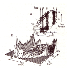
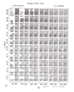
For their physics interpretation, BOL results needed to be compared with theoretical model predictions. Mostly this meant that, assuming the validity of the model, we had to perform a full Monte Carlo computer simulation of the experiment, taking into account the detailed measurement situation, including all the mounted and correctly working detection units. Because of rotational symmetry around the beam axis, there was a lot of measurement redundancy, largely compensating for missing detection units (see Section 8). When considered individually, our data were often less accurate, both statistically and systematically, compared to measurements performed elsewhere with fewer detectors. However, they covered almost all of the kinematical final states of the nuclear reaction under study in a continuous way. And that was unique! As foreseen, this was particularly important for the study of ‘few body reactions’. A discrepancy with simulated data would indicate ‘that’ – and often ‘where’ – the experiment showed deviations from the theory. A notable example was a comparison in full 4D between an experiment and a theory simulation (Fig. 8).595959Blommestijn, G.J.F., R. van Dantzig, Y. Haitsma and R.B.M. Mooy (1981) The reaction measured with BOL at MeV. Nucl. Phys. A 365:202-228.
The results obtained might clarify a known problem, but often new questions arose, leading to a follow-up experiment to shed light on the new questions. For the planning of new experiments, a crucial program606060This program was developed by Ton Ypenberg from the BOL team. in Algol-60 was developed, applying relativistic kinematics for nuclear reactions.
7 Software for minicomputer network nodes
The hardware and software functionality of the two network PDP8s (A and B) was very relevant in the X8 context. Our program developments for the PDP8s in the assembly language PAL/8 were of importance for choices in the X8 software and vice versa. Since interrupt handling was primitive for the PDP8 and we were starting on a basic programming level, in the interaction with peripherals, we worked with ‘waiting’ for a ready ‘flag’616161A flag was a ‘flip-flop’ (bit) that could be set (1) and reset (0) externally and/or programmatically. It could be sensed by a PDP8-instruction: if flag is set, skip next instruction. When properly programmed, it could also give a program interrupt. of each equipment, with one exception: tracing. An operating system, called Monikor, was built by us, physicists, around a linked list, containing all active waiting points and the corresponding values in the accumulator register, which also had to be restored as soon as the program was continued. Thus a compact and primitive multitasking system was created, without the use of interrupts, which – with later I/O extensions – transferred all measurement data from the BOL system for many years to magnetic tape and/or to our X8.
The Monikor system enabled dynamic storage allocation, binary program allocation, multi-job processing with time sharing and memory sharing, asynchronous data streams with semaphore mechanisms, dynamic program tracing, and a computer-computer (AB) conversational scheme. Compared with the software available for minicomputers at the time, most of these mechanisms were state of the art.
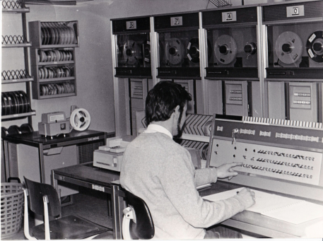
In our network, PDP8-A took care of reading the events from BOL, while including information from the physicist on duty, putting the data in the BOL-format, writing them on tape, and/or sending them to the X8 and/or to the autonomous display (Fig. 9) with ‘light pen’.626262When the light-sensitive pen touched the oscilloscope screen at an illuminated point, its electric pulses could be matched with register values determining the position of that point. These values could then be read out by the PDP8. Some changes to a M(emory)-unit of a kicksorter636363A 512 channel Nuclear Data 130 Analyzer, where the least significant 12 bits were used for data and the 6 most significant bits for logic functions like interrupting the PDP8, display permission, display intensifying or light pen flag. with help from Philips NatLab had made it possible to operate all previously manually steered functionality of the display by direct computer control of PDP8-A. With the light pen, we could mark channels independent of the PDP8. An interface between the M-unit and the display oscilloscope allowed ‘contour’ and ‘isometric’ 3D-display modes. In the latter case, this was achieved by turning the viewing angle around. Also, it became possible to make selections on channel address and/or channel content as well as to adjust the light intensity of each displayed point based on the memory content. A little later, a storage oscilloscope646464Tektronix Storage Oscilloscope Type T611. All interfacing (BOL detector, tape units and display units) was done by the IKO digital group led by Evert Kwakkel, which included Pier ten Kate, Jan Kraus, and others. with hard copy read-out was interfaced to PDP8-B, thus making it the main display facility.
The PDP8’s memory consisting of 32 ‘pages’ of 128 words of 12 bits, allowed direct addressing within the same page. Memory sharing of asynchronous programs required a suitable dynamic storage technique. We divided the core memory into two regions of pages: the free region and the occupied region. The boundary between them was dynamic and in fact, the regions could overlap each other page-wise. The administration contained a list of page-status words. Two functions controlled the memory sharing administration: ‘get-page’ and ‘put-page’. Their calls had to be paired off, so that every job would finish only after giving up all space reserved during runtime.
Whenever a job program was loaded, it obtained the needed pages. The loader program itself was also a job program, active in parallel with other programs. Successively allotted pages were, in general, not contiguous. In order to use the dynamic storage allocation mechanism for programs, we had to allow programs to be relocatable by page rather than by program. We restricted references to other pages to jumps and subroutine calls. This was a limitation we could work with, while the relocation method could be straightforward and the formats could remain standard.
The format of data streams that have been implemented for the X8, as described in Section 6 in terms of the info-quanta (record, block, train, net, group, file, repfile), required a similar – though simplified – window processing layer (WSP) for the PDP8s. For this purpose, a general input-output file handling system, 656565Biekman, W.C.M. and Anton J. Mars (1968) PDP-8 IN-UIT-systeem. IKO informal report. Archived at the National Museum Boerhaave, Leiden. tailored to the Monikor system, was built by our software group. This system covered all information channels like the BOL set-up, tape units, the display units, and the X8. Interacting asynchronous input- and output-processes could ‘switch’ information at the file level between one input channel and an arbitrary set of output channels. The data stream, which was divided into the info-quanta, could pass ‘window programs’ as described for the X8. Specified at the highest protocol level, these could inspect and operate upon the data between input and output. Different I/O processes could run simultaneously, while output jobs waiting for input information did not take up processor time. Synchronization was accomplished using I/O semaphore-functions: the WSP system turned out to be sufficiently flexible and powerful.
As brought up in Section 5, the X8 tracer had been made in accordance with our simple method for the PDP8, the ‘delayed self-interrupt’. It consisted of an external interrupt inducing flag (bit), which was cleared at the entry and set before the exit of a tracer interrupt subroutine, the latter with an intrinsic delay of about . The delay time was chosen so that only one instruction of the program under tracing could be executed, at the completion of which, the flag provided a new program interrupt. While tracing a program, the interrupt subroutine (possibly adapted to personal needs) could, for example, cause a stop when the content of a selected register or memory address satisfied a preset condition. This provided an excellent new test facility for the in-house software development.
Around 1970, inspired by the design of Wammes and experienced in building the PDP8 Monikor and WSP-system, Anton Mars, Jan Visschers and Ruud van Wijk developed a genuine time-sharing operating system AIDA666666AIDA = Algemeen Interactief Data-analyse systeem. for a PDP8. I think, this was unprecedented for such a small machine. It could serve up to 12 users with time and memory sharing through alphanumerical terminals. Since the PDP8 was interfaced to the X8, these terminals also could serve programs running under Wammes, thus extending the number of simultaneous X8-users. Relocatable user programs, as described for Monikor, could be controlled and run independently and simultaneously on the PDP8. All this could be realized thanks to a hardware extension to the PDP8-processor, a memory protection unit, designed by the IKO digital group with specifications from the software group. This unit functionally blocked I/O- and halt-instructions as well as all memory reference instructions, writing outside certain dynamically specifiable areas of core memory. Upon occurrence of such a blocking, an interrupt was generated, enabling the operating system to take appropriate action. AIDA brought considerable satisfaction for the programmers as much as for the users. It has been used until the DEC-system 10 came into view.
Practically all of the PDP8 software mentioned above was reported at meetings of the Digital Equipment User Community (DECUS) Europe in 1968676767Dantzig, René van, et al. (1968a) Recent hardware and software developments for the PDP-8. Proceedings of the 4th European DECUS Seminar (1968). Archived at the National Museum Boerhaave, Leiden and at Nikhef, Amsterdam. See also https://ub.fnwi.uva.nl/computermuseum/pdfs/RecentHardwSoftwPDP8.pdf and in 1972.686868Mars, Anton J., J.L. Visschers and R.F. van Wijk (1972) AIDA – An operating system for the PDP-8. I. Software. Proceedings of the 8th DECUS Europe Seminar 1972. Archived at Nikhef, Amsterdam; Kate, P.U. ten, and E. Kwakkel (1972) AIDA - An operating system for the PDP-8. II. Hardware. Proceedings 8th DECUS Europe Seminar 1972. Archived at Nikhef, Amsterdam.
8 Final considerations and conclusions
Over three decades the Philips Company and IKO had an invaluable collaboration, that included construction and support of the cyclotron, support on building and maintaining an electron accelerator as well as the development and production of nuclear detectors.696969. All articles in this issue.
The Mathematical Center, meeting the growing computational requirements at IKO in the first half of the 1960s, was essential. The access to the X1 allowed IKO physicists and technicians to complete practically all of their computer work, amounting to many hundreds of hours each year.
The continuation of the MC computer developments within Electrologica led to the production of a substantial series of X8 machines, one of which found its way to IKO. To obtain the funding, our institute had a strong hand with the portfolio of its cyclotron, the 85 MeV linear accelerator, a much more powerful 300 MeV electron accelerator in the planning stage, and last but not least the immediate needs of the BOL project. Equally compelling was that Electrologica, as the first Dutch computer manufacturer, produced a first-class computer and had the ability and willingness to provide the necessary IKO special hardware and software at reasonable costs.
The X8 made it possible for us to dive into the then modern programming developments and, together with Electrologica, to create an avant-garde online network with data processing software. Programming in ELAN gave us great satisfaction because of its structure and power. In our view, this assembly language was very well thought-out!
The IKO software group, which was created with the arrival of the X8, was as enthusiastic and ambitious as we, the physicists and hardware technicians, were. A major result was Wammes. Time-sharing became indispensable for all of us in many respects. It gave us ample opportunity to ‘get at the machine’, not only in cases of experimental urgency, but also for efficient analysis as well as program development and online testing. Moreover, it allowed us to learn and employ new techniques, such as list-processing and formula manipulation, thereby accelerating and improving our work. Wammes may have been the first fully operational time-sharing system in Europe. Although only tailored to EL-X8-computers, Wammes was in several respects comparable to the AT&T Unix operating system which came into worldwide use a few years later.
There were no significant problems in building and operating the BOL network. This was quite remarkable, since there were two suppliers, the Electrologica staff involved on the X8 side, and IKO (the BOL-team), on the PDP8 side. The two groups made an excellent match!
In the end, what really counted was the data processing and analysis. Of the main software packages programmed by Electrologica, the X8 Window system was the most general and indispensable one. It consisted of a set of subroutines and rules that could have been programmed in any computer language. The fact that there was no future for Electrologica, for Wammes and for the Window system is regrettable. On the other hand, we were early workers on – in contemporary jargon – ‘big data’ and ‘data mining’. That some of us then already got the opportunity to learn and apply early ideas of ‘Artificial Intelligence’ (AI),707070An ‘Artificial Intelligence’ study group was formed by, among others, Bob Wielinga and Theo de Ridder. Bob Wielinga became a professor at several universities, well known for his AI research on the methodology of knowledge-based system design and knowledge acquisition. is notable, considering that the three areas are now, half a century later, strongly intertwined.
After having learned about the many positive things of BOL, one might wonder if everything was really so exciting and successful. Of course, there were setbacks and challenges. Parts of the project took much longer than foreseen or were not realized at all. The cyclotron beam was less intense and could not be focused on targets as well as had been anticipated. The complexity and size of the electronics required very time-consuming maintenance. We always had a number of detection units missing, because they were being repaired, or subtle errors turned up when mounted units were checked. However, we could live with this, thanks to a lot of redundancy in the measurement space and – importantly – by comparing the experimental data with adequately simulated theoretical data. In spite of the many problems, the whole concept of BOL worked; the results, often multidimensional, set a new standard and were fascinating! To report on our multidimensional results in articles and at conferences in a way comprehensible to colleagues not familiar with BOL, made that we had to develop special ways of presentation.717171On this we got advise from distinguished colleagues, in particular prof. Ivo Šlaus, from Zagreb University.
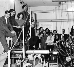
We, physicists of the BOL team (Fig. 10), had a mood and attitude, that somehow belonged to the 1960s: everything was possible or at least should have been possible! That meant freedom and cooperation in daring experimentation in physics, electronics and programming. It also meant being smart, working hard and with dedication, and doing night shifts at the cyclotron or on the computer after a full day of work. We were eager to work at the forefront of science and technology, we read a lot of professional literature and we had our own colloquium and working group. There was a lot of liberty in choosing the subjects of learning and of experimentation, even if the connection to the project was uncertain. We became accustomed to ‘out of the box’ thinking. Occasionally, some of us spent evenings and nights together and with friends, listening to contemporary pop music, while fleeting romances could arise with wine and cannabis as catalysts. In summary, I believe that the multifaceted open-minded spirit of our team contributed a great deal to the BOL project’s success, on top of the acquired expertise, and, to be honest, quite a bit of good luck, too.
It was in 1971 that we, the BOL ‘triad’, Karel Mulder, Jona Oberski and I, in a full afternoon marathon ceremony at the University of Amsterdam, successfully defended, one after the other, our Ph.D theses with BOL results. Our experimental work continued until 1973, when the measurements were stopped. A total of nearly 2,000 data tapes remained. The data analysis was continued mainly by three graduate students and several undergraduates. The following year, the X8 was replaced by a model 10 computer from Digital Equipment Corporation (DEC).727272Dantzig, René van, et. al. (1973) Voorstel tot vervanging van de EL-X8 computer configuratie van het IKO. Archived at the National Museum Boerhaave, Leiden. https://ub.fnwi.uva.nl/computermuseum/pdfs/X8vervanging.pdf; Wielinga, B.J., J.E.J. Oberski, R. van Dantzig et al. (1973) Toelichting op de aanvraag voor vervanging van de rekenmachine van het Instituut voor Kernphysisch Onderzoek (IKO) te Amsterdam. IKO informal report. Archived at the National Museum Boerhaave, Leiden. https://ub.fnwi.uva.nl/computermuseum/pdfs/vervanging1973.pdf. The main functionality of the X8 software was reprogrammed in Fortran by staff from DEC. Analysis and preparations of publications continued officially until 1977. Our last publication appeared in 1982.737373Blommestijn, e.a. (1981). The BOL project might be summarized as a difficult and successful undertaking, with most of its significance at the forefront of few-body nuclear physics. It led to twenty publications in international scientific journals, three patents, six PhD-theses, as well as many master’s theses, conference articles, and laboratory reports.
As a whole, BOL with its full infrastructure can be viewed as an early precursor of modern particle physics set-ups, with its 4-type detection ‘all around’ the collision region, with its silicon detectors for ‘accurate’ impact position measurements, with its ‘large’ number of electronic channels, with a computer network online to the experiment and sophisticated software. All of these qualities are, in extremely scaled-up and improved fashion, characteristics of current high-energy particle physics experiments.
In 1977, the BOL detector was placed as a ‘monument’ on our campus and stayed there for 25 years (Fig. 11). Shortly after the turn of the century, it was dismantled and the heart of the system with examples of its main elements were exhibited at Nikhef in a showcase with a continuously running presentation until 2016. In that year, the BOL remnants and our corresponding archive were transferred to the Dutch Science Rijksmuseum Boerhaave in Leiden. That same Museum decided in 2018 to also include an X8, which had been kept elsewhere,747474This X8 had been operational at the University of Kiel, Germany. in the collection. It feels good that, now, a half-century later, our BOL and an X8 have been saved for posterity, together.
Acknowledgement
Much of the chronological framework of this article could be retrieved thanks to IKO
and FOM annual reports. The black-and-white photographs from the BOL-period, shown
here, were taken by Hans Arnold. I am very much indebted to my former colleagues
from the X8-period and BOL period, who shared with me their recollections and
provided useful comments on versions of this article, in particular JEP de Bie,
Gerard Blommestein, Theo Bijvoets, Pieter van Engen, Anton Mars, Jona Oberski, Henk
Peek, Theo de Ridder, Ton Sonnemans and Jan Visschers. I am especially grateful to
David van Dantzig and Zachary Tobin for textual improvements.
I feel honored to have been invited by Gerard Alberts, editor of the Springer
series History of Computing, to compose this article.
This review is dedicated to the memory of my dear brother Émile C. van Dantzig,
who started his career in information technology with the X8 at the Mathematical
Center in 1968 and moved to IKO in 1972, where he enthusiastically and skillfully
managed the X8 and the succeeding DEC system-10 until 1979.