Improving the stability of frequency dependent squeezing with bichromatic control of filter cavity length, alignment and incident beam pointing
Abstract
Frequency dependent squeezing is the main upgrade for achieving broadband quantum noise reduction in upcoming observation runs of gravitational wave detectors. The proper frequency dependence of the squeezed quadrature is obtained by reflecting squeezed vacuum from a Fabry-Perot filter cavity detuned by half of its linewidth. However, since the squeezed vacuum contains no classical amplitude, co-propagating auxiliary control beams are required to achieve the filter cavity’s length, alignment, and incident beam pointing stability. In our frequency dependent squeezing experiment at the National Astronomical Observatory of Japan, we used a control beam at a harmonic of squeezed vacuum wavelength and found visible detuning variation related to the suspended mirrors angular drift. These variations can degrade interferometer quantum noise reduction. We investigated various mechanisms that can cause the filter cavity detuning variation. The detuning drift is found to be mitigated sufficiently by fixing the incident beam pointing and applying filter cavity automatic alignment. It was also found that there is an optimal position of the beam on the filter cavity mirror that helps to reduce the detuning fluctuations. Here we report a stabilized filter cavity detuning variation of less than 10 compared to the 113 Hz cavity linewidth. Compared to previously published results [Phys. Rev. Lett. 124, 171101 (2020)], such detuning stability would be sufficient to make filter cavity detuning drift induced gravitational wave detector detection range fluctuation reduce from to within .
I Introduction
Advanced gravitational wave detectors, such as Advanced LIGO aasi2015advanced , Advanced Virgo acernese2014advanced , and KAGRA aso2013interferometer , are designed to be quantum noise limited over most of their sensitivity spectrum. During their third observation period, the phase quadrature squeezed vacuum was successfully utilized in LIGO and Virgo, enabled a 3 quantum noise reduction above sub-100 Hz acernese2019increasing ; tse2019quantum . However, at the same time, the low frequency quantum noise originating from amplitude quadrature vacuum fluctuation was increased due to the Heisenberg uncertainty principle and approached the limit of the low frequency noise budget buikema2020sensitivity ; acernese2020quantum ; yu2020quantum . Thus, a broadband quantum noise reduction becomes indispensable for further sensitivity improvement, and requires the use of frequency dependent squeezed vacuum kimble2001conversion . Squeezed vacuum can obtain frequency dependence by reflection from a detuned optical cavity, called filter cavity. For advanced gravitational wave detectors operating with tuned signal-recycling cavity, one filter cavity having hundred Hertz linewidth and half-linewidth detuned is optimal purdue2002practical ; khalili2010optimal ; evans2013realistic ; kwee2014decoherence . Below 100 Hz, phase quadrature squeezed vacuum will be rotated to the amplitude quadrature, while high frequency squeezed vacuum is unchanged. Frequency dependent squeezed vacuum sources were developed in prototype zhao2020frequency ; mcculler2020frequency and will be used for the upcoming observation runs of Advanced Virgo+ flaminio2020status , aLIGO+ barsotti2018a+ and KAGRA michimura2020prospects . To operate an optical cavity, the laser frequency fluctuation and/or cavity mirrors’ differential motion need to be controlled so that the cavity prompt reflected light can have a fixed phase difference with the light that enters, circulates and is leaked back from the cavity. When this phase difference is kept to be , we say that the cavity is locked on resonance. But when this phase difference is held at an offset from , we say that the cavity is locked with a detuning. In our experiment, the filter cavity length stability necessary for frequency dependent squeezing is achieved using an on-resonant 532 nm (green) beam, which is a harmonic of the 1064 nm (infrared) squeezed vacuum wavelength. The technique of controlling a laser beam’s frequency using its own harmonic is referred to in this paper as bichromatic length control, and has been used for filter cavities oelker2016audio ; zhao2020frequency , optical parametric oscillators (OPOs) vahlbruch2016detection ; stefszky2010investigation , and arm length stabilization of gravitational wave detectors akutsu2020arm . However, initially, using bichromatic length control yielded a filter cavity detuning stability of the order of 30 Hz zhao2020frequency while the final goal is to achieve 1 Hz stability aritomi2020control .
In this paper, we study and identify the origin of the detuning drift and we demonstrate how to reduce it to a level compatible with the requirement of gravitational wave detection. Section II shows the experimental setup used to produce frequency dependent squeezing. Section III outlines the mechanisms of sources of relative detuning drift for green and infrared beams. Section IV gives the results of measurements performed on the most prominent sources of relative detuning drift. Section V shows the end result of improving the detuning stability of the filter cavity. Section VI discusses the implication of the improved results in the context of detection range of representative gravitational wave sources.
II Experimental setup
The experimental setup required to generate and characterize frequency dependent squeezing is introduced in our previous work zhao2020frequency . In this paper, we focus on the detuning stabilization using newly implemented bichromatic control of filter cavity alignment and incident beam pointing. A simplified scheme of the experimental setup is shown in Fig. 1. Some important parameters of this filter cavity setup are summarized in Table. 1.
| Parameter | Symbol | Value |
| Length | L | |
| Mirror radius | R | |
| Input mirror radius of curvature | ||
| End mirror radius of curvature | ||
| Parameters for 532 nm beam | ||
| Input mirror transmissivity | 0.7 % | |
| End mirror transmissivity | 2.9 % | |
| Finesse | 172 | |
| Beam radius at input mirror | 7.26 mm | |
| Beam radius at end mirror | 7.35 mm | |
| Parameters for 1064 nm beam | ||
| Input mirror transmissivity | 0.136 % | |
| End mirror transmissivity | 3.9 ppm | |
| Finesse | 4425 | |
| Beam radius at input mirror | 10.26 mm | |
| Beam radius at end mirror | 10.40 mm | |
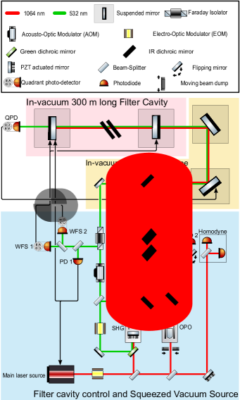
The main laser beam is split into three paths, one is used to pump the second harmonic generator (SHG), another is used as bright alignment beam, and the last one is used as local oscillator in homodyne detector. Additionally, the green beam is split into two paths: one is used for filter cavity bichromatic control and the other pumps OPO for squeezed vacuum generation. In the bichromatic control scheme, we use the green beam to control filter cavity length, alignment and incident beam pointing. The Pound-Drever-Hall technique black2001introduction is used to extract the cavity length error signal at PD 1 in reflection of the filter cavity. The cavity length correction signal is split into two frequency bands: the part below 10 Hz is sent to the filter cavity end mirror position while the part above 10Hz is sent to the main laser frequency. Automatic alignment control uses two wavefront sensing quadrant photodiodes in the filter cavity reflection and acts on cavity mirrors’ angle to keep the filter cavity axis aligned with the incident beam. (See Supplement Material Note1 first three sections for details of an optical cavity misalignment and the wavefront sensing automatic alignment implementation.) Incident beam pointing control is achieved using an error signal extracted from a quadrant photodiode in the filter cavity transmission and actuated on the angle of an in-vacuum suspended steering mirror in the filter cavity injection path. The green and infrared beams are overlapped by a dichroic mirror located before the pointing control steering mirror. Thus, alignment and pointing controls act on the co-propagating green and infrared beams. However, prior to the dichroic mirror, the green and infrared optics can move, causing a relative drift of alignment. A misalignment of few percent (in terms of power coupled with higher order modes) arises after several days.
An acousto-optic modulator located on the green beam going to filter cavity shifts the frequency of the green beam by the amount of a driving signal. In this way, after the green beam is locked on resonance for filter cavity, infrared detuning can be precisely adjusted by changing driving signal frequency.
The bright alignment beam resonates in the OPO, and the transmitted component has the same shape and propagation path as the squeezed vacuum. Meanwhile, bright alignment has phase modulated sidebands and is demodulated after its reflection from filter cavity. The acquired Pound-Drever-Hall signal allows us to investigate filter cavity detuning drift.
When beam dumps and flipping mirrors are changed in Fig. 1, squeezed vacuum is generated from OPO and obtains frequency dependent quadrature rotation after reflection from the detuned filter cavity. The homodyne detector is used to characterize the frequency dependent squeezing.
III Filter cavity detuning drift mechanisms
In bichromatic controls, in order to have a stable detuning for infrared, the green beam frequency change must be a factor two of the infrared beam frequency change. In addition, the green beam must be kept on resonance. However, many effects are involved in the experiment to change the filter cavity resonant condition, which are introduced in this section.
III.1 Filter cavity length/laser frequency drift
An optical cavity needs to be locked to provide a stable amplitude/phase/mode-shape filtering for its incident light. A suspended cavity lock will be acquired if the control system can be engaged fast enough when a resonance is crossed, while it will be lost if a disturbance happens so that the control system cannot provide large enough correction barsotti2006control . However, in the filter cavity bichromatic control, even during lock, there is residual drift of the cavity length and laser frequency that can influence the filter cavity detuning witnessed by the infrared beam. In addition to in-lock detuning drift, shift of the filter cavity detuning can also occur when the filter cavity loses lock. In the case of lock loss and re-acquisition, we find that only cavity length drift has contribution to the detuning variation.
Detuning drift when the cavity is kept locked.—During lock, the control system is working to compensate for residual filter cavity length drift by changing the laser frequency to hold resonance. There is a corresponding laser frequency shift of:
| (1) |
where f is the laser frequency and L is the filter cavity length. The green beam frequency change is thus:
| (2) |
The green laser frequency before entering the filter cavity is , where is the green beam wavelength () change induced by AOM, c is the speed of light. Since the green beam is generated as a second harmonic of light from main laser, the infrared main laser frequency change is half of Eq. 2. However, as seen in Fig. 1, when the setup is configured to generate squeezing, the OPO is pumped by green light sampled prior to the AOM. As such, the frequency of squeezed vacuum is half that of green prior to entering the AOM, which is the same as the frequency of main laser and thus the bright alignment beam. This is the reason why monitoring the bright alignment beam can predict the frequency behavior of squeezed vacuum. However, since the frequency of squeezed vacuum doesn’t involve AOM, a frequency change of half of Eq. 2 without is required to maintain the resonant condition for squeezed vacuum. There is a resulting change in the relative detuning between green and infrared beams as a consequence of the length correction:
| (3) |
Since L = 300 m and m (from AOM frequency shift = 110 MHz), we can find a relation between detuning change and correction signals to filter cavity length and main laser frequency (details are provided in Supplement Material Note1 section four),
| (4) | |||||
| (5) |
Detuning shift after the cavity lock is lost and re-acquired.—After lock loss and re-lock, the cavity resonant frequency may shift by an arbitrary number of free spectral ranges ().
In the case of laser frequency shift during re-lock, the green beam frequency can change by . We find the infrared beam has no detuning change since the infrared beam frequency changes . Note that we need to operate filter cavity with . (Some equation derivations of this paragraph are provided in Supplement Material Note1 section four)
In the case of a cavity length change during re-lock, FSR changes to . This causes a detuning variation (details are provided in Supplement Material Note1 section four) :
| (6) | |||||
While this equation appears similar to Eq. 4, the cause of detuning shift is different. Eq. 4 is derived when the cavity is locked at a specific resonance, but here the cavity is reasonably assumed to cross several FSRs after unlock.
In this experiment, sources of drift in laser frequency and cavity length are listed as follows.
-
•
Tides introduce a daily strain change of about araya2017design , corresponding to m length and 1.6 Hz detuning drift.
-
•
Ground motion introduces a weekly strain change of about sagiya2004decade . This corresponds to m length and 0.2 Hz detuning drift.
-
•
A daily change of temperature introduces an estimated 60 MHz of frequency drift at the main laser, corresponding to 11.7 detuning drift.
-
•
A cavity alignment change can introduce a cavity length change (See Supplement Material Note1 section one for details of angular to length motion coupling). Assuming a 50 angle shift for the cavity mirrors, the maximum cavity length change is 2.2. The corresponding detuning shift is 0.4.
From the consideration above, we see that the main laser frequency drift causes the most significant detuning shift while filter cavity is locked. For gravitational wave detectors, this issue can be mitigated by phase locking the squeezer main laser to the interferometer main laser, whose RMS frequency noise can be stabilized with a reference cavity kwee2012stabilized . After acquiring interferometer arm lock, the frequency noise will be reduced at high frequency by transferring the lock of the main laser frequency to the common arm motion of the interferometer. But this doesn’t contribute to a long term RMS frequency noise. Possibly, at this stage, the main laser frequency is still locked to a reference cavity at low frequency. This can achieve a RMS frequency noise reduction from 60 MHz to 0.8 MHzkwee2012stabilized . However, such reference cavity was not used for experiment described in this paper.
III.2 AOM driving signal frequency drift
The AOM should provide a fixed frequency shift for green beam, but AOM driving signal source can have frequency drift. The infrared beam will acquire frequency drift of half of that imposed on the green beam. Using an oven-controlled crystal oscillator wenzel as signal source, it is possible to keep detuning drift below 0.4 Hz per week.
A minimum green frequency shift can be around 100 Hz, so we plan to use two AOMs in sequence and impose opposite frequency shift. This will reduce in Eq.3 and mitigate detuning drift issue. In addition, if two AOMs are driven by the same signal board, the AOM driving frequency drift can be cancelled. We also notice that the frequency drift issue can be mitigated by phase locking the AOM driving signal to a GPS.
III.3 Different filter cavity length shift for green and infrared
Normally, since the green beam overlaps with the infrared beam inside filter cavity, they should sense the same cavity length. However, when the green and infrared beams sense a different filter cavity length shift and respectively, the control system brings the green beam back to resonance, while the infrared detuning will shift by:
| (7) | |||||
Approximation is made considering typical values in Eq. 7.
The following mechanisms can cause the green and infrared beams to sense different filter cavity length:
-
•
Temperature drift in the filter cavity mirror’s dielectric coatings induces changes in their thickness and refractive index evans2008thermo ; yam2015multimaterial . The detuning change caused by this phenomenon is found to be much smaller than 1Hz during one day for our experiment Eisenmann2020phd .
-
•
The wavefront error given by coating imperfections was found to have a dependence on wavelength sassolas2018high . Additionally, the wavefront error is inhomogeneous over the mirror surface. This effect, when combined with alignment drift, causes a differing change in optical path length for the green and infrared beams. However, the wavefront error measurement of our filter cavity mirrors has only been performed at 633 capocasa2016estimation , so we cannot estimate this effect on filter cavity detuning stability.
-
•
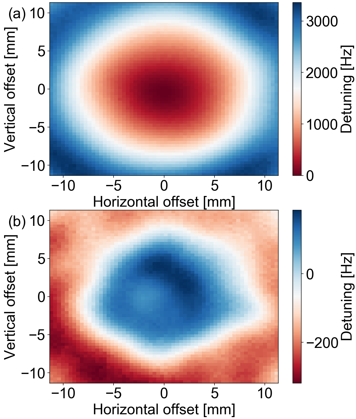
Similarly to the above, the wavefront error also has a dependence on beam size, which is different between the green and infrared beams as shown in Table. 1. A simulation was performed where different Gaussian weightings are required to evaluate how the mirror wavefront deviates from a perfect sphere. From this simulation, the results of which are shown in Fig. 2, we find a detuning variation of few kHz could happen. This is because a different RoC and averaged mirror height will be sensed by green and infrared beams after a cavity alignment change. More details of this simulation are provided in Supplement Material Note1 section five. However, due to the lack of the wavefront error measurements at 532 and 1064, the simulation is not completely accurate.
III.4 Residual amplitude modulation of sidebands
The Pound-Drever-Hall locking technique utilizes the beat signal between the carrier and phase modulated sidebands. However, the error signal has fluctuations due to residual amplitude modulation (RAM) that arises from various imperfections in the phase modulation process whittaker1985residual ; wong1985servo . In the past, RAM was found to produce noise in gravitational wave detectors kokeyama2014residual , and cause drift in the level of generated squeezing li2016reduction .
In this experiment, RAM is introduced at the green EOM, which causes a locking point error for the green beam and a corresponding detuning shift of infrared. In addition, RAM from the infrared EOM is present when bright alignment beam is used to characterise detuning.
IV Detuning drift sources identification
In this section, we report on the experimental identification of relative detuning sources of the filter cavity for green and infrared beams.
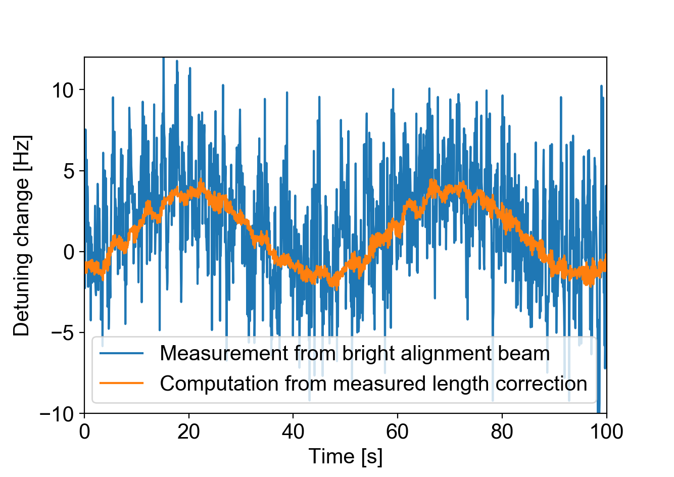
Testing detuning change with laser frequency.—In order to experimentally test Eq. 4, we introduce a sinusoidal main laser frequency shift and check detuning. The main laser frequency shift is introduced by changing the main laser crystal temperature. The control loop responses to the main laser frequency shift and corrects on the filter cavity end mirror position to keep the green beam locked on resonance. This correction signal is acquired and taken into Eq. 4 to obtain a detuning variation , which shows as the orange curve in Fig. 3. On the other hand, the filter cavity reflected bright alignment beam contains RF sidebands. A demodulation of this field at RF sideband frequency gives a PDH signal, which is calibrated in Hz as the blue curve in Fig. 3. These two curves in Fig. 3 match well, which proves that Eq. 4 describes well a detuning change caused by a length correction signal of the cavity length control loop.
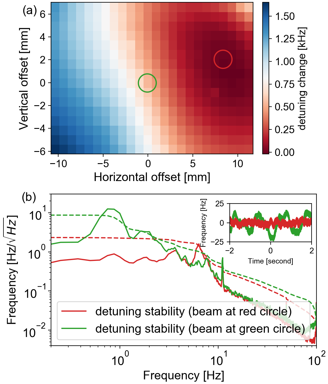
Testing detuning change with alignment.—Alignment-dependent detuning shift is measured by offsetting pointing control to scan a 1323 mm region on the filter cavity end mirror. At each position on the end mirror, we adjusted the AOM driving frequency to make the bright alignment beam resonant together with the green beam. By taking the AOM adjusted frequency relative to its nominal value, we get a resulting detuning shift mirror map as shown in Fig. 4 (a). A maximum detuning shift of 1.6 kHz was found. Similarly, we check detuning dependence on the input mirror beam position, where it was found that the spatial dependence of detuning was about 15 times less significant.
Fig. 4 (a) shows that intra-cavity beam jittering around the dark red region (indicated by a red circle) should introduce less detuning fluctuation compared to the mirror center (indicated by a green circle). This is because the beam angular motion coupling to length variation has a smaller gradient at the position indicated by the red circle in Fig. 4 (a). We moved the beam position from the green circle position to the red circle position on the end mirror, then measured the detuning spectrum from the bright alignment beam. It was seen that the RMS detuning stability was improved by a factor of 4, as shown in Fig. 4 (b).
Testing detuning change due to residual amplitude modulation—To measure the effect of RAM, we lock the filter cavity such that the bright alignment beam is anti-resonant. In this condition, the Pound-Drever-Hall error signal taken at the reflection of filter cavity is insensitive to phase change, and therefore only RAM can be seen in the error signal fluctuations around zero. We find that RAM can introduce detuning shift of around 4 Hz within a period of tens of minutes. In the future, we plan to use wedged crystal EOM to reduce RAM li2016reduction .
V Filter cavity detuning stabilization
After analyzing various detuning drift mechanisms, we find the most significant source is from the alignment drift and mirror jittering as shown in Fig. 4. We used alignment and pointing controls to keep the beam on the stable region of the end mirror, then measured long term detuning stability and frequency dependent squeezing.
Long term detuning stability was measured using the bright alignment beam while the filter cavity was locked with bichromatic controls for 16 hours. We obtained the filter cavity detuning change with the same method as used for Fig. 3, described in section IV. The measured detuning is shown by the blue curve in Fig. 5 (a) and is seen to have a variation of 8.05 Hz within 68% percentile. The inferred detuning change from the length correction and Eq. 4 is shown by the orange curve. In this plot, the overlap of blue and orange curves indicates that the detuning change mainly comes from the length correction signal caused by laser frequency drift, while their discrepancy is attributed to the RAM effect.
There are two re-locks in Fig. 5 (a) causing the cavity length and detuning jump. In the first re-lock, we noticed that it happened suddenly. Approximately 10 m displacement happened for the controlled mirror, which is a reasonable mirror motion within one pendulum period. But in the second re-lock, we left time for the mirror pendulum motion damping, which released an accumulated mirror displacement of approximately 30 m and made the detuning go back to zero. As calculated in section III.1 and observed in Fig. 5 (a), the detuning variation after cavity re-lock is only related to the cavity length change. Correspondingly, although a substantial laser frequency drift happened, it didn’t affect detuning after un-lock.
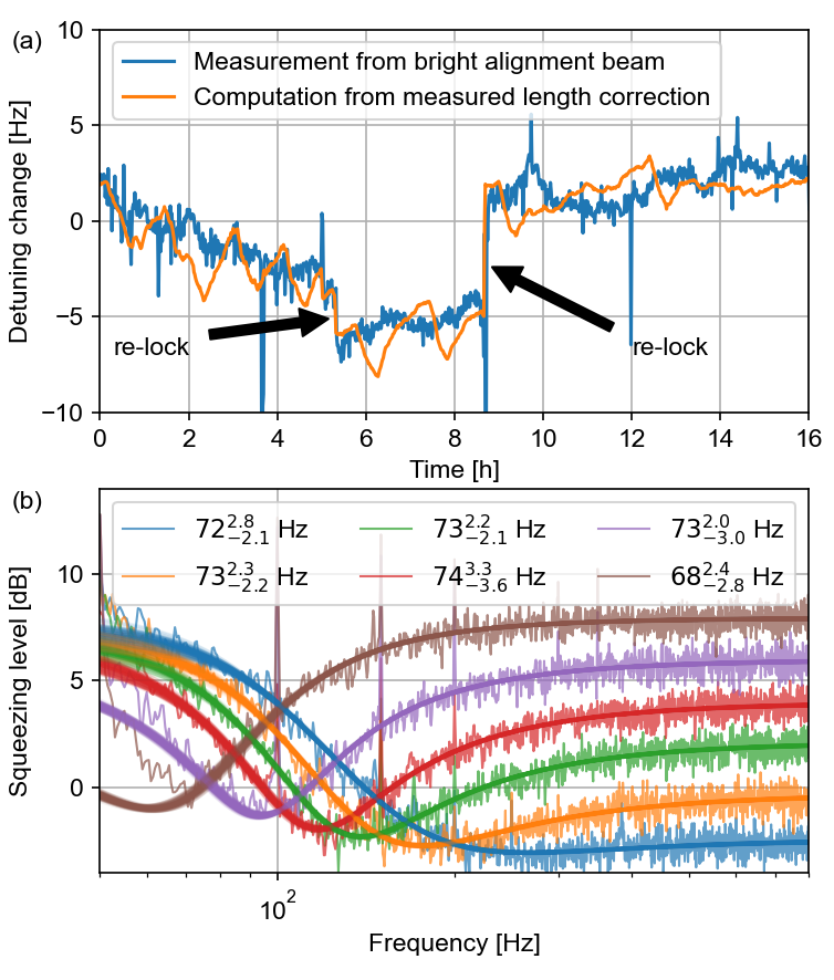
The detuning stability is also checked by characterizing frequency dependent squeezing as shown in Fig. 5 (b) using different homodyne angles. The whole measurement took one hour. We use the model of frequency dependent squeezing of Kwee et al. kwee2014decoherence to fit the measured data and extract the filter cavity detuning as one of the fit parameters, along with homodyne angle, propagation optical losses, and generated squeezing level. The fit is performed using ‘emcee’ foreman2013emcee , further details of which are provided in Supplemental Material Note1 section six. The fit results for six different homodyne angles are shown in the legend of Fig. 5 (b). A detuning fluctuation of is found by aggregating all fit results and checking the 68% percentile. The fluctuation of is slightly less than that measured over the course of 16 hours using the bright alignment beam.
VI Impact of improved filter cavity detuning stability on gravitational wave detection range
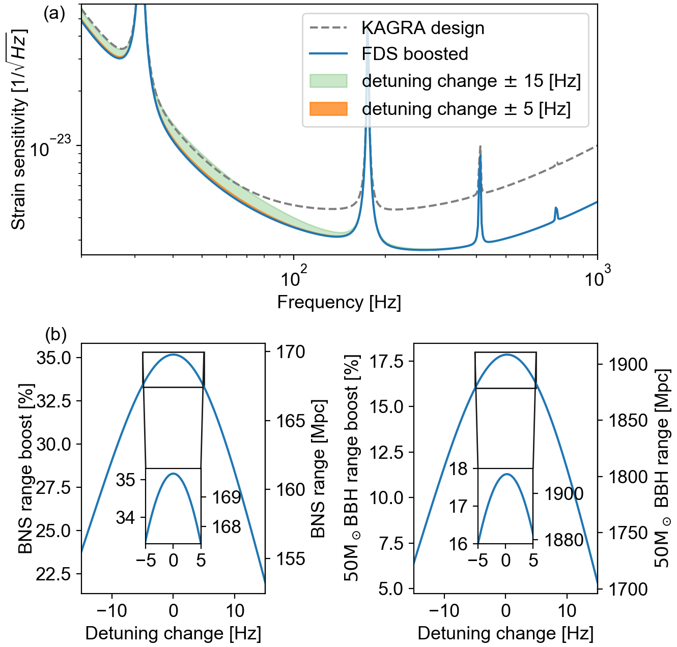
Frequency dependent squeezing requires the filter cavity to have a specific and stable detuning to optimize quantum noise reduction. To understand how the detuning drift impacts gravitational wave detector quantum noise, we make a simulation based on the frequency dependent squeezing model of Kwee et al. kwee2014decoherence and the noise budget of the KAGRA gravitational wave detector kagra_s . The result of frequency dependent squeezing with improved detuning stability in KAGRA is shown in Fig. 6. More details about this simulation are provided in Supplement Material Note1 section seven. Fig. 6 (a) shows that a detuning change of Hz can degrade the sensitivity such that there is no improvement from frequency dependent squeezing below 75 Hz. However, reducing the detuning drift to Hz makes the influence on detector sensitivity almost negligible. We characterize the improvement of KAGRA scientific output in terms of two relevant sources: 1)binary black hole (BBH) mergers of mass 50 as a representative of compact binary coalescences that occur at low frequency, 2) binary neutron star (BNS) detection. Their corresponding detection ranges are calculated using the inspiral-range package inspiral . This low frequency stabilization of detector sensitivity would benefit the early warning of binary neutron star mergers cannon2012 ; low2019 ; yu2021 ; chu2022 and the detection of intermediate-mass black holes mandel2008rates ; graff2015missing ; veitch2015measuring ; gw190521 . If filter cavity detuning stability is Hz, the introduction of frequency dependent squeezing increases the BNS range by 22.0% to 35.2%, while the 50 BBH range by 5.4% to 17.8%. The insets of Fig. 6 (b) show that by reducing the detuning drift to 5 Hz, the BNS range has a minimum boost of 33.4%, while the BBH range has a minimum boost of 16.0%. This corresponds to an overall range fluctuation reduction from 10.6% to 1.5%.
VII Conclusion and outlook
The stability of frequency dependent squeezed vacuum is crucial for reducing quantum noise in upcoming observing runs of gravitational wave detectors. We have developed bichromatic automatic filter cavity alignment and incident beam pointing controls for the infrared squeezed field using an overlapping harmonic green beam. We have investigated mechanisms that cause infrared detuning variation of the filter cavity, and found that the most significant contribution comes from alignment drift of the filter cavity mirrors combined with the beam position on the end mirror. The mirror jittering induced detuning fluctuation was reduced by positioning the intra-cavity beam at a stable region on the end mirror, reducing the RMS detuning fluctuation by a factor of four. After that, we have achieved frequency dependent squeezing with a detuning stability smaller than 10 Hz, an improvement of a factor of three from previously published results zhao2020frequency . Such FC detuning stability is crucial to fully take advantage of frequency dependent squeezing and avoid degrading the detector range.
Further improvements in the detuning stability will come from mitigating the large frequency shifts that occur in the length correction loop, for example, by using two AOMs or stabilizing main laser frequency. We should use wedged crystal EOMs to reduce residual amplitude modulation in Pound-Drever-Hall error signals. Although detuning drift caused by different mirror wavefront errors for green and infrared beams can be mitigated, their origin is not fully understood and should be further investigated.
For gravitational wave detectors, the squeezer laser is phase locked to the stable interferometer main laser, so we don’t expect detuning drift caused by laser frequency drift while the cavity is locked. Residual amplitude modulation induced detuning drift should be small since wedged crystal EOMs are usually employed in gravitational wave detectors. The filter cavity length change maybe an issue since ground motion and mirror suspension stability are different for different gravitational wave detectors, but this can be reduced by reducing green beam frequency shift using two AOMs.
The filter cavity intra-cavity optical losses has dependence on alignment isogai2013loss ; capocasa2018measurement , which can be investigated with bichromatic controls more precisely in the future.
There are also filter cavity control schemes that use infrared sidebands which are mode matched and co-propagating with the squeezed vacuum. These have been dubbed as the coherent control filter cavity scheme aritomi2020control ; aritomi2021 and resonant locking field scheme mcculler2020frequency . These schemes offer the advantage of ensuring a proper sensing of the filter cavity length noise for the squeezed vacuum. However, due to the configuration of the filter cavity compared to gravitational wave detectors, bichromatic control allows for comparatively easier lock acquisition and larger sensing power. If bichromatic controls are improved to the point where they can give close to ideal alignment of the squeezed field, then it will greatly ease the commissioning and lock acquisition of a gravitational wave detector using frequency dependent squeezing and provide faster improvement of scientific outcomes.
Acknowledgements
We thank J. Degallaix, X. Ding, and T. Liu for their contributions and discussions. We thank G. Hartmut and A. Jones for their comments on this work. We thank also Advanced Technology Center of NAOJ for the support. We acknowledge the help from members of KAGRA Collaboration, Virgo, and LIGO Collaboration. This work was supported by the JSPS Grant-in-Aid for Scientific Research (Grants No. 15H02095, No. 18H01235, and No. 21H04476), the JSPS Core-to-Core Program, and the EU Horizon 2020 Research and Innovation Programme under the Marie Sklodowska-Curie Grant Agreement No. 734303. Y. Z. was supported by the Graduate University of Advanced Studies, SOKENDAI, by the Japanese government MEXT scholarship, and by the ICRR Young Researcher’s Fund. M. E. was supported by the JSPS Standard Postdoctoral Fellowship (20F20803). M. P. was supported by the JSPS Standard Postdoctoral Fellowship (20F20713). H. L. and H. V. were supported by the Deutsche Forschungsgemeinschaft (DFG, German Research Foundation) under Germany’s Excellence Strategy - EXC 2123 QuantumFrontiers - 390837967. N. A. was supported by JSPS Grant-in-Aid for Scientific Research (Grant No. 18H01224), JSPS Grant-in-Aid for Challenging Research (Exploratory) (Grant No. 18K18763), and JST CREST (Grant No. JPMJCR1873).
References
- (1) LIGO Scientific Collaboration, J. Aasi et al., “Advanced LIGO”, Class. Quantum Grav. 32 no. 7, (2015) 074001.
- (2) The Virgo Collaboration, F. Acernese et al., “Advanced Virgo: a second-generation interferometric gravitational wave detector”, Class. Quantum Grav. 32 no. 2, (2015) 024001.
- (3) The KAGRA Collaboration, Y. Aso, Y. Michimura, K. Somiya, M. Ando, O. Miyakawa, T. Sekiguchi, D. Tatsumi, and H. Yamamoto, “Interferometer design of the KAGRA gravitational wave detector”, Phys. Rev. D 88 (Aug, 2013) 043007.
- (4) The Virgo Collaboration, F. Acernese, M. Agathos, L. Aiello et al., “Increasing the astrophysical reach of the advanced Virgo detector via the application of squeezed vacuum states of light”, Phys. Rev. Lett. 123 (Dec, 2019) 231108.
- (5) LIGO Scientific Collaboration, M. Tse, H. Yu, N. Kijbunchoo et al., “Quantum-Enhanced Advanced LIGO Detectors in the Era of Gravitational-Wave Astronomy”, Phys. Rev. Lett. 123 (Dec, 2019) 231107.
- (6) LIGO Scientific Collaboration, A. Buikema et al., “Sensitivity and performance of the Advanced LIGO detectors in the third observing run”, Phys. Rev. D 102, (Sep, 2020) 062003.
- (7) The Virgo Collaboration, F. Acernese, M. Agathos, L. Aiello et al., “Quantum backaction on kg-scale mirrors: Observation of radiation pressure noise in the Advanced Virgo detector”, Phys. Rev. Lett. 125 (Sep, 2020) 131101.
- (8) H. Yu, L. McCuller, M. Tse et al., “Quantum correlations between light and the kilogram-mass mirrors of LIGO”, Nature 583 (2020) 43-47.
- (9) H. J. Kimble, Y. Levin, A. B. Matsko, K. S. Thorne, and S. P. Vyatchanin, “Conversion of conventional gravitational-wave interferometers into quantum nondemolition interferometers by modifying their input and/or output optics”, Phys. Rev. D 65 (Dec, 2001) 022002.
- (10) P. Purdue, Y. Chen, “Practical speed meter designs for quantum nondemolition gravitational-wave interferometers”, Phys. Rev. D 66 (Dec, 2002) 122004.
- (11) F. Y. Khalili, “Optimal configurations of filter cavity in future gravitational-wave detectors”, Phys. Rev. D 81 (Jun, 2010) 122002.
- (12) M. Evans, L. Barsotti, P. Kwee, J. Harms, and H. Miao, “Realistic filter cavities for advanced gravitational wave detectors”, Phys. Rev. D 88 (Jul, 2013) 022002.
- (13) P. Kwee, J. Miller, T. Isogai, L. Barsotti, and M. Evans, “Realistic filter cavities for advanced gravitational wave detectors”, Phys. Rev. D 90 (Sep, 2014) 062006.
- (14) Y. Zhao, N. Aritomi, E. Capocasa, M. Leonardi, M. Eisenmann, Y. Guo, E. Polini, A. Tomura, K. Arai, Y. Aso, Y. C. Huang, R. K. Lee, H. Lück, O. Miyakawa, P. Prat, A. Shoda, M. Tacca, R. Takahashi, H. Vahlbruch, M. Vardaro, C. M. Wu, M. Barsuglia, and R. Flaminio, “Frequency-Dependent Squeezed Vacuum Source for Broadband Quantum Noise Reduction in Advanced Gravitational-Wave Detectors”, Phys. Rev. Lett. 124 (Apr, 2020) 171101.
- (15) L. McCuller, C. Whittle, D. Ganapathy, K. Komori, M. Tse, A. Fernandez-Galiana, L. Barsotti, P. Fritschel, M. MacInnis, F. Matichard, K. Mason, N. Mavalvala, R. Mittleman, Haocun Yu, M. E. Zucker, and M. Evans, “Frequency-Dependent Squeezing for Advanced LIGO”, Phys. Rev. Lett. 124 (Apr, 2020) 171102.
- (16) R. Flaminio, “Status and plans of the Virgo gravitational wave detector”, Proc. SPIE 11445 (Dec, 2020) 1144511.
- (17) L. Barsotti, L. McCuller, M. Evans, P. Fritschel, “The A+ design curve”, LIGO Document T1800042 (Dec, 2018).
- (18) Y. Michimura, K. Komori, Y. Enomoto, K. Nagano, A. Nishizawa, E. Hirose, M. Leonardi, E. Capocasa, N. Aritomi, Y. Zhao, R. Flaminio, T. Ushiba, T. Yamada, L. W. Wei, H. Takeda, S. Tanioka, M. Ando, K. Yamamoto, K. Hayama, S. Haino, and K. Somiya, “Prospects for improving the sensitivity of the cryogenic gravitational wave detector KAGRA”, Phys. Rev. D 102 (Jul, 2020) 022008.
- (19) E. Oelker, T. Isogai, J. Miller, M. Tse, L. Barsotti, N. Mavalvala, and M. Evans, “Audio-Band Frequency-Dependent Squeezing for Gravitational-Wave Detectors”, Phys. Rev. Lett. 116 (Jan, 2016) 041102.
- (20) H. Vahlbruch, M. Mehmet, K. Danzmann, and R. Schnabel, “Detection of 15 dB Squeezed States of Light and their Application for the Absolute Calibration of Photoelectric Quantum Efficiency”, Phys. Rev. Lett. 117 (Sep, 2016) 110801.
- (21) M. Stefszky et al., “An investigation of doubly-resonant optical parametric oscillators and nonlinear crystals for squeezing”, J. Phys. B: At. Mol. Opt. Phys. 44 (2010) 015502.
- (22) The KAGRA Collaboration, T. Akutsu et al., “An arm length stabilization system for KAGRA and future gravitational-wave detectors”, Class. Quantum Grav. 37 no. 3, (2020) 035004.
- (23) N. Aritomi, M. Leonardi, E. Capocasa, Y. Zhao, R. Flaminio, “Control of a filter cavity with coherent control sidebands”, Phys. Rev. D 102 (Aug, 2020) 042003.
- (24) E. D. Black, “An introduction to Pound–Drever–Hall laser frequency stabilization”, American Journal of Physics 69 no. 1, (2001) 79–87.
- (25) See Supplement Material at (there will be a link provided by PRD), which includes Ref. diaz2018control ; heinzel1999automatic ; freise2010interferometer ; anderson1984alignment ; canuel2014sub ; galvo ; sassolas2018high ; kwee2014decoherence ; foreman2013emcee ; whittle2020optimal
- (26) L. Barsotti, “The control of the Virgo interferometer for gravitational wave detection”, Ph. D. thesis, Pisa University (2006).
- (27) A. Araya, A. Takamori, A. Morii et al., “Design and operation of a 1500-m laser strainmeter installed at an underground site in Kamioka, Japan”, Earth Planets Space 69 (2017) 77.
- (28) T. Sagiya “A decade of GEONET: 1994–2003 —The continuous GPS observation in Japan and its impact on earthquake studies”, Earth Planets Space 56 (2004) xxix–xli.
- (29) P. Kwee, C. Bogan, K. Danzmann et al., “Stabilized high-power laser system for the gravitational wave detector advanced LIGO”, Opt. Express 20 (2012) 10617-10634.
- (30) M. Vardaro, “Frequency stability of DDS based RF distribution for AdV+ QNR system”, in preparation (2021).
- (31) M. Evans, S. Ballmer, M. Fejer, P. Fritschel, G. Harry, G. Ogin, “Thermo-optic noise in coated mirrors for high-precision optical measurements”, Phys. Rev. D 78 (Nov, 2008) 102003.
- (32) W. Yam, S. Gras, M. Evans, “Multimaterial coatings with reduced thermal noise”, Phys. Rev. D 91 (Feb, 2015) 042002.
- (33) M. Eisenmann, “Use of squeezed vacuum states to reduce the quantum noise of the Advanced Virgo gravitational wave detector”, Ph. D. thesis, Savoy Mont Blanc University (2020).
- (34) B. Sassolas, M. Betoule, N. Regnault et al., “High precision metrology for large bandpass filters”, Proc. SPIE 10706 (July, 2018) 107064E.
- (35) E. Capocasa, M. Barsuglia, J. Degallaix, L. Pinard, N. Straniero, R. Schnabel, K. Somiya, Y. Aso, D. Tatsumi, and R. Flaminio, “Estimation of losses in a 300 m filter cavity and quantum noise reduction in the KAGRA gravitational-wave detector”, Phys. Rev. D 93 (Apr, 2016) 082004.
- (36) E. A. Whittaker, M. Gehrtz, G. C. Bjorklund, “Residual amplitude modulation in laser electro-optic phase modulation”, J. Opt. Soc. Am. B 2 (1985) 1320-1326.
- (37) N. C. Wong, J. L. Hall, “Servo control of amplitude modulation in frequency-modulation spectroscopy: demonstration of shot-noise-limited detection”, J. Opt. Soc. Am. B 2 (1985) 1527-1533.
- (38) K. Kokeyama, K. Izumi, W. Z. Korth et al., “Residual amplitude modulation in interferometric gravitational wave detectors”, J. Opt. Soc. Am. B 31 (2014) 81-88.
- (39) Z. Li, W. Ma, W. Yang et al., “Reduction of zero baseline drift of the Pound–Drever–Hall error signal with a wedged electro-optical crystal for squeezed state generation”, Opt. Lett. 41 (2016) 3331-3334.
- (40) D. F. Mackey et al., “emcee: The MCMC Hammer”, PASP 125 (2013) 306.
- (41) Y. Enomoto, K. Komori, Y. Michimura et al., “Target sensitivity of bKAGRA”, JGW T1707038 (Aug, 2017).
- (42) J. Rollins, J. Creighton, “GW detector inspiral range calculation tools”, (2017).
- (43) T. Isogai, J. Miller, P. Kwee et al., “Loss in long-storage-time optical cavities”, Opt. Express 21 (2013) 30114-30125.
- (44) E. Capocasa, Y. Guo, M. Eisenmann, Y. Zhao, A. Tomura, K. Arai, Y. Aso, M. Marchiò, L. Pinard, P. Prat, K. Somiya, R. Schnabel, M. Tacca, R. Takahashi, D. Tatsumi, M. Leonardi, M. Barsuglia, and R. Flaminio, “Measurement of optical losses in a high-finesse 300 m filter cavity for broadband quantum noise reduction in gravitational-wave detectors”, Phys. Rev. D 98 (Jul, 2018) 022010.
- (45) N. Aritomi, “Demonstration of length control for a filter cavity with coherent control sidebands”, in preparation (2021).
- (46) K. Cannon, R. Cariou, A. Chapman et al., “Toward early-warning detection of gravitational waves from compact binary coalescence”, ApJ 748 (2012) 136.
- (47) B. P. Abbott, R. Abbott, T. D. Abbott et al., “Low-latency gravitational-wave alerts for multimessenger astronomy during the second Advanced LIGO and Virgo observing run”, ApJ 875 (2019) 161.
- (48) H. Yu, R. X. Adhikari, R. Magee, S. Sachdev, and Y. Chen, “Early warning of coalescing neutron-star and neutron-star-black-hole binaries from the nonstationary noise background using neural networks”, Phys. Rev. D 104 (2021) 062004.
- (49) Q. Chu, M. Kovalam, L. Wen, S. Sachdev, and Y. Chen, “SPIIR online coherent pipeline to search for gravitational waves from compact binary coalescences”, Phys. Rev. D 105 (2022) 024023.
- (50) I. Mandel, D. A Brown, J. R. Gair, and M. C. Miller, “Rates and characteristics of intermediate mass ratio inspirals detectable by Advanced LIGO”, ApJ 681 (2008) 1431.
- (51) P. B. Graff, A. Buonanno, and B. S. Sathyaprakash, “Missing Link: Bayesian detection and measurement of intermediate-mass black-hole binaries”, Phys. Rev. D 92 (2015) 022002.
- (52) J. Veitch, M. Pürrer, and I. Mandel, “Measuring Intermediate-Mass Black-Hole Binaries with Advanced Gravitational Wave Detectors”, Phys. Rev. Lett. 115 (2015) 141101.
- (53) LIGO Scientific Collaboration, The Virgo Collaboration, “GW190521: A Binary Black Hole Merger with a Total Mass of ”, Phys. Rev. Lett. 125 (2020) 101102.
- (54) J. C. Diaz, J. Creighton, “Control of the gravitational wave interferometric detector Advanced Virgo”, Springer (2018).
- (55) G. Heinzel, A. Rüdiger, R. Schilling, K. Strain, W. Winkler, J. Mizuno, K. Danzmann, “Automatic beam alignment in the Garching 30-m prototype of a laser-interferometric gravitational wave detector”, Optics Communications 160 (1999) 321-334.
- (56) A. Freise, K. Strain, “Interferometer techniques for gravitational-wave detection”, Living Reviews in Relativity 13 (2010) 1-81.
- (57) D. Z. Anderson, “Alignment of resonant optical cavities”, Appl. Opt. 23 (1984) 2944-2949.
- (58) B. Canuel, E. Genin, M. Mantovani, J. Marque, P. Ruggi, and M. Tacca, “Sub-nanoradiant beam pointing monitoring and stabilization system for controlling input beam jitter in gravitational wave interferometers”, Appl. Opt. 53 (2014) 2906-2916.
- (59) G. Heinzel, “TAMA beam centering system”, (1999).
- (60) C. Whittle, K. Komori, D. Ganapathy, L. McCuller, L. Barsotti, N. Mavalvala, and M. Evans, “Optimal detuning for quantum filter cavities”, Phys. Rev. D 102 (Nov, 2020) 102002.