A Walking Space Robot for On-Orbit Satellite Servicing: The ReCoBot
Abstract
A key factor in the economic efficiency of satellites is their availability in orbit. Replacing standardized building blocks, such as empty fuel tanks or outdated electronic modules, could greatly extend the satellites’ lifetime. This, however, requires flexible robots that can locomote on the surface of these satellites for optimal accessibility and manipulation. This paper introduces ReCoBot, a 7-axis walking space manipulator for locomotion and manipulation. The robot can connect to compatible structures with its symmetric ends and provides interfaces for manual teleoperation and motion planning with a constantly changing base and tip. We build on open-source robotics software and easily available components to evaluate the overall concept with an early stage demonstrator. The proposed manipulator has a length of 1.20 m and a weight of 10.4 kg and successfully locomotes over a satellite mockup in our lab environment.
I Introduction
Thousands of satellites orbit the earth for communication and observation and build the basis for key technologies of our modern life. Despite functioning electronics, however, satellite lifetime often ends when running out of fuel. And unforeseen events, such as damage through space debris, pose an additional threat to their reliability. The on-orbit servicing of satellites could partly compensate for those failures [1],[2], but requires new concepts for satellite design and robotic servicers. Fully modular approaches with box-shaped components [3], could simplify and reduce the on-orbit maintenance of spacecraft to the exchange of individual modules. Building on a common interface for mechanical coupling and data exchange [4], the challenge is to develop robotic manipulators that can dynamically reposition themselves on these spacecraft for on-orbit maintenance.
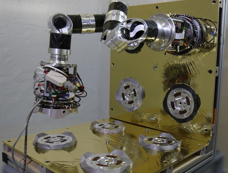
This paper presents ReCoBot, a seven-axis, walking manipulator for the reconfiguration of satellite components. Both of the robot’s ends are equipped with the iSSI-interface [4], such that locomotion on compatible satellites is possible via dynamic changes of base and tip of the kinematic chain. Following some concepts of new space [5], we build ReCoBot with consumer electronics, light-weight robotic motors, and community-driven, open-source software. This gives us the advantage of developing and realizing the concept in a short time and obtaining early insights into the overall concept. We address the challenges of designing such a robot both for space and for earth’s gravity. Although not required during its envisioned operation on-orbit, the components need to sustain increased loads in earth’s gravity for testing. Furthermore, we build ReCoBot’s software on the Robot Operating System (ROS) [6], which provides a rich set of tools and algorithms for robotics, and we describe the adaptation needed for motion planning to realize our use case of caterpillar-like movement. Fig. 1 shows ReCoBot in action. Our proposed system has a length of , weighs and can hold itself on vertical iSSI interfaces for locomotion. With few further modifications, the design will be ready for a zero-gravity environment.
The structure of this paper is as follows: Section II discusses related works with similar ideas and differences to our system, and Section III briefly summarizes our high-level goals for the next sections. Section IV then presents the hardware design, followed by electronics in Section V and software in Section VI. Evaluation results are presented in Section VII before we conclude the paper with perspectives on future work in Section VIII.
II Related Work
In the concept of on-orbit servicing, the manipulators are usually co-developed with a common standard for the connection of satellite modules. In addition to the iSSI interface on which we build in this paper, there are further alternatives currently developed with similar purposes and characteristics. Aligned with the iSSI, they comprise several functions in one multi-purpose interface to meet the needs of future space applications, such as mechanical coupling of components, power, fluid transfer, or data exchange [7],[8]. These interfaces are then envisioned to connect manipulators for operating on the surfaces of satellites. Recent manipulators include the MOSAR-WM [9] system and its successor MAR [10]. This concept equips a seven-axis robotic manipulator with two HOTDOCK [8] interfaces and describes a possible use case with the construction of mirror arrays in orbit. Sharing the principal motivation behind these designs, we seek to develop a manipulator compatible with the iSSI interface.
A basic three-axis system was recently developed for the iSSI [11] but is strongly limited in its capabilities to manipulate within all six Cartesian dimensions of its end-effector. In contrast, the seven-axis of our proposed manipulator enable such manipulation and locomotion over distributed iSSI interfaces on the surface of a compatible satellite.
The software needed to control such devices is only partially covered with frameworks for space robotics applications, such as [12]. The complexities of manipulation and locomotion shift the focus towards algorithms from the field of robotics, such as motion planning. It is thus of interest to evaluate open-source robotics middlewares, such as ROS [6], with our use case of a locomoting manipulator.
III ReCoBot - Vision and Application
The concept of ReCobot is embedded into the bigger picture of infrastructure for on-orbit satellite servicing. For such a maintenance mission, we assume that a ReCoBot-like system is deployed on a client satellite. We further assume that this client satellite is composed of suitable building blocks that are interconnected by the intelligent Space System Interface (iSSI) [3] [4]. To successfully perform maintenance operations, individual blocks need to be exchanged by the robot in place.
The goal of this paper is to contribute a pragmatic, testable design for such a system and to think through the required methods from a robotics point of view.
IV Hardware Design
ReCoBot is comprised of eight segments that are connected by seven revolute joints. The compatibility with the iSSI interfaces and the goal to locomote over satellites with such block structures determine the approximate lengths of the segments. With this setup, the robot could reach most targets within its workspace in initial analyses. Special emphasis was placed on a lightweight construction during the development to ensure a functioning prototype under earth’s gravity conditions. The main materials used were aluminum alloys and carbon tubes to withstand the forces and torques under gravity. A quasi-static estimation of reaction forces and torques in each joint was carried out using algorithms from the Kinematics and Dynamics Library (KDL)111http://wiki.ros.org/orocos_kinematics_dynamics in ROS.
The current ReCoBot has a maximum reach of and a total mass of .
IV-A Components
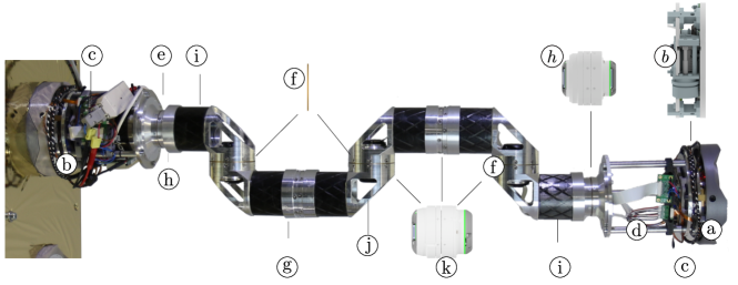
Fig. 2 shows an overview of the complete system with details in CAD. In the following, we list and describe the main components of the ReCoBot setup.
-
(a)
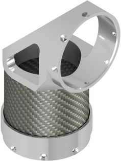
Form fits at both ends of ReCoBot provide inserting chamfers for the docking process with other satellite modules. They shall improve the overall mechanical stability and reduce mechanical stress of the iSSI when docked.
-
(b)
The integrated iSSI interface as described in Section III.
-
(c)
(d) (g) (i) Structural components and adapters. The TCP housing was originally designed as a closed structure, but was then expanded to an open, more flexible structure with three Aluminum alloy rods. It accommodates the Kinova controller on one side and leaves enough space for a battery pack on the other end of ReCoBot. Additional adapters, such as the mount for the main on-board CPU and the iSSI are placed inside the TCP housing and are partly attached to the rods.
-
(e)
Adapter for small actuators.
-
(f)
Copper alloy bushings between the flanges reduce friction and absorb bending moments. They also increase the system’s overall stiffness through reducing flex in the joints and thus mitigate uncertainty in the robot’s kinematics.
-
(h)
(k) Kinova actuators.
-
(i)
CFRP tube-shaped link segments provide structural stiffness with low weight. They are glued to the actuator housings.
-
(j)
Elbow actuator housings are attached to the motors with screws for easy maintenance.
IV-B Actuators
We use second-generation KA-Series Kinova geared motors in ReCoBot. Two KA-58 actuators (h) are integrated in the wrist joints, while the remaining joints are driven by five KA-75+ actuators (k). The KA-Series actuators consist of two disk-shaped parts, each fixed to the flange of the robotic segments, respectively. Inside the motors, a slip ring allows for a continuous rotation[13], which supports to lay the connecting 20 pins flat flex cable inside the segments. The geared motors feature a torque sensor as well as an absolute position encoder.
IV-C Optimization
To meet the requirements of the maximum payloads of the actuators on earth, the elbow actuator housing (j) was subject to a series of improvements.
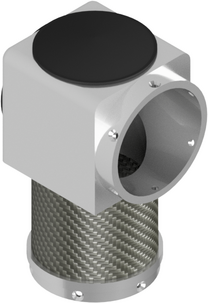
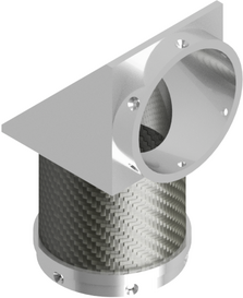
We used a topology optimization approach to remove excess material under low stress and evaluated the optimized design using FEM analysis. Fig. 3 shows selected steps of this refinement. The starting point was the housing of Fig. 3(a) as a baseline. Fig. 3(b) shows an improved version, and Fig. 3(c) shows the final design that was created with CAD-based topology optimization. Further improvements would be possible. Available manufacturing methods, however, are a limiting factor in design optimization.
V Electronics and Integration
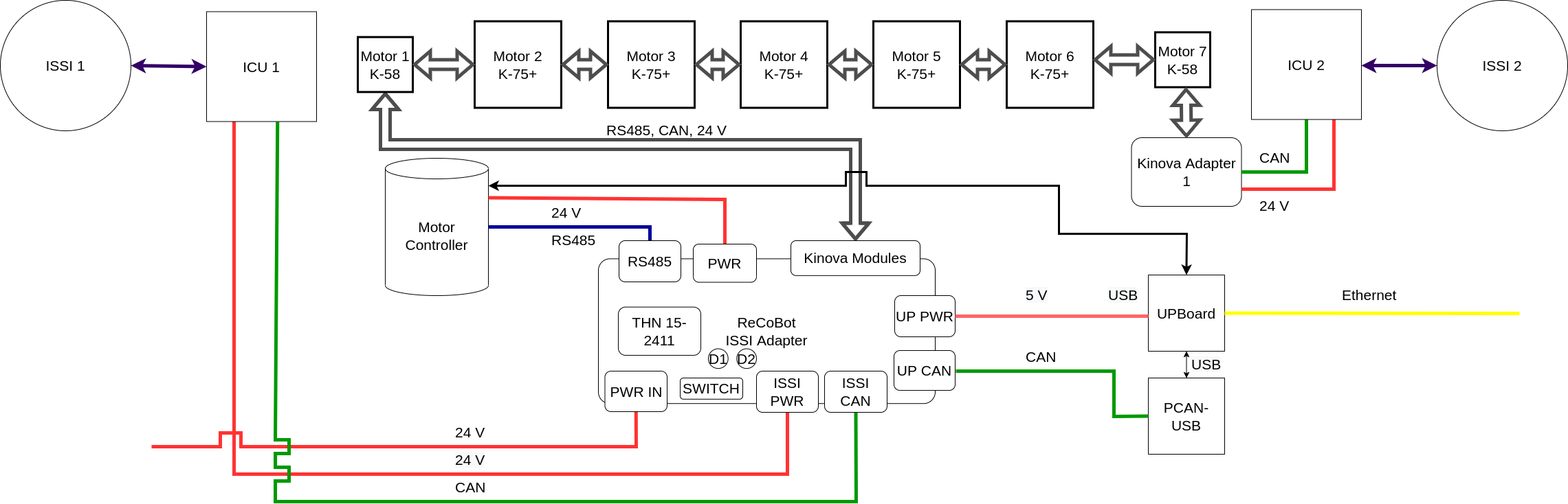
One objective of the design process was to lay the cables inside the segments along the arm to best support ReCoBot’s movements. We further designed ReCoBot to have all critical components, like the motor controller, the computing unit, network interfaces for Ethernet and USB, and power switches easily accessible in the open TCP housing. Figure 4 shows a schematic overview of ReCoBot’s electrical components and connections.
Most of ReCoBot’s electrical architecture is based on , which is currently supplied by an external source. Our concept envisions integrated batteries for this task at a later stage. The iSSI interfaces, its corresponding Interface Control Unit (ICU), as well as the motor controller, and the KA-series actuators are operated with this voltage. An additional DC/DC converter on the adapter provides for a compact 04/64 UP board that serves as a single-board computer for all of ReCoBot’s software applications and control. It runs an Ubuntu 20.04 LTS 64-bit OS with an x86 processor architecture. The UP board has a small mechanical footprint while providing a performant platform for running the necessary software applications.
The FZI ReCoBot iSSI adapter serves as the main distribution board of the architecture. It connects to the UP board, the motor controller, the KA-series actuators, as well as the ICU boards. It provides interfaces to the power supply and the two data buses, RS485 and CAN. The main communication line is a 20 pin flex cable, which daisy chains the components along the robotic arm in sequential order. Table I shows the respective pin assignment.
| Pin # | Signal |
|---|---|
| 1 - 8 | 24 V |
| 9 - 16 | GND |
| 17 / 18 | RS485 low / high |
| 19 / 20 | CAN low / high |
The Kinova actuators use the RS485 specification for communication with a dedicated input and output connector when daisy-chaining. The FZI ReCoBot iSSI adapter additionally splits off a CAN signal and for controlling the iSSI interface. We use a PCAN adapter for this task in combination with the UP board. Each iSSI has an integrated ICU unit.
VI Software and Control
ReCoBot’s software combines available open-source libraries and custom implementations within the ROS framework [6]. The high-level goals of the software are the actuation of all electronic components and control of the robot’s joints; collision-free motion planning to Cartesian target poses and joint configurations; the locomotion over satellite structures with the iSSI standard; and a basic interface for teleoperation and manipulation.
A special focus is the motion planning component. Although being established in academia and industry, Moveit [14] requires some particular tweaks to support our use case of locomotion, i.e. motion planning with a kinematic chain whose basis and tip change their connection frequently with the environment. The next sections highlight the important components and details.
VI-A iSSI end-effectors
The iSSI end-effectors are controlled through a custom CAN-bus driver, which encapsulates the interface with a state machine for docking ReCoBot to its environment. In addition to opening and closing the mechanical clutches, the driver offers continuous monitoring of internal parameters, such as supply voltage and the temperature of critical components. Additionally, integrated hall sensors and end stops allow for verification of the coupled connection.
VI-B Joint control and actuation
Kinova’s motors come with a dedicated SDK and a high-level API. During the development for this research, however, this SDK was not compatible with our configuration of seven Kinova motors. We, therefore, build ReCoBot’s actuation on a custom RS-485-based driver, which handles the communication through the Kinova motor controller. Our driver implements a hardware abstraction layer for and a ROS-control[15] based hardware interface. This enables position control at with feedback about motor positions, velocities, and a rough estimation of applied joint torques.
VI-C Motion planning for locomotion
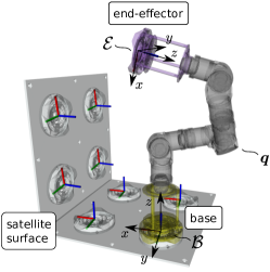
ReCoBot can use its iSSIs of both ends to dock itself to satellite surfaces. Opening and closing them dynamically allows for step-wise locomotion, and grasping and moving individual satellite blocks can be done similarly. We use the Moveit framework [14] for collision-free motion planning. Our envisioned use case of on-orbit manipulation assumes a structured environment with static collision objects. Fig. 5 shows ReCoBot on the surface of an exemplary satellite in simulation. The frames in the robot’s base and end-effector are oriented in such a way that they coincide with the satellite’s iSSIs when docked. All iSSIs represent possible target poses on the satellite’s surface. We further differentiate three states for ReCoBot’s configuration during locomotion:
-
•
Regular docked: The connection is closed via
-
•
Inverted docked: The connection is closed via
-
•
In transition: Both ends are docked
Although both of ReCoBot’s ends are equally capable end-effectors for manipulation, we draw this distinction here to avoid confusion in succeeding explanations.
Having a calibrated model of the satellite and the robot, locomotion is realized through a repetitive sequence of dynamically opening and closing iSSI connections and moving either base or tip. This simplification allows us to use established planning algorithms. Algorithm 1 shows the high-level steps.
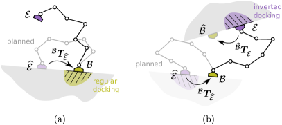
Steps and apply a trick to comply with the Moveit framework: We take the robot’s base as the planning reference frame during locomotion for both the regular and inverted docking scenarios and instead perform a dynamic update to the robot’s kinematics representation. This allows us to use a single planning instance and smoothly transition between both docking cases. Since we cannot change the given order of links and joints, we instead need to re-attach the environment properly. Fig. 6 illustrates both cases that we briefly describe in the following.
VI-C1 Regular docking
The robot kinematics is attached to the environment via its base and the planned goal pose of the end-effector is given with . Its coordinates are determined by the transformation that transforms from goal coordinates to the planning reference. Fig. 6(a) shows an exemplary planning result. After trajectory execution, the robot’s end-effector coincides with the planned goal pose .
VI-C2 Inverted docking
The environment is attached to the robot’s kinematics via the end-effector . Fig. 6(b) illustrates an exemplary planning goal for the robot’s base. We obtain the coordinates from the transformation , which is equivalent to describing the end-effector goal after the planned execution with respect to the robot’s planning reference . After trajectory execution, the robot’s end-effector has moved the environment in such a way that the robot’s base coincides with the planned goal .
We obtain all transformations as lookups from our calibrated environment that incorporates real-time feedback via forward kinematics from ReCoBot’s joint states. During locomotion, each planning result is a smooth trajectory with a user-defined duration that is executed with the joint trajectory controller.
VI-D Cartesian control and teleoperation
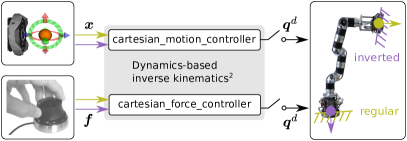
Collision-free motion planning covers broad workspace motions with arbitrary configuration changes. The goal of the additional, manual control interfaces is to offer an intuitive alternative for fine-grained manipulation in a relatively small volume. Offering a suitable trade-off between simplicity and intuitiveness, it is assumed that no configuration changes and no self-collision checking are necessary in this case. Fig. 7 shows an overview.
The two controller types cartesian_motion_controller and cartesian_force_controller are used from our control suite222https://github.com/fzi-forschungszentrum-informatik/cartesian_controllers. They turn task space inputs into position commands for the seven joints. Two separate instances of each controller can be used to steer the tip of the kinematic chain in the regular and inverted docking case, respectively.
Both controllers share a common solver for the inverse kinematics problem that computes joint position commands with a dynamics-based approach. In short, this solver turns user input into a virtual, goal-directed vector that drives a virtual model of the robot in that direction. The simulated reaction of the system is then streamed as desired reference to the joint position controllers of the real robot. A feature of the solver is a good trade-off between task space linearity and singularity robustness through conditioning the virtual operational space inertia of the system. We refer the interested reader to [16] and [17] for more details on this concept.
The Cartesian control supports two input modalities to steer ReCoBot: The first one is a virtual 6D handle in our visualization environment that formulates the end-effector’s target pose (position and rotation quaternion) with respect to the base frame of the current docking. Its strength is precise control in individual axes. The second input modality is more intuitive for steering several Cartesian axes at the same time. We use a 3DConnexion spacemouse as a joystick which offers to measure displacements in all six Cartesian axes. The data are adequately scaled according to the desired manipulation sensitivity and then passed to the cartesian_force_controller in form of a force-torque vector . The term force control, however, needs a brief explanation: Reaction forces with the environment are currently not actively controlled and is purely used for steering the robot. This is due to the quality of measured joint torques being currently insufficient for Cartesian closed-loop control. Interaction with the environment must thus be anticipated by the operator, which can be realized through observing the rendering of real-time joint feedback for instance. A minimal amount of compliance for slow motion in contact is provided by the structural mechanics.
VII Evaluation and Results
We tested ReCoBot’s core functionalities both in a basic simulator and on a specially designed mockup in a lab environment. The simulator has the advantage of providing an idealized behavior for an in-depth analysis of the used algorithms, and was used for evaluating the locomotion concept individually. In addition, the lab environment allows for evaluating ReCoBot’s hardware and electronics concept within focussed use cases. The next sections provide an excerpt of two examples with highlights.
VII-A Software and Locomotion
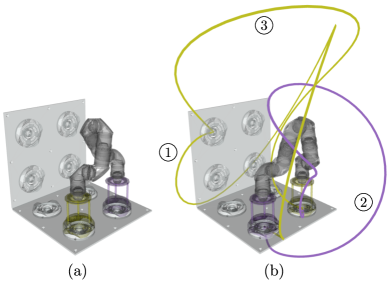
The basic simulation environment consisted of a kinematics representation of ReCoBot, docked to the surface dummy of an exemplary satellite. Dynamic phenomena were neglected and the robot’s joint control simply reported back the commanded positions as current states. The motion planning component had a sufficiently exact knowledge of the robot and its environment in form of approximated collision meshes from CAD data. The robot started in a transition phase, as depicted in Fig. 8(a), and the goal was to switch base and end-effector in place.
Fig. 8(b) shows the resulting locomotion in form of traveled end-effector paths. The endpoint traces were computed based on forward joint position kinematics and the colors correspond to the regular and inverted docking case from Section VI. In this example, the robot had to utilize a user-specified interface on the top left corner to relocate its base. The numbers next to the recorded paths show the order of execution. We used the RRT∗ algorithm [18] for these experiments, which found quick initial solutions and used the given planning time of per movement for further optimization of path costs.
We found through the experiments that most target poses where reachable within the given grid of iSSIs. We noted, however, that the high mesh accuracy of the form fits negatively influenced the success rate of the planners due to recognized collisions in the robot’s start and end states, which could be circumvented with a specific adaptation of collision meshes for motion planning.
VII-B System Tests in the Lab Environment
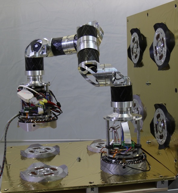
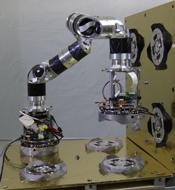
The mockup consisted of two rectangular-oriented walls with eight iSSIs arranged in a grid. Similar to the simulation environment, the iSSI centers were arranged apart.
We tested ReCoBot and the interplay of all components in different docking scenarios. The joints and iSSI end-effectors were actuated by the integrated onboard PC and the robot published real-time feedback over LAN for further processing. The iSSI interfaces of the dummy satellite were not actuated and provided the passive counterpart for the active bayonet clutch of the robot’s ends. The opening and closing of the end-effector iSSIs for docking were triggered by user commands. For these experiments, we powered the robot through an external cable.
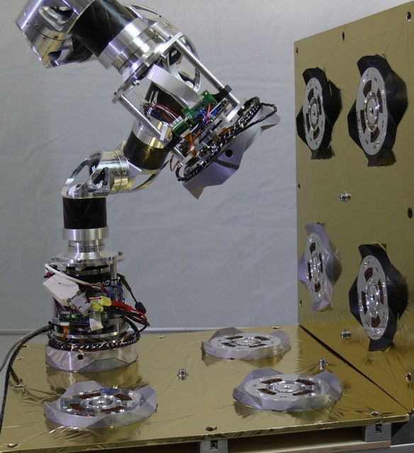
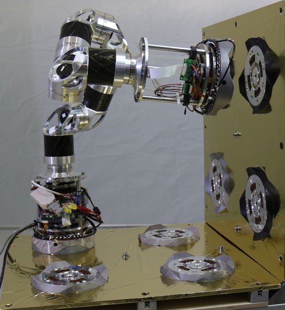
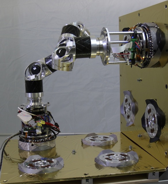
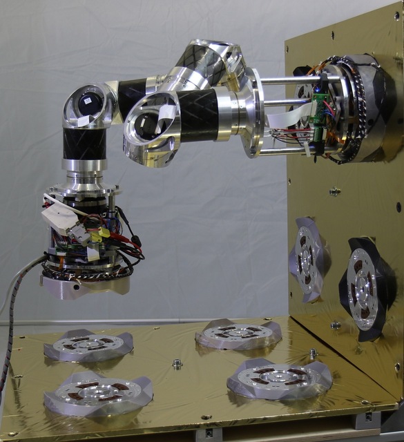
Fig. 9(a)-(b) show an alternation between a regular and an inverted configuration and a repetitive opening and closing of the iSSI interfaces. The tests could be executed autonomously and reproducibly on the horizontal parts of the mockup after a calibration of the robot to the environment. We found that the form fits could compensate only very small offsets during joint position control. When working with uncalibrated environments, active compliance by control will be necessary to compensate for the uncertainty.
Fig. 9(c)-(e) show the approach and the vertical docking of a more distant interface. We needed a manual calibration of the final docking poses in these cases due to a joint-dependent, non-linear structural compliance of the robot under gravity, which leads to individual offsets for each iSSI. The robot’s joint arrangement allowed it to reach these interfaces well.
Fig. 9(f) shows ReCoBot lifting its base to transition into an inverted docking. We teleoperated the robot via the virtual 6D handle and could steer the end-effector with sufficient accuracy in Cartesian axes.
In our experiments, we frequently reached the supported torque limits of the smaller motors in vertical docking scenarios, even with comparatively slow execution speeds. This torque limitation together with the gravity-induced uncertainty, however, will play no role in the envisioned zero-gravity environment of on-orbit manipulation.
VIII Conclusions and Future Works
This paper presented the ReCoBot, a seven-axis robotic manipulator for on-orbit locomotion on iSSI compatible satellites. The system uses two end-effector mounted iSSI interfaces for docking and realizes locomotion planning and teleoperation with Moveit and ROS-control. Experiments evaluated the validity of the proposed concepts for mechanics and electronics in docking maneuvers on a mockup. Future work could consider torque optimal planning [19] for reduced energy consumption. The integration of additional end-effector force-torque sensors and active compliant control could compensate for uncertainty with force-sensitive docking. We will further investigate the possibility of space qualification of ReCoBot in its current state, and consider software-side safety and redundancy through a switch to ROS2 [20] with real-time context [21].
References
- [1] Alex Ellery, Joerg Kreisel and Bernd Sommer “The case for robotic on-orbit servicing of spacecraft: Spacecraft reliability is a myth” In Acta Astronautica 63.5, 2008, pp. 632–648 DOI: https://doi.org/10.1016/j.actaastro.2008.01.042
- [2] V Dubanchet et al. “EROSS project–European Autonomous Robotic Vehicle for on-orbit servicing” In International Symposium on Artificial Intelligence, Robotics and Automation in Space (i-SAIRAS), 2020
- [3] M Kortman et al. “Building block based iBoss approach: fully modular systems with standard interface to enhance future satellites” In 66th International Astronautical Congress (IAC), 2015, pp. 1–11
- [4] Joerg Kreisel, Thomas A. Schervan and Kai-Uwe Schroeder “A Game-Changing Space System Interface Enabling Multiple Modular and Building Block-Based Architectures for Orbital and Exploration Missions” In 70th International Astronautical Congress (IAC), 2019
- [5] Stephanie Koechel and Martin Langer “New Space: Impacts of Innovative Concepts in Satellite Development on the Space Industry” In 69th International Astronautical Congress (IAC), 2018
- [6] Morgan Quigley et al. “ROS: an open-source Robot Operating System” In ICRA workshop on open source software 3.3.2, 2009, pp. 5 Kobe
- [7] Javier Vinals, J Gala and G Guerra “Standard Interface for Robotic Manipulation (SIROM): SRC H2020 OG5 Final Results-Future Upgrades and Applications” In International Symposium on Artificial Intelligence, Robotics and Automation in Space (i-SAIRAS), 2020
- [8] Pierre Letier et al. “HOTDOCK: Design and Validation of a New Generation of Standard Robotic Interface for On-Orbit Servicing” In International Astronautical Congress (IAC), 2020 IAF
- [9] Mathieu Deremetz et al. “MOSAR-WM: A relocatable robotic arm demonstrator for future on-orbit applications” In International Astronautical Congress (IAC), 2020 IAF
- [10] Mathieu Deremetz et al. “Concept of Operations and Preliminary Design of a Modular Multi-Arm Robot using Standard Interconnects for On-Orbit Large Assembly” In International Astronautical Congress (IAC), 2021
- [11] C Zeis et al. “Fully Modular Robotic Arm Architecture Utilizing Novel Multifunctional Space Interface” In IOP Conference Series: Materials Science and Engineering 1226.1, 2022, pp. 012096 IOP Publishing
- [12] M Muñoz Arancón et al. “ESROCOS: a robotic operating system for space and terrestrial applications” In 14th Symposium on Advanced Space Technologies in Robotics and Automation (ASTRA 2017), 2017, pp. pp–1
- [13] Samuel Rader, Lukas Kaul, Pascal Weiner and Tamim Asfour “Highly integrated sensor-actuator-controller units for modular robot design” In 2017 IEEE International conference on advanced intelligent mechatronics (AIM), 2017, pp. 1160–1166 IEEE
- [14] David Coleman, Ioan Sucan, Sachin Chitta and Nikolaus Correll “Reducing the barrier to entry of complex robotic software: a moveit! case study” In Journal of Software Engineering for Robotics 5.1, 2014, pp. 3–16 DOI: 10.6092/JOSER_2014_05_01_p3
- [15] Sachin Chitta et al. “ros_control: A generic and simple control framework for ROS” In The Journal of Open Source Software, 2017 DOI: 10.21105/joss.00456
- [16] Stefan Scherzinger, Arne Roennau and Rüdiger Dillmann “Virtual Forward Dynamics Models for Cartesian Robot Control”, 2020 arXiv: https://arxiv.org/abs/2009.11888
- [17] S. Scherzinger, A. Roennau and R. Dillmann “Inverse Kinematics with Forward Dynamics Solvers for Sampled Motion Tracking” In 19th International Conference on Advanced Robotics (ICAR), 2019, pp. 681–687 DOI: 10.1109/ICAR46387.2019.8981554
- [18] Sertac Karaman and Emilio Frazzoli “Sampling-based algorithms for optimal motion planning” In The international journal of robotics research 30.7 Sage Publications Sage UK: London, England, 2011, pp. 846–894
- [19] Mrinal Kalakrishnan et al. “STOMP: Stochastic trajectory optimization for motion planning” In 2011 IEEE international conference on robotics and automation, 2011, pp. 4569–4574 IEEE
- [20] Yuya Maruyama, Shinpei Kato and Takuya Azumi “Exploring the performance of ROS2” In Proceedings of the 13th International Conference on Embedded Software, 2016, pp. 1–10
- [21] Lennart Puck et al. “Distributed and synchronized setup towards real-time robotic control using ROS2 on Linux” In 2020 IEEE 16th International Conference on Automation Science and Engineering (CASE), 2020, pp. 1287–1293 IEEE