Kondo cooling in quantum impurity systems
Abstract
The Peltier effect is the reverse phenomenon of the Seebeck effect, and has been observed experimentally in nanoscale junctions. However, despite its promising applications in local cooling of nanoelectronic devices, the role of strong electron correlations on such a phenomenon is still unclear. Here, by analyzing the thermoelectric properties of quantum impurity systems out of equilibrium, we unveil the essential role of electron-electron interactions and quantum resonant states in Peltier cooling, leading to the prediction of the Kondo cooling phenomenon. The existence of such Kondo cooling is validated by a reverse heat current and a lowered local temperature in a model junction. The discovery of this unconventional Peltier cooling offers a new approach toward nano-refrigeration, and highlights the unique role of strong electron correlations in nonequilibrium quantum systems.
Introduction.– The Peltier effect is a fundamental thermoelectric phenomenon. It means that when an electric current is passed through a junction connecting two conductors (A and B), heat will be transferred from A to B, which may lead to cooling in A. Peltier refrigerators giazotto2006opportunities ; Muhonen2012Micrometre have been designed and applied to cool various types of electronic devices Rowe1983Modern ; nolas2001thermoelectrics ; phelan2002current ; rowe2006thermoelectrics ; bakker2010interplay ; Flipse2012Direct . This is very appealing for practical purposes, because otherwise the local heat generation and accumulation will likely deteriorate the performances of, or cause damages to the electronic devices.
In the past decade, Peltier cooling in nanoscopic systems has attracted enormous theoretical d2006local ; huang2007local ; galperin2009cooling ; liu2011effect ; dubi2011colloquium ; finch2009giant ; bergfield2010giant ; karlstrom2011increasing ; santhanam2016thermal ; saffarzadeh2018thermoelectric and experimental grosse2011nanoscale ; vera2016direct ; cui2018peltier ; jin2018exploring ; uchida2018observation ; das2019systematic ; wang2020magneto ; zhang2020exploring ; hu2020enhanced ; hubbard2020electron efforts. Thanks to the impressive advances in the synthesis, fabrication and manipulation of nano-sized materials, Peltier cooling has been realized in molecular junctions grosse2011nanoscale ; vera2016direct ; cui2018peltier ; hu2020enhanced ; hubbard2020electron , organic thermoelectric flakes jin2018exploring ; zhang2020exploring , and ferromagnetic/ferrimagnetic metal films uchida2018observation ; das2019systematic ; wang2020magneto . For instance, Cui et al. have directly observed the Peltier cooling in gold junctions with conjugated molecules, and also revealed the relationship between cooling and electron transport characteristics cui2018peltier .
Despite the remarkable progress, the strength of cooling in nanojunctions has not met the needs of practical applications. For instance, the measured cooling power in Ref. [cui2018peltier, ] is lower than nanowatt, thus leaving plenty of room for improvement. Theoretically, the Peltier effect in nanojunctions has been explored within the Landauer theory of quantum transport landauer1957spatial ; buttiker1985generalized ; frensley1990boundary ; meir1992landauer ; Meir1993Low ; jauho1994time ; beenakker1997random ; imry1997introduction ; dresselhaus1998physical ; nitzan2003electron ; Galperin2006Molecular ; galperin2007molecular ; di2008electrical ; galperin2009cooling ; cui2018peltier . However, the cause of the limited cooling magnitude is largely unclear. Moreover, although the influence of electron-electron interactions and the presence of quantum resonant states on local heating of nanojuntions was widely studied huang2007local ; ioffe2008detection ; ward2011vibrational ; zeng2021effect , how these features affect the Peltier cooling has remained a topic barely touched upon.
To shed light on the above effects, and to provide new clues to enhancing Peltier cooling, in this Letter we investigate the thermoelectric response of prototypical quantum impurity systems to applied voltages by means of theoretical analysis and numerical simulations. Particularly, to accentuate the possible role of quantum resonance and electron correlations, we shall focus on systems which explicitly involve electron-electron interactions, while the influence of phonons is omitted. We then predict an unconventional Peltier effect, we call Kondo cooling, which is the direct result of electron correlations. This phenomenon can be readily verified experimentally and offers a new path toward nano-refrigeration.
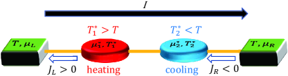
Peltier cooling with Kondo resonant states.– Let us first provide a simple analytical picture of the Kondo cooling phenomenon. Without loss of generality, the nanojunctions are represented by a number of localized impurities embedded between two leads. We first clarify that the electronic Peltier cooling cannot exist in a single-impurity junction. This is because when an electron is driven by a bias to traverse the junction, it gains energy from the work done by the electric field. Such excess energy must dissipate into the surrounding (leads) in the form of heat to conserve energy and thus sustain the stationary state of the junction. Consequently, a single impurity in the junction has no choice but to behave as a hot spot to release the heat. In contrast, if there is more than one impurity in the junction, it is possible to have one impurity cooled down by the Peltier effect, at the expense of heating up the other impurity. For the sake of discussion, we then consider a junction consisting of two impurities connected serially to two metallic leads; see Fig. 1.
By driving a steady electric current through the junction, the heat current produced by the Peltier effect is vera2016direct , where and are the Peltier coefficients of the two-impurity complex and the leads, respectively, and usually bakker2010interplay . Meanwhile, the impurities are also subject to Joule heating with the power , which is caused by electron scattering within the impurities or at the impurity-lead interfaces. Thus, in the context of Fig. 1, the net heat currents flowing into the two leads are
| (1) |
where and are the Joule heat dissipated into the and leads, respectively, with , and and being the local electrochemical potentials of the impurities and . As depicted in Fig. 1, the cooling of impurity- is indicated by a local temperature zhang2019local ; Supplementary , , lower than the background temperature, , of the leads (), as well as a reverse heat current flowing from lead- to impurity-, i.e.,
| (2) |
Here, the voltage drop is assumed to be antisymmetric across the junction, and we have used the second Thomson relation Rowe1983Modern ; nolas2001thermoelectrics ; rowe2006thermoelectrics , with being the thermopower (or Seebeck coefficient) zuev2009thermoelectric ; wei2009anomalous ; checkelsky2009thermopower of the two-impurity complex ziman2001electrons ; wierzbicki2010electric . Clearly, a large negative is an essential prerequisite for the cooling of impurity-.
The zero-bias thermopower can be expressed by the following Landauer-like formula Don0211747 ; Ye2014Thermopower (consider the wide-band limit for the leads and set )
| (3) |
Here, is the normalized spectral density of the impurities, is the Fermi function, and defines a thermal activation window, which is centered at the equilibrium chemical potential and the width is determined solely by Ye2014Thermopower . The value of under a zero or low bias is thus dictated by the lineshape of within such a thermal energy window.
In general, a quantum resonant state is manifested by a single spectral peak in . From Eq. (3), it is clear that a sharp resonance peak located within the left (right) half of the thermal activation window will contribute a significant positive (negative) value to . Besides, resonant states also provide ballistic channels for the electron transport, leading to an increased . Therefore, quantum resonant states located slightly off the lead chemical potential tend to boost a reverse heat current, and hence will greatly enhance the Peltier cooling.
Among the various types of quantum resonant states, those arising due to strong electron correlations are particularly intriguing, since a low background temperature is typically required to suppress the thermal fluctuations which impair the electron correlations. Therefore, by exploiting the concomitant effect of Peltier cooling and strong electron correlations, it is possible to create a local spot that is cooler than the already cool surrounding.
As is well known, the screening of a localized spin moment by the conduction electrons in a metallic lead gives rise to spin-Kondo (S-Kondo) states Goldhaber1998Kondo ; Cronenwett1998Tunable ; Eto2000Enhancement ; Pustilnik2001Kondo ; Fuhrer2004Kondo ; Heersche2006Kondo ; Baruselli2012Kondo at the impurity-lead interface. Their characteristic spectral feature is a sharp resonance peak centered at . Because of the symmetric lineshape of the spectral peak, while S-Kondo states enhance the junction conductance Svilans2018Thermoelectric , they have little influence on the thermopower Ye2014Thermopower .
On the other hand, if the electrons are subject to a strong inter-impurity repulsion, the orbital moment of the two-impurity complex will behave like a pseudospin, and its interaction with the leads will result in the formation of orbital-Kondo (O-Kondo) states Jarillo2005Orbital ; Choi2005SU4Kondo ; Potok2007Observation ; kuemmeth2008coupling ; Fang2008Kondo ; Karolak2011Orbital ; amasha2013pseudospin . The O-Kondo spectral signature is a pair of satellite peaks located on either side of (see also below). Based on Eq. (3), the value of can then be significantly varied by adjusting the relative heights of these two satellite peaks, which can be realized by tuning the energetic structures of the impurities Ye2014Thermopower .
The above analysis predicts unambiguously that further cooling of an already cool impurity can be realized by invoking O-Kondo states in the junction. In the following, we shall validate such a prediction by performing accurate numerical simulations on a prototypical quantum impurity model.
Model and Methodology.– The total Hamiltonian of the junction assumes the form of an Anderson impurity model (AIM) anderson1961localized , . Specifically, the two impurities are described by , where , with () creating (annihilating) a spin- electron on impurity-; and are the intra- and inter-impurity electron-electron interaction energies, respectively; and is the hopping integral between the two impurities. represents the metallic leads, with () being the creation (annihilation) operator for orbital- of lead- (); and describes the electron transfer couplings between the impurities and the leads, with being the coupling strengths.
The thermoelectric properties of the junction are determined by a hierarchical equations of motion (HEOM) method Tanimura1989Time ; jin2008exact ; li2012hierarchical ; Ye2016HEOM ; Han2018On ; Cui2019Highly ; Zhang2020Hierarchical , which has been widely adopted to investigate strongly correlated quantum impurity systems out of equilibrium zheng2013kondo ; Ye2016HEOM ; Wang2018Precise ; li2020molecular ; li2021reaction . In the framework of HEOM, the influence of the metallic leads are fully captured by hybridization functions which assume a Lorentzian form of , with being the hybridization strength and the band width of the leads. The results of HEOM are numerically exact provided that they fully converge with respect to the truncation of the hierarchy Tanimura2020Numerically .
The realization of local cooling at impurity- is characterized by two criteria: (i) a reverse (negative) heat current flowing into impurity- from lead-, , whose magnitude represents the power of Peltier cooling; and (ii) a lower local temperature than the background temperature, as represented by a negative ratio . For the former, the energy spectrum of heat current is calculated via the Landauer formula meir1992landauer ; Supplementary and . For the latter, is determined by an operational protocol based on a minimal perturbation condition (MPC) zhang2019local ; ye2015local ; ye2016thermodynamic ; zeng2021effect ; Supplementary , and the values agree closely to those given by other definitions bergfield2013probing ; bergfield2015tunable ; shastry2016temperature ; shastry2020scanning in the low bias region (see also Supplementary Material).
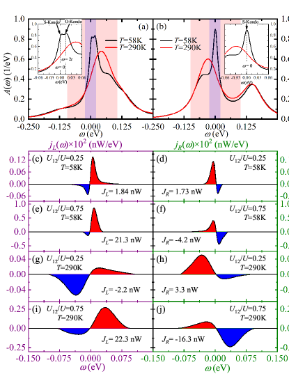
Numerical demonstration of Kondo cooling.– Figure 2(a) depicts the spectral features of Kondo resonant states in the presence of a strong inter-impurity interaction (). Under a cryogenic temperature of K, an S-Kondo peak shows up at . Meanwhile, an O-Kondo peak emerges at , whereas its opposite counterpart at is invisible. Based on Eqs. (2) and (3), the asymmetric lineshape of around will give rise to a large negative , and hence a reverse heat current from lead- to impurity-, i.e., . It is thus predicted that impurity- is cooled down below the low background . In contrast, with a much weaker inter-impurity interaction (), the O-Kondo signature vanishes almost completely; see Fig. 2(b). The resulting symmetric spectral function around will lead to a rather small thermopower . Consequently, the Peltier cooling is overwhelmed by Joule heating at the both impurities, i.e., and .
At room temperature ( K), the Kondo states are completely destroyed. The thermopower is instead dominated by the non-Kondo resonant state whose spectral signature is a resonance peak located at . Since the peak center shifts from negative to positive energy as strengthens, will vary from a positive maximum to a negative maximum, leading to the alternation of local cooling site from impurity- (negative ) to impurity- (negative ).
The above prediction on the values of and the signs of is validated by the calculated nonequilibrium transport properties. Figure 2(c)-(j) display under an antisymmetric bias. Under K, distribute tightly around zero energy, where Kondo resonant states contribute predominantly to the electron and heat transport. Particularly, in the case of a strong , negative is promoted in the energy range spanned by the O-Kondo spectral peak; see Fig. 2(f). In contrast, under K, distributes over a broader energy range, with large negative values emerging at around .
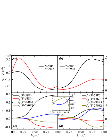
Figure 3 gives an overview of how the Peltier cooling is enabled by varying . Under a cryogenic temperature, a strengthened leads to an enhanced O-Kondo resonance, which in turn elevates the thermopower and conductance of the junction. The resultant Kondo cooling of impurity- is confirmed by the fact that both the two criteria, and , are met with a sufficiently large ; see Fig. 3(c) and (d). Since the MPC-based protocol for the determination of does not require any information on heat currents, and are calculated independently. It is thus remarkable that the variation of with respect to exhibits a very similar trend to that of , albeit with a slightly different turning point from heating to cooling.
Local cooling also happens when the Kondo states are all quenched at room temperature. Figure 3(c) and (d) reveal the same trend with impurity-1 subject to marginal cooling with a weak , while the cooling site shifts to impurity-2 with a sufficiently strong . This verifies the above prediction on the alternation of the local cooling site.
Unlike Kondo resonant states whose energies are intrinsically pinned to the leads’ chemical potential, the positions of non-Kondo resonance peaks depend sensitively on the molecular orbital energies of the embedded impurities. Therefore, to have prominent non-Kondo cooling in practical applications, it is essential to shift the resonance energies, such as the energy of the highest occupied molecular orbital (HOMO) or lowest unoccupied molecular orbital (LUMO) of a molecular device, into the thermal activation window. In contrast, the key to realizing conspicuous Kondo cooling is to produce strong O-Kondo resonant states which distribute asymmetrically with respect to the leads’ chemical potential.
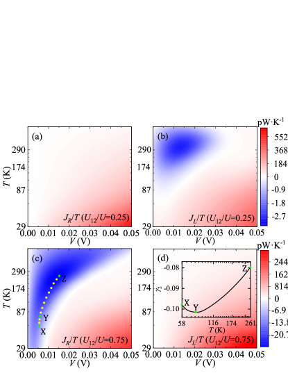
To explore the full range of external conditions under which the Peltier cooling occurs, we plot in Fig. 4 the heat currents scaled by the thermal energy, , as a function of and . Clearly, the cooling regions (shaded in blue) exhibit distinct patterns in the cases of weak and strong . In the former case, local cooling takes effect at impurity- (corresponding to a positive ) within a rather narrow range of and ; see Fig. 4(b). There, the cooling arises entirely from non-Kondo resonance. The absence of Kondo cooling under a low is due to the inactive O-Kondo effect. In contrast, with a strong , local cooling exists at impurity- within a wide range of and ; see Fig. 4(c). Nevertheless, Kondo cooling comes into play only in the lower-left corner (low and low ), since either the intensified thermal fluctuations or the increased mismatch between and will quench the Kondo states Meir1993Low ; Franceschi2002Out ; Altland2009Nonequilibrium ; Cohen2014Green ; Antipov2016Voltage .
The crossover from Kondo cooling to non-Kondo cooling is indicated by a path marked in Fig. 4(c) (the dotted line), along which the variation of is depicted in the inset of Fig. 4(d). It is remarkable that the Kondo resonance actually gives rise to an even greater relative drop of local temperature than the non-Kondo resonance. Figure 4 thus highlights the important role of O-Kondo resonant states, as they are uniquely efficacious in further cooling of an already cool spot to produce an appreciable cooling power.
Concluding remarks.– In summary, we have predicted an unconventional Peltier cooling phenomenon, Kondo cooling, in quantum impurity systems. It arises due to the crucial roles of electron-electron interactions and quantum resonances. We have validated such a prediction numerically on a model junction. The existence of such prominent Kondo cooling is clearly indicated by the reverse heat current and a lowered local temperature, which originate from the orbital-Kondo resonant states distributed unevenly around the chemical potential. This unconventional Kondo cooling phenomenon offers both a new route toward nano-refrigeration and further reveals the importance of strong electron correlations in nonequilibrium quantum systems.
Acknowledgements.
R.X. and X.Z. acknowledge the support from the National Natural Science Foundation of China (Grant Nos. 21973086 and 21633006), the Ministry of Education of China (111 Project Grant No. B18051), and the Fundamental Research Funds for the Central Universities (Grant No. WK2060000018). The computational resources are provided by the Supercomputing Center of University of Science and Technology of China.References
- (1) F. Giazotto, T. T. Heikkilä, A. Luukanen, A. M. Savin, and J. P. Pekola, Rev. Mod. Phys. 78, 217 (2006).
- (2) J. T. Muhonen, M. Meschke, and J. P. Pekola, Rep. Progr. Phys. 75, 046501 (2012).
- (3) D. M. Rowe and C. M. Bhandari, Modern Thermoelectrics, Holt Reinhart and Winston, London, 1983.
- (4) G. S. Nolas, J. Sharp, and J. Goldsmid, Thermoelectrics: Basic Principles and New Materials Developments, Springer, Berlin, 2001.
- (5) P. E. Phelan, V. A. Chiriac, and T.-Y. T. Lee, IEEE Trans. Compon. Packag. Technol. 25, 356 (2002).
- (6) D. M. Rowe, Thermoelectrics Handbook: Macro to Nano, CRC Press, Boca Raton, 2006.
- (7) F. L. Bakker, A. Slachter, J.-P. Adam, and B. J. van Wees, Phys. Rev. Lett. 105, 136601 (2010).
- (8) J. Flipse, F. L. Bakker, A. Slachter, F. K. Dejene, and B. J. van Wees, Nat. Nanotechnol. 7, 166 (2012).
- (9) R. D’Agosta, N. Sai, and M. Di Ventra, Nano Lett. 6, 2935 (2006).
- (10) Z. Huang, F. Chen, R. D’Agosta, P. A. Bennett, M. Di Ventra, and N. Tao, Nat. Nanotechnol. 2, 698 (2007).
- (11) M. Galperin, K. Saito, A. V. Balatsky, and A. Nitzan, Phys. Rev. B 80, 115427 (2009).
- (12) Y.-S. Liu, B. C. Hsu, and Y.-C. Chen, J. Phys. Chem. C 115, 6111 (2011).
- (13) Y. Dubi and M. Di Ventra, Rev. Mod. Phys. 83, 131 (2011).
- (14) C. M. Finch, V. M. García-Suárez, and C. J. Lambert, Phys. Rev. B 79, 033405 (2009).
- (15) J. P. Bergfield, M. A. Solis, and C. A. Stafford, ACS Nano 4, 5314 (2010).
- (16) O. Karlström, H. Linke, G. Karlström, and A. Wacker, Phys. Rev. B 84, 113415 (2011).
- (17) P. Santhanam and S. Fan, Phys. Rev. B 93, 161410(R) (2016).
- (18) A. Saffarzadeh, F. Demir, and G. Kirczenow, Phys. Rev. B 98, 115436 (2018).
- (19) K. L. Grosse, M.-H. Bae, F. Lian, E. Pop, and W. P. King, Nat. Nanotechnol. 6, 287 (2011).
- (20) I. J. Vera-Marun, J. J. van den Berg, F. K. Dejene, and B. J. van Wees, Nat. Commun. 7, 1 (2016).
- (21) L. Cui, R. Miao, K. Wang, D. Thompson, L. A. Zotti, J. C. Cuevas, E. Meyhofer, and P. Reddy, Nat. Nanotechnol. 13, 122 (2018).
- (22) W. Jin, L. Liu, T. Yang, H. Shen, J. Zhu, W. Xu, S. Li, Q. Li, L. Chi, C.-a. Di, and D. Zhu, Nat. Commun. 9, 3586 (2018).
- (23) K.-i. Uchida, S. Daimon, R. Iguchi, and E. Saitoh, Nature 558, 95 (2018).
- (24) R. Das, R. Iguchi, and K.-i. Uchida, Phys. Rev. Applied 11, 034022 (2019).
- (25) J. Wang, Y. K. Takahashi, and K.-i. Uchida, Nat. Commun. 11, 2 (2020).
- (26) F. Zhang and C.-a. Di, Chem. Mater. 32, 2688 (2020).
- (27) X. Hu, X. Gong, M. Zhang, H. Lu, Z. Xue, Y. Mei, P. K. Chu, Z. An, and Z. Di, Small 16, 1907170 (2020).
- (28) W. A. Hubbard, M. Mecklenburg, J. J. Lodico, Y. Chen, X. Y. Ling, R. Patil, W. A. Kessel, G. J. K. Flatt, H. L. Chan, B. Vareskic, G. Bal, B. Zutter, and B. C. Regan, ACS Nano 14, 11510 (2020).
- (29) R. Landauer, IBM J. Res. Dev. 1, 223 (1957).
- (30) M. Büttiker, Y. Imry, R. Landauer, and S. Pinhas, Phys. Rev. B 31, 6207 (1985).
- (31) W. R. Frensley, Rev. Mod. Phys. 62, 745 (1990).
- (32) Y. Meir and N. S. Wingreen, Phys. Rev. Lett. 68, 2512 (1992).
- (33) Y. Meir, N. S. Wingreen, and P. A. Lee, Phys. Rev. Lett. 70, 2601 (1993).
- (34) A.-P. Jauho, N. S. Wingreen, and Y. Meir, Phys. Rev. B 50, 5528 (1994).
- (35) C. W. J. Beenakker, Rev. Mod. Phys. 69, 731 (1997).
- (36) Y. Imry, Introduction to Mesoscopic Physics, Oxford University Press, Oxford, 1997.
- (37) G. Dresselhaus, M. S. Dresselhaus, and R. Saito, Physical Properties of Carbon Nanotubes, Imperial College Press, London, 1998.
- (38) A. Nitzan and M. A. Ratner, Science 300, 1384 (2003).
- (39) M. Galperin, A. Nitzan, and M. A. Ratner, Phys. Rev. Lett. 96, 166803 (2006).
- (40) M. Galperin, M. A. Ratner, and A. Nitzan, J. Phys.: Condens. Matt. 19, 103201 (2007).
- (41) M. Di Ventra, Electrical Transport in Nanoscale Systems, Cambridge University Press, Cambridge, 2008.
- (42) Z. Ioffe, T. Shamai, A. Ophir, G. Noy, I. Yutsis, K. Kfir, O. Cheshnovsky, and Y. Selzer, Nat. Nanotechnol. 3, 727 (2008).
- (43) D. R. Ward, D. A. Corley, J. M. Tour, and D. Natelson, Nat. Nanotechnol. 6, 33 (2011).
- (44) X. Zeng, L. Ye, D. Zhang, R.-X. Xu, X. Zheng, and M. Di Ventra, Phys. Rev. B 103, 085411 (2021).
- (45) Y. M. Zuev, W. Chang, and P. Kim, Phys. Rev. Lett. 102, 096807 (2009).
- (46) P. Wei, W. Bao, Y. Pu, C. N. Lau, and J. Shi, Phys. Rev. Lett. 102, 166808 (2009).
- (47) J. G. Checkelsky and N. P. Ong, Phys. Rev. B 80, 081413(R) (2009).
- (48) D. Zhang, X. Zheng, and M. Di Ventra, Phys. Rep. 830, 1 (2019).
- (49) See Supplemental Material at http://link.aps.org/supplemental for details about the determination of local temperature and local chemical potential, and the energy spectra of electric and heat currents.
- (50) J. M. Ziman, Electrons and Phonons: The Theory of Transport Phenomena in Solids, Oxford University Press, Oxford, 2001.
- (51) M. Wierzbicki and R. Świrkowicz, Phys. Rev. B 82, 165334 (2010).
- (52) B. Dong and X. L. Lei, J. Phys.: Condens. Matter 14, 11747 (2002).
- (53) L. Z. Ye, D. Hou, R. Wang, D. Cao, X. Zheng, and Y. J. Yan, Phys. Rev. B 90, 165116 (2014).
- (54) D. Goldhaber-Gordon, H. Shtrikman, D. Mahalu, D. Abusch-Magder, U. Meirav, and M. A. Kastner, Nature 391, 156 (1998).
- (55) S. M. Cronenwett, T. H. Oosterkamp, and L. P. Kouwenhoven, Science 281, 540 (1998).
- (56) M. Eto and Y. V. Nazarov, Phys. Rev. Lett. 85, 1306 (2000).
- (57) M. Pustilnik and L. I. Glazman, Phys. Rev. Lett. 87, 216601 (2001).
- (58) A. Fuhrer, T. Ihn, K. Ensslin, W. Wegscheider, and M. Bichler, Phys. Rev. Lett. 93, 176803 (2004).
- (59) H. B. Heersche, Z. de Groot, J. A. Folk, L. P. Kouwenhoven, H. S. J. van der Zant, A. A. Houck, J. Labaziewicz, and I. L. Chuang, Phys. Rev. Lett. 96, 017205 (2006).
- (60) P. P. Baruselli, A. Smogunov, M. Fabrizio, and E. Tosatti, Phys. Rev. Lett. 108, 206807 (2012).
- (61) A. Svilans, M. Josefsson, A. M. Burke, S. Fahlvik, C. Thelander, H. Linke, and M. Leijnse, Phys. Rev. Lett. 121, 206801 (2018).
- (62) P. Jarillo-Herrero, J. Kong, H. S. J. van der Zant, C. Dekker, L. P. Kouwenhoven, and S. De Franceschi, Nature 434, 484 (2005).
- (63) M.-S. Choi, R. López, and R. Aguado, Phys. Rev. Lett. 95, 067204 (2005).
- (64) R. M. Potok, I. G. Rau, H. Shtrikman, Y. Oreg, and D. Goldhaber-Gordon, Nature 446, 167 (2007).
- (65) F. Kuemmeth, S. Ilani, D. C. Ralph, and P. L. McEuen, Nature 452, 448 (2008).
- (66) T.-F. Fang, W. Zuo, and H.-G. Luo, Phys. Rev. Lett. 101, 246805 (2008).
- (67) M. Karolak, D. Jacob, and A. I. Lichtenstein, Phys. Rev. Lett. 107, 146604 (2011).
- (68) S. Amasha, A. J. Keller, I. G. Rau, A. Carmi, J. A. Katine, H. Shtrikman, Y. Oreg, and D. Goldhaber-Gordon, Phys. Rev. Lett. 110, 046604 (2013).
- (69) P. W. Anderson, Phys. Rev. 124, 41 (1961).
- (70) Y. Tanimura and R. Kubo, J. Phys. Soc. Jpn. 58, 101 (1989).
- (71) J. Jin, X. Zheng, and Y. J. Yan, J. Chem. Phys. 128, 234703 (2008).
- (72) Z. H. Li, N. H. Tong, X. Zheng, D. Hou, J. H. Wei, J. Hu, and Y. J. Yan, Phys. Rev. Lett. 109, 266403 (2012).
- (73) L. Ye, X. Wang, D. Hou, R.-X. Xu, X. Zheng, and Y. J. Yan, WIREs Comput. Mol. Sci. 6, 608 (2016).
- (74) L. Han, H.-D. Zhang, X. Zheng, and Y. J. Yan, J. Chem. Phys. 148, 234108 (2018).
- (75) L. Cui, H.-D. Zhang, X. Zheng, R.-X. Xu, and Y. J. Yan, J. Chem. Phys. 151, 024110 (2019).
- (76) H.-D. Zhang, L. Cui, H. Gong, R.-X. Xu, X. Zheng, and Y. J. Yan, J. Chem. Phys. 152, 064107 (2020).
- (77) X. Zheng, Y. J. Yan, and M. Di Ventra, Phys. Rev. Lett. 111, 086601 (2013).
- (78) X. Wang, L. Yang, L. Ye, X. Zheng, and Y. J. Yan, J. Phys. Chem. Lett. 9, 2418 (2018).
- (79) X. Li, L. Zhu, B. Li, J. Li, P. Gao, L. Yang, A. Zhao, Y. Luo, J. Hou, X. Zheng, B. Wang, and J. Yang, Nat. Commun. 11, 2566 (2020).
- (80) X. Li, H. Gong, Q. Zhuang, B. Wang, X. Zheng, and J. Yang, J. Phys. Chem. C 125, 21488 (2021).
- (81) Y. Tanimura, J. Chem. Phys. 153, 020901 (2020).
- (82) L. Z. Ye, D. Hou, X. Zheng, Y. J. Yan, and M. Di Ventra, Phys. Rev. B 91, 205106 (2015).
- (83) L. Z. Ye, X. Zheng, Y. J. Yan, and M. Di Ventra, Phys. Rev. B 94, 245105 (2016).
- (84) J. P. Bergfield, S. M. Story, R. C. Stafford, and C. A. Stafford, ACS Nano 7, 4429 (2013).
- (85) J. P. Bergfield, M. A. Ratner, C. A. Stafford, and M. Di Ventra, Phys. Rev. B 91, 125407 (2015).
- (86) A. Shastry and C. A. Stafford, Phys. Rev. B 94, 155433 (2016).
- (87) A. Shastry, S. Inui, and C. A. Stafford, Phys. Rev. Applied 13, 024065 (2020).
- (88) S. De Franceschi, R. Hanson, W. G. van der Wiel, J. M. Elzerman, J. J. Wijpkema, T. Fujisawa, S. Tarucha, and L. P. Kouwenhoven, Phys. Rev. Lett. 89, 156801 (2002).
- (89) A. Altland and R. Egger, Phys. Rev. Lett. 102, 026805 (2009).
- (90) G. Cohen, E. Gull, D. R. Reichman, and A. J. Millis, Phys. Rev. Lett. 112, 146802 (2014).
- (91) A. E. Antipov, Q. Dong, and E. Gull, Phys. Rev. Lett. 116, 036801 (2016).