Designing Underactuated Graspers with Dynamically Variable Geometry Using Potential Energy Map Based Analysis
Abstract
In this paper we present a potential energy map based approach that provides a framework for the design and control of a robotic grasper. Unlike other potential energy map approaches, our framework is able to consider friction for a more realistic perspective on grasper performance. Our analysis establishes the importance of including variable geometry in a grasper design, namely with regards to palm width, link lengths, and transmission ratio. We demonstrate the use of this method specifically for a two-phalanx tendon-pulley underactuated grasper, and show how various design parameters – palm width, link lengths, and transmission ratios – impact the grasping and manipulation performance of a specific design across a range of object sizes and friction coefficients. Optimal grasping designs have palms that scale with object size, and transmission ratios that scale with the coefficient of friction. Using a custom manipulation metric we compared a grasper that only dynamically varied its geometry to a grasper with a variable palm and distinct actuation commands. The analysis revealed the advantage of the compliant reconfiguration ability intrinsic to underactuated mechanisms; by varying only the geometry of the grasper, manipulation of a wide range of objects could be performed.
I INTRODUCTION
One of the most daunting challenges still facing the robotics community is the design and control of robot graspers. A practical robot must be able to reliably grasp and manipulate a wide range of objects and yet be simple to use. As applications of robots expand from industrial use to performing everyday tasks in domestic environments, solving this problem becomes increasingly imperative. Currently, most research focuses on the algorithmic side of grasping and manipulation systems that can have practical applications outside of the lab. However, grasping and manipulation are not one-dimensional problems; a hand will only be as capable and dexterous as its hardware allows [1, 2]. Naturally, this led researchers to attempt to match task diversity by approximating the versatility of the human hand [3]. While some pursuits have found success [4], the state of the art is far from being practical. We believe there is an optimal middle ground that involves mechanically intelligent graspers and clever control algorithms to match.
A particular area of promise involves underactuated graspers. Consisting of fewer actuators than degrees of freedom, these graspers exhibit an inherent compliance that enables them to gently conform to a diverse set of objects without requiring complex control schemes [5, 6]. However, intentional parameter choices are fundamental to realizing the desired conforming behavior. Careful selection of elastic elements and joint limits resolves the motion indeterminacy of the finger in free space and dictate the closing sequence of the phalanges. Contact forces and grasp stability are also notably reliant on the finger design. Through deliberate design decisions, the intrinsic conforming behavior of underactuated graspers can be leveraged to maximize caging grasps [7, 8]. Caging an object introduces a set of constraints from the grasper, preventing the object from moving to an arbitrarily far point away from the grasper workspace. Caging grasps are important for secure transport during pick-and-place tasks, since the object can move with the robot even in the absence of large contact forces [9]. Additionally, Bircher et al. used a fully-actuated grasper to show that caging grasps are essential for performing safe in-hand manipulation [10]. Given their significance, designing graspers geared toward caging is a promising direction.
However, underactuated graspers are not without their limitations. Similar to any grasper, their geometry restricts them from grasping a wide range of objects. For objects larger than the palm width of the grasper, the contact normals of the proximal links are directed away from the palm, making it difficult to draw the object into a secure grasp. A fully actuated finger may overcome this by applying additional torque at distal joints; however, an underactuated grasper has traded mechanical intelligence at the cost of controllability and thus lacks direct influence over individual joints. Another limitation, specific to the tendon-driven mechanisms studied in this work, is the presence of torque scaling at the joints [6]. This phenomenon is essential for both the conforming behavior and preventing phalanx rollback. However, it can necessitate the application of significant actuation torques to draw an object in, which is undesirable for fragile objects.
In order to overcome the geometrical limitations of underactuated graspers, some researchers have incorporated dynamically changing geometry into their designs. Geometrical variation is usually introduced into the palm of a grasper. Finger splaying for grasping large objects and collapsing of the palm through bending in order to grasp small objects was attainable using a pneumatically actuated palm [11]. A vacuum actuated palm allowed the grasper to cage objects of various sizes and achieve favorable contact points on irregular objects [12]. Other graspers have featured fingers that could slide toward and away from the center of the palm, effectively changing the palm width in order to grasp a variety of object sizes [13, 14]. Variable transmission ratios, which relate the actuation torque to joint torques, are also paramount; secure power grasps can be achieved by varying the transmission ratio as the pulley radii change [15], and force isotropy can be maintained throughout a grasping sequence given certain contact locations [16].
In addition to augmenting the grasping potential of an underactuated grasper, researchers have sought to improve their manipulation capabilities despite their inherent lack of controllability. Prehensile manipulation could be performed using the derived relationship between actuator commands and the resulting object-grasper configuration [17, 18]. The concept of potential energy maps, which describes how the energy of the object-grasper system fluctuates throughout the system configuration space, is an encouraging method for intelligent manipulation, applicable to both underactuated and fully-actuated graspers [19, 20, 8, 21, 10]. By understanding the variation of potential energy across different configurations, an object can be driven to desired states. The validity of the method has been shown in simulation via resultant force fields [22] and in physical experiments where friction was kept intentionally low [10]. The computational cost of generating and utilizing potential energy maps for design and planning is low and their functional impact is high. Unfortunately, thus far potential energy map based analyses have neglected to include friction, apart from computationally expensive simulations that do not permit quick, and necessary, design iteration. Friction is imperative to grasping, and has been used to improve both grasping and manipulation and therefore should not be discarded from the analysis [23, 24].
In this work, we utilize a potential energy map based approach to analyze grasper designs on their ability to achieve caging grasps and manipulate objects of varying size and friction coefficients. Previous potential energy map approaches neglected to include friction because they minimize the energy to obtain the finger configuration. This is valid for frictionless systems, since there is a single equilibrium configuration. The introduction of friction causes static indeterminacy, implying multiple equilibrium configurations. We approach the problem the other way: leverage the known closing behavior of an underactuated finger to determine the configuration, and then calculate the energy. We hope that this work will help close the gap between the theorized performance of an analytically designed grasper and the performance achieved in the real world. The inclusion of friction adds an important dimension to the design space; a refined design should excel at grasping and manipulating across a set of varying object geometries and surface properties. Through this approach we demonstrate the necessity of dynamically changing geometry, such as variable palm width, variable link lengths (prismatic links), and variable transmission ratios (changing pulley diameters), in order to realistically grasp and manipulate a diverse set of objects.
II METHODS
We first discuss the assumed grasper model. We then describe how the configuration of the fingers can be determined for any object-grasper position, and how this is related to energy. Finally, we discuss the construction of a given energy map. The method presented here for determining the potential energy of a given object-grasper configuration is specific for two-phalanx tendon-driven fingers, but the approach can be adapted based on the mechanism [5]. The analysis of the potential energy maps presented, specifically with regards to the custom manipulation metric III-B, can be used for any grasper.
II-A Kinematic Model
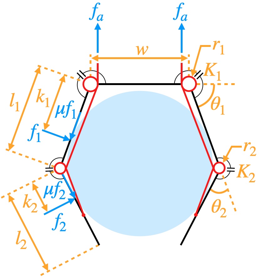
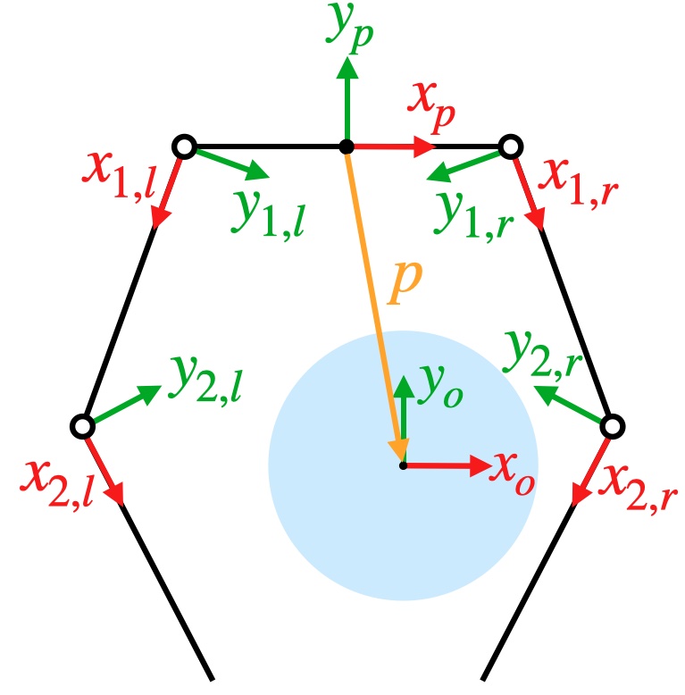
The geometric parameters, forces, and system frames are shown in Fig. 1. The left and right fingers are symmetric in both design – link lengths and , pulley radii and , and joint springs and – and the applied actuation force, . Given a nonzero , the torques at each joint will be equal to and . In response to these torques the finger will reconfigure until the contact forces with a given object result in static equilibrium for the finger. We assume that the spring torques, given by and , are negligible relative to both the actuation torques and the moments applied by the grasped object. However, the springs are necessary to resolve the free space motion indeterminacy of the finger. Specifically, we assume they compel the proximal distal movement behavior described in [6], i.e., the distal phalanx will not move until the proximal phalanx reaches a joint limit or makes contact with the object.
II-B Potential Energy Maps with Friction
Potential energy maps aim to describe the gross motion of an object given a specific actuator command and an initial object-grasper position, defined by in Fig. 1b. These maps are constructed by determining the configuration of the fingers that result in static equilibrium of the grasper as well as the energy of the resulting stable system. In a frictionless system, the equilibrium configuration of the finger can be found by minimizing the energy of each finger of the grasper. For a finger with joints, the joint variable vector , and springs at each joint with spring constant the equilibrium joint angles of the finger can be found by carrying out the minimization in (1) subject to the appropriate contact constraints [19]. Note that is the rest position for each joint.
| (1) |
By solving (1) at each object-grasper configuration, we can predict the gross motion of the object by following potential energy gradients from high potential energy to low potential energy configurations. This was experimentally shown in [7, 10].
II-B1 Stable object-grasper positions with friction
A benefit of continuing to use energy to predict gross object motion is that, similar to conservative systems, non-conservative systems tend to move from high energy to low energy object-grasper positions. However, the inclusion of friction indicates the system may not reach the absolute lowest energy state, but may instead settle at a different, higher energy state where static equilibrium is also achieved. This is analogous to a particle sliding down a convex sloping plane: if we assume the particle will come to a stop, its final potential energy will be equal to , where is the particle’s final height. As increases so does , meaning friction prevents the system from reaching the lowest, desired energy state. The same is true of our object-grasper system.
For the object-grasper system, static equilibrium states are achieved when the convex hull defined by the friction cone edges at each contact point contain the external wrench, . This is shown in (2), where is the grasp matrix for a given finger configuration, is the number of contact points, and is the vector of contact wrenches. For the th contact wrench, where , we have consisting of a tangential force, , a normal force, , and a torsional moment . Since the contact normals lie in the plane . We assume Coulomb friction such that where is the coefficient of static friction (we assume equal static and kinetic coefficients of friction).
| (2) |
In our case we assume that external wrenches on the object are negligible relative to the applied wrenches, i.e., is the null wrench. Before we can use (2) to see if we are at a stable object-grasper position, we need to determine the configuration of fingers that result in static equilibrium of the grasper.
II-B2 Finger configuration determination
The static equilibrium configuration of each finger is needed in order to calculate the potential energy of the system (see II-B3). The procedure for determining the finger configuration at static equilibrium is shown in Algorithm 1 and described below.
We cannot simply use (1) to find the configuration (or system potential energy) because the presence of friction implies multiple finger configurations satisfying static equilibrium. Instead, we need to understand the evolution of the grasp by considering both the vector loop equations and the sign of the proximal contact force [5]. First, a least-squares minimization is performed on the vector loop equations for the proximal link (3) and the distal link (4). If no solution is found, then the object is not reachable.
| (3) | ||||
| (4) |
Next, the sign of the proximal contact force, is investigated using (5) and (6). It is necessary to evaluate (5) for as shown in (7a) - (7c). Given a solution to both (3) and (4) static equilibrium is achieved if is strictly positive (case (7a)), or if we can achieve with since we have sticking (case (7c)). If is strictly negative (case (7b)), then the contact point will slide toward the tip of the distal link until static equilibrium is reached or the object is ejected.
| (5) | ||||
| (6) |
A solution to only (3) implies the proximal link is contacting the object and the distal link has reached its joint limit, thus the sign of does not need to be investigated. If only (4) is satisfied then only the distal link is able to contact the object. Again, cases (7a) and (7c) imply static equilibrium has been achieved, while case (7b) implies reconfiguration.
| (7a) | |||||
| (7b) | |||||
| (7c) |
It should be stated that the specifics of this analysis are for two-phalanx tendon-driven fingers, but can be extended to other underactuated mechanisms such as linkage and gear based fingers. The nature of the contact for these fingers ensures that the distal link will slide on the object and the proximal link will break contact during a finger reconfiguration. For an -link finger with the same proximal to distal closing sequence, grasp stability still remains an open problem [5].
II-B3 System potential energy
We consider the system as the grasper and object. Friction is internal to this system, thus the potential energy can be calculated by the work done by the joint torques and spring torques.
| (8) | ||||
| Just as in (5) and (6) we assume that the springs are negligible and so energy is calculated by only considering the work done on the joints for each finger (left and right): | ||||
| (9) | ||||
where for the th joint is the torque, is the joint angle, and is the initial joint angle. While it may seem that friction has no effect on , it does determine the joint angles required to achieve static equilibrium. As expected, given two identical scenarios (same grasper and ) that differ only in the value of , the scenario with the larger will have a higher value .
II-B4 Potential energy map construction
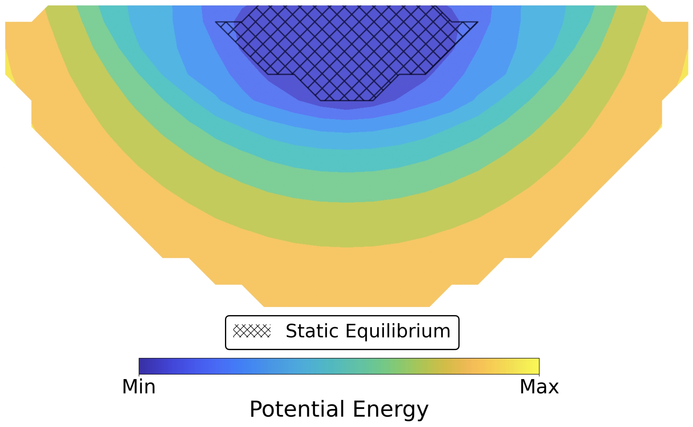
To construct a potential energy map we first fix the grasper, and then move the object through various grid points . Energy map is constructed by plotting the energy found from (9) at each point , where and is the subset of points where the object could be reached. A representative energy map can be seen in Fig. 2 – the hatched areas in Fig. 2 are locations where (2) is satisfied and we therefore assume the object will not move.
Energy maps can be compared depending on the performance requirements of the grasper. One such requirement could be a grasper’s ability to evolve an object into a stable cage and / or stable tip prehension point. To analyze this, we can take each graspable point and follow the gradient of the energy into one of the following types of possible final points :
| (10a) | |||||
| (10b) | |||||
| (10c) |
Contained means that the center of the object is within the polygon formed by the grasper links and palm and is the largest possible object that could escape the grasp [7]. Points where (3) - (6) are satisfied but (2) is not imply that the object is still evolving towards its final grasp, since we do not have force closure. In these cases, we assume the object is quasistatically evolving along the path of least resistance (i.e., following energy gradients). Stable points consist of both caged and tip prehension grasps; we did not consider form closure grasps in our characterizations.
III EXPERIMENTS
The goals our experiments were as follows:
-
•
Determine the best grasper designs defined by their ability to cage a specific object.
-
•
Provide design insights with respect to grasper parameters for a variety of object sizes and friction coefficients.
-
•
Investigate the possible trade-off between caging and tip prehension grasps.
-
•
Compare a grasper with dynamically variable geometry (, , , , and can all actively change) to a set of graspers with only a variable palm, with respect to a custom manipulation metric.
| Parameter | |||||||
|---|---|---|---|---|---|---|---|
| Lower Bound | 0.4 | 0.4 | 0.04 | 0.02 | 0.0 | 0.4 | 0.1 |
| Upper Bound | 2.0 | 1.6 | 0.20 | 0.18 | 2.0 | 1.6 | 1.0 |
| Step Size | 0.2 | 0.4 | 0.04 | 0.04 | 0.4 | 0.4 | 0.3 |
To do this we analyzed the performance of 5,400 grasper designs on 16 objects, defined by the parameters shown in Table I, resulting in a total of 86,400 energy maps. No experiments were run with , because for reconfiguration grasps where two-phalanx contact shifts to single-phalanx contact, the contact point for static equilibrium would need to be located at infinity. The proximal joint limit was set to and the distal joint limit was set to . The 86,400 energy maps were computed in roughly 10 hours on Sherlock, a High Performance Computing Cluster on campus.
III-A Caging Grasps
We scored graspers for a given object by their ability to evolve the object along a trajectory into a caging grasp. Each finger was given the same single actuation force, i.e., . Object trajectories were created using fourth-order Runge-Kutta and linear interpolation. Trajectories that ended in ejection or a tip prehension point were given a score of zero, while trajectories that ended in a cage were scored according to . The score for the th energy map, , was calculated as the following, given points in that ended in a cage:
| (11) |
III-B Manipulation Metric
We considered graspers . Each grasper is able to realize one of discretized grasper designs such that at a given time, where . Each grasper can realize particular command from the set of all actuation commands available for . For a given object , position , grasper design , and actuation command , we can calculate the set of scaled contact wrenches, and its corresponding convex hull . Note that we scale the contact wrenches by the caging score to ensure safe manipulation [10]. Repeating this procedure for each grasper and every actuation command in we can construct the overall convex hull, , given the set of all contact wrenches at for a specific object, .
| (12) |
where is the origin in wrench space. This allows us to consider only the actuation commands and grasper configurations that will impart motion on the object since a specific the set of wrenches do not satisfy (2). Provided that we can determine the maximum wrench magnitude that can be imparted to the object in any direction in the planar wrench space. This is done by finding the radius, , of the maximum sphere that can be inscribed inside [10]. We then define our manipulation metric, , for a given grasper and a given object as follows:
| (13) |
In our tests we considered two types of scenarios:
-
•
Scenario A
-
–
Grasper: Variable , fixed , , , and
-
–
Actuation:
-
–
-
•
Scenario B
-
–
Grasper: Variable , , , , and
-
–
Actuation:
-
–
The graspers for Scenario A were sampled from the best caging grasper designs determined from the experiments described in III-A. Scenario B assumes a grasper that can realize all 5,400 designs in Table I. Note that . We set and sample each finger force, and , in steps of from to . Note that in Scenario B there is only one set of actuation forces (), namely a set of forces specifically geared for pulling the object toward the palm. We computed (13) for each grasper in Scenario A and compared the best design to that for Scenario B, for a given object in O.
IV DISCUSSION
IV-A Caging Ability
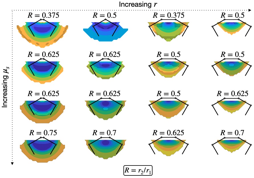
The best grasper design at establishing a caging grasp along with its corresponding energy map for each of the sixteen objects tested can be seen in Fig. 3. Each grasper design shown maximizes its finger length, such that and (the upper bounds of our parameter search). Relative to a grasper with shorter links, longer fingers allow the grasper to reach the given object in more configurations, and to reach further around the object in order to better pull it towards the palm. Both of these will increase by increasing and decreasing .
There are two additional trends to note, which can be seen by looking along the columns (constant object radius ) and along the rows (constant ) in Fig. 3. As has been observed previously [7], a variable palm is useful for grasping objects of different sizes. In the leftmost column of Fig. 3, the palm width is equal to the object radius (), and as the object size increases so does the palm width ( in three of the four cases shown in the second column from the left, and in the right two columns). If the palm is too small, the fingers may not be able to get around the object and pull it into a caging grasp (rightmost columns). On the other hand, both fingers may not be able to reach the object if the palm is too large (leftmost columns).
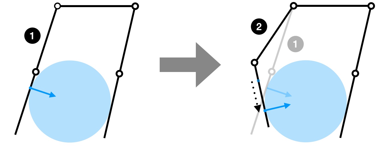
For a given object radius , the optimal transmission ratio () increases as the coefficient of static friction increases. This relationship can be understood by noting the importance of . As shown in Fig. 4, as the distal link rotates, increases and the contact point moves toward the fingertip. This re-positioning allows the finger to slide itself further underneath the object causing the contact normal to be directed more toward the palm, therefore making it easier to pull the object into a caging grasp. The affect of on can be seen by looking at the value of needed to achieve moment equilibrium about the proximal joint when there is distal only contact. In other words, if we set (5) equal to zero and solve for in terms of we get the following:
| (14) |
We can see that and have countering effects; an increase in causes to decrease (undesirable for caging) and an increase in causes to increase (desirable for caging). There are limits, however, since we need for a stable grasp, which constrains the transmission ratio from being excessively large.
IV-B Caging vs. Tip Prehension
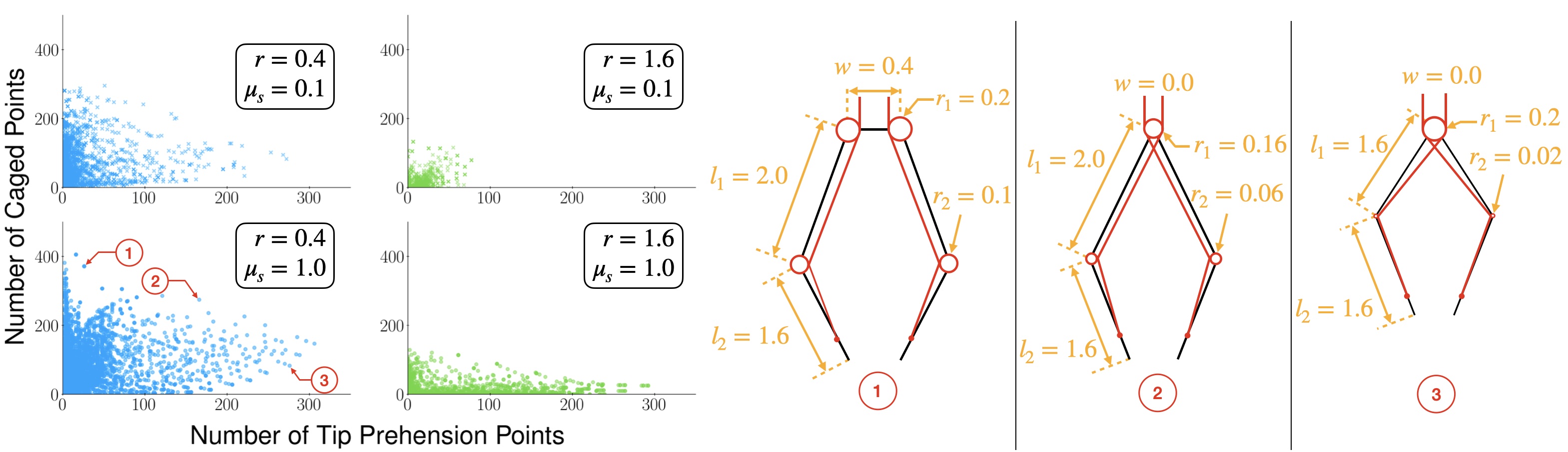
We also investigated how the number of caging and tip prehension grasps changed as a function of and (see Fig. 5). As expected, the number of caging grasps decreased (and the number of tip prehension grasps increased) as the object size increased. A larger object suggests fewer caging grasp configurations as the fingers may not be long enough to favorably position themselves around the object. Additionally, as increased the number of tip prehension grasps increased and the number of caging grasps seemed to decrease. Friction resists an object from being pulled in completely, even when the contact normals point toward the palm, since (2) will be satisfied for more points in as increases. Additionally, sufficient friction permits more tip prehension grasps even when the the contact normals are directed away from the palm. Representative designs that focus on caging, tip prehension, and a compromise between the two for an object with and can be seen in Fig. 5. The designs with more of a focus on caging had a larger transmission ratio (), longer finger lengths ( and ), and a wider palm width () compared to those with a focus on tip prehension grasps. This is in line with the trends noted in the previously section from Fig. 3.
IV-C Manipulation Comparison
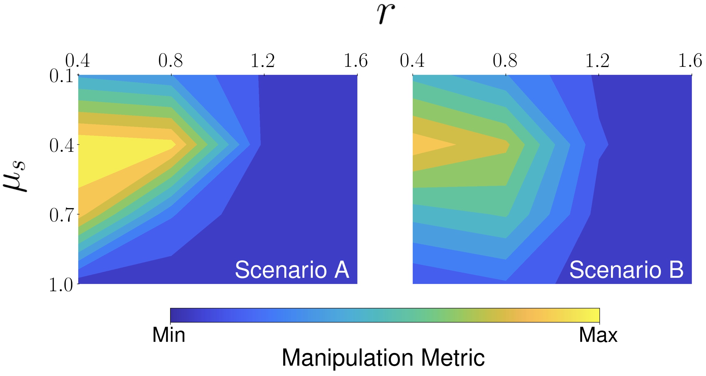
A comparison of Scenario A and Scenario B is shown in Fig. 6. Across all objects, the best grasper from Scenario A had the following parameters:
-
•
Grasper: , , ,
Recall that could swing between the full range of values in Table I. The two graspers performed more closely than expected. Despite executing a single actuation command, Scenario B performed well across a wider variety of objects than Scenario A, particularly for larger objects and objects with higher coefficients of friction. Specifically, Scenario B performed better for eight out of the sixteen objects tested. Objects with and had a manipulation metric score of zero for both scenarios, most likely a result of the high friction resulting in equilibrium combined with insufficiently long fingers with respect to object size in order to achieve a variety of contact wrenches. Interestingly, the best scores were with . We theorize that strikes a perfect balance between spanning the wrench space and not satisfying (2) such that a net wrench is applied to the object.
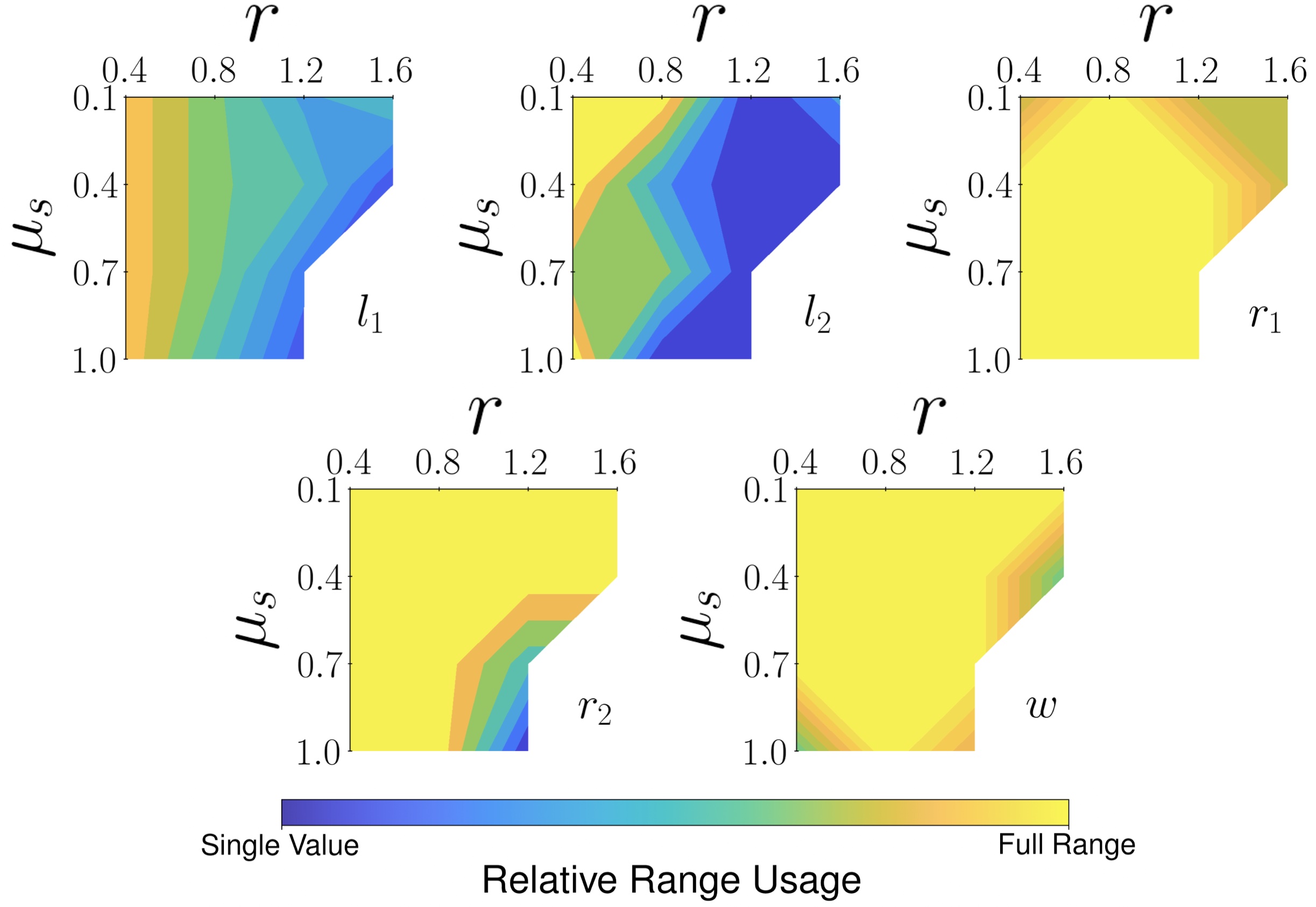
The influence of different parameters for Scenario B on the manipulation metric can be seen in Fig. 7. Lighter colors indicate a larger portion of the realizable range for that parameter is needed for manipulation of a given object. Namely, the pulley radii and the palm width utilized their full range of values for almost every object. Variable link lengths were less important; as object size increased they were pushed to their upper parameter bounds. For smaller objects the distal link realized its full range, while the proximal link mainly adhered to the upper three-fourths of its parameter range. These initial results indicate dynamically changing geometry should primarily be introduced in palm and pulley radii, although link length may play a role for objects smaller than those examined.
V CONCLUSION AND FUTURE WORK
In this paper we present a potential energy map based approach that provides a framework for the design and control of a robotic grasper. Friction was also considered in order to provide a realistic perspective on grasper performance. Through this method we investigated how various design parameters of a tendon-driven underactuated mechanism influence its ability to both grasp and manipulate a distinct set of objects. With regards to establishing caging grasps, both the palm width and transmission ratio were shown to scale with object size and the coefficient of static friction, respectively. We also demonstrated that by dynamically changing its geometry, a grasper excels at manipulating a wider range of objects compared to a grasper with only a variable palm subjected to a diverse set of actuation commands. Despite introducing additional actuators, we were able to show that an underactuated grasper’s grasping and manipulation capabilities are improved and controllable.
In future work, the effect of non-symmetric dynamically varying fingers in conjunction with a set of actuator commands will be explored. We also intend to investigate manipulation scenarios that not only include imparting motion to the object, but also bring an object in motion to a stop, such that it can be stably held throughout the workspace. We will design and build prototypes to validate our findings, as well as develop various potential energy map-based and model-free control schemes for dynamically varying the grasper geometry in order to manipulate an object.
References
- [1] T. Chen, Z. He, and M. Ciocarlie, “Hardware as policy: Mechanical and computational co-optimization using deep reinforcement learning,” arXiv preprint arXiv:2008.04460, 2020.
- [2] H. Ha, S. Agrawal, and S. Song, “Fit2form: 3d generative model for robot gripper form design,” arXiv preprint arXiv:2011.06498, 2020.
- [3] S. R. Company, “Design of a dextrous hand for advanced clawar applications,” CLAWAR, 2003.
- [4] I. Akkaya, M. Andrychowicz, M. Chociej, M. Litwin, B. McGrew, A. Petron, A. Paino, M. Plappert, G. Powell, R. Ribas, et al., “Solving rubik’s cube with a robot hand,” arXiv preprint arXiv:1910.07113, 2019.
- [5] L. Birglen, T. Laliberté, and C. M. Gosselin, Underactuated robotic hands, vol. 40. Springer, 2007.
- [6] S. Hirose and Y. Umetani, “The development of soft gripper for the versatile robot hand,” Mechanism and machine theory, vol. 13, no. 3, pp. 351–359, 1978.
- [7] W. G. Bircher and A. M. Dollar, “Design principles and optimization of a planar underactuated hand for caging grasps,” in 2019 International Conference on Robotics and Automation (ICRA), pp. 1608–1613, IEEE, 2019.
- [8] R. R. Ma, W. G. Bircher, and A. M. Dollar, “Toward robust, whole-hand caging manipulation with underactuated hands,” in 2017 IEEE International Conference on Robotics and Automation (ICRA), pp. 1336–1342, IEEE, 2017.
- [9] A. Rodriguez, M. T. Mason, and S. Ferry, “From caging to grasping,” The International Journal of Robotics Research, vol. 31, no. 7, pp. 886–900, 2012.
- [10] W. G. Bircher, A. S. Morgan, and A. M. Dollar, “Complex manipulation with a simple robotic hand through contact breaking and caging,” Science Robotics, vol. 6, no. 54, 2021.
- [11] H. Wang, F. J. Abu-Dakka, T. N. Le, V. Kyrki, and H. Xu, “A novel soft robotic hand design with human-inspired soft palm: Achieving a great diversity of grasps,” IEEE Robotics & Automation Magazine, vol. 28, no. 2, pp. 37–49, 2021.
- [12] V. Subramaniam, S. Jain, J. Agarwal, and P. Valdivia y Alvarado, “Design and characterization of a hybrid soft gripper with active palm pose control,” The International Journal of Robotics Research, vol. 39, no. 14, pp. 1668–1685, 2020.
- [13] W. Huang, J. Xiao, and Z. Xu, “A variable structure pneumatic soft robot,” Scientific Reports, vol. 10, no. 1, pp. 1–15, 2020.
- [14] Y. Sun, Q. Zhang, and X. Chen, “Design and analysis of a flexible robotic hand with soft fingers and a changeable palm,” Advanced Robotics, vol. 34, no. 16, pp. 1041–1054, 2020.
- [15] S. A. Spanjer, R. Balasubramanian, A. M. Dollar, and J. L. Herder, “Underactuated gripper that is able to convert from precision to power grasp by a variable transmission ratio,” in Advances in Reconfigurable Mechanisms and Robots I, pp. 669–679, Springer, 2012.
- [16] S. Krut, “A force-isotropic underactuated finger,” in Proceedings of the 2005 IEEE International Conference on Robotics and Automation, pp. 2314–2319, IEEE, 2005.
- [17] L. U. Odhner and A. M. Dollar, “Dexterous manipulation with underactuated elastic hands,” in 2011 IEEE International Conference on Robotics and Automation, pp. 5254–5260, IEEE, 2011.
- [18] Q. Lu, N. Baron, A. B. Clark, and N. Rojas, “Systematic object-invariant in-hand manipulation via reconfigurable underactuation: Introducing the ruth gripper,” The International Journal of Robotics Research, vol. 40, no. 12-14, pp. 1402–1418, 2021.
- [19] G. A. Kragten, “Underactuated hands: fundamentals, performance analysis and design,” 2011.
- [20] A. Rodriguez, M. T. Mason, and S. S. Srinivasa, “Manipulation capabilities with simple hands,” in Experimental Robotics, pp. 285–299, Springer, 2014.
- [21] W. G. Bircher, A. S. Morgan, K. Hang, and A. M. Dollar, “Energy gradient-based graphs for planning within-hand caging manipulation,” in 2019 International Conference on Robotics and Automation (ICRA), pp. 2462–2467, IEEE, 2019.
- [22] H. Stuart, S. Wang, O. Khatib, and M. R. Cutkosky, “The ocean one hands: An adaptive design for robust marine manipulation,” The International Journal of Robotics Research, vol. 36, no. 2, pp. 150–166, 2017.
- [23] S. Yuan, A. D. Epps, J. B. Nowak, and J. K. Salisbury, “Design of a roller-based dexterous hand for object grasping and within-hand manipulation,” in 2020 IEEE International Conference on Robotics and Automation (ICRA), pp. 8870–8876, IEEE, 2020.
- [24] J. Salisbury, “Kinematics and force analysis of articulated hands, phd thesis,” 1982.