Automatic Compiler-Based Data Structure Generation
Abstract
Optimizing compilers are mainly equipped to optimize control flow. The optimization of data structures is left to the programmer and it is the programmer’s responsibility to design the data structures to suit the target hardware. Very specific data structures are required to exploit certain hardware features, such as cache line size, address alignment, vector width, and memory hierarchy specifics. Because optimizing compilers do not target data structures, these features are explicitly encoded in program specifications. This leads to convoluted programs that obscure the essence of the computation from the compiler, in turn causing compiler analysis techniques to break down and hampering compiler optimizations from being applied.
To solve this problem, we propose to move towards the specification of programs without explicitly specifying the data structure. The compiler will automatically generate actual data structures and executable code starting from this specification. In this paper, we introduce a compiler-based framework to support this automatic generation of data structures, allowing the compiler to go beyond the optimization of solely control flow and also target the way data is organized and accessed. As a case study of the effectiveness of this framework, we present a detailed description and experimental results of the application of the proposed techniques to automatically generate data structures for sparse matrix computations. We show that this way sparse data structures can be generated that were up till now only specified by hand and that automatically instantiated routines and corresponding data structures can be found that outperform implementations of three existing sparse algebra libraries.
Keywords: Data Structure Generation, Code Generation, Program Transformation, Optimizing Compilers, Sparse Matrices
1 Introduction
Optimizing compilers have traditionally been used as tools to optimize control flow. For instance, transformations such as common subexpression and dead code elimination remove superfluous instructions from the control flow. Loop transformations modify the flow of control within loops to better utilize the cache by re-using cached data [17]. Subsequently, in the compiler’s code generation stage, the operations that make up the control flow are translated to machine code. During this translation, (combinations of) machine code instructions can be specifically selected to improve performance. Common to all of these approaches is the fact that the compiler is equipped with tools to optimize control flow. The compiler does not touch the data structure as has been specified in the program specification at all. Traditional compiler optimizations target the instructions that manipulate the data, but do not modify how the data is organized.
In other words, because optimizing compilers are mainly equipped with tools to optimize control flow, the optimization of data structures is left to the programmer. It is the programmer’s responsibility to design the data structures to suit the hardware, taking into account temporal and spatial locality, cache line size, size of the cache, memory address alignment, vector width, etc. As a consequence of explicitly exploiting these features within (very) specific data structures in program specifications, the essence of the computation is obscured from the compiler. The use of pointer-linked data structures and indirection arrays cause compiler analysis techniques to break down and hampers compiler optimizations from being applied. So, the lack of capability of optimizing compilers to target data structures causes programmers to write code that is harder, or impossible, to analyze by these compilers.
To solve this problem, programs must be specified in a way such that details of the computation are not obscured from the compiler. To this end, we propose to move towards the specification of programs without explicitly specifying the data structure. Starting from this specification, the compiler will automatically generate an actual data structure and executable code that operates on this data structure. Through the use of transformations, the data structure and code that are generated can be modified.
In this paper, we introduce a compiler-based framework to support this automatic generation of data structures. This framework allows the compiler to go beyond the optimization of solely control flow also targeting the way data is organized and accessed. The cornerstone of this framework is a different scheme to specify programs. Within this scheme, specification of fixed iteration order and the fixed specification of data structures is avoided. By doing so, the compiler is given much more freedom to perform optimizations, as the compiler is no longer obstructed by fixed specifications of codes and data structures that it cannot violate.
Instead of the traditional specification of data structures, within this framework tuples are used as elementary data structure and programs are written as manipulations of sets of tuples. In fact, traditional data structures are “disassembled” into tuples. Tuples have been selected as elementary data structure because tuples are the most fundamental structures to relate data to one another. So, data that is related to one another is grouped in tuples. No such groups are created for unrelated data, suppressing the specification of false, or unintended, relationships. Additionally, consider that computer memory can be represented in terms of tuples that pair an address and value. From this follows that all possible data structures can be expressed using tuples and also that all possible data structures can be generated from a tuple-based specification.
Within the framework that is proposed, transformations are defined that are applied on the programs that manipulate sets of tuples. These transformations affect both the order in which data is visited by the actual computation (control flow) and the order in which data is stored (data storage). After the application of these transformations a new stage is entered in which a data structure is generated automatically according to the current state of the computational loop. Hence, a computation-driven reassembly of the data structure is carried out leading to a data structure to be composed from tuple-based storage. Different chains of transformations lead to different computational loops that lead to different data structures to be generated. So, within this scheme the computation and data structure are optimized hand in hand.
As a case study, we present a detailed description and experimental results of the application of the proposed techniques to automatically generated data structures for sparse matrix computations. Since sparse matrix computations are an important class of compute intensive codes, many techniques have been developed to optimize these computations. A large majority of these techniques concerns the creation of smart data structures for storing the sparse matrix data. This approach exposes two major drawbacks: firstly, these data structures are to be specified by the programmer, as the compiler cannot optimize data organization and secondly, by wrapping the sparse matrix data in a specific data structure, the compiler optimization process is obstructed. We show that by using the automatic data structure generation approach, sparse data structures can be generated automatically that were up till now only specified by hand. The transformations described in this paper lead to a large search space of possible code variants: essentially 25 different data structures are being generated. This exemplifies the strength of our approach when compared to sparse algebra libraries, that on average implement 4, or less, pre-defined sparse data formats. In an experimental evaluation of the generated codes and data structures, we show that in this search space automatically instantiated routines and corresponding data structures can be found that outperform implementations of three existing sparse algebra libraries. Moreover, we show that none of these three libraries performs consistently better, which means that by relying on a single library implementation performance is never optimal, further reinforcing the validity of our approach.
This paper is organized as follows. In Section 2 we give a rationale for the approach described in this paper. Section 3 presents a brief introduction of the forelem framework. Section 4 describes transformations within the forelem framework that enable automatic data structure generation: using the Orthogonalization transformation an explicit order on iteration can be imposed, Materialization will materialize the loop to a single particular execution order, subsequently a number of transformations are described that can be applied on forelem loops in the materialized form. Section 5 demonstrates how different data storage formats can be generated by integrating materialization with other transformations defined in the forelem framework. Section 6 evaluates the framework introduced in this paper in the context of sparse BLAS kernels. It is shown how different sparse BLAS kernels can be expressed in the forelem framework and how the transformations proposed in this paper will lead to the automatic generation of different sparse data structures. Section 7 discusses related work and Section 8 presents our conclusions and plans for future work.
2 Rationale
The lack of compiler transformations that affect data organization forces
programmers to implement hand-optimized data structures in the program
specification. The main problem with this is that this commonly leads to
complicated data structures, which cause compiler analysis techniques to
break down. As an example, consider a graph stored as an array of edges
(u, v, w) and a loop to compute the average weight of edges out of a
vertex X. This could be written as follows:
sum = 0;
count = 0;
for (int i = 0; i < N; i++)
{
  if (edges[i].u == X)
  {
    count++;
    sum += edges[i].w;
  }
}
avg = sum / count;
This loop with static loop bounds and simple direct array accesses is very
well analyzable by optimizing compilers. The main problem with this code is
the selection of the data structure for this problem. For very large graphs,
the array edges will be very large but still needs to be iterated in
full. Here we see the inherent problem of contemporary compilers that only
optimize control flow: these compilers can speed up the execution of the
loop that iterates through the full array, but the compiler cannot modify
the data structure such that only data of interest to the problem can be
visited.
To alleviate this problem, the programmer will manually modify the data
structure used in the program. For instance, consider the programmer creates
a linked list containing the out edges for each node. This leads to the
following code, where edge_list is an array of linked list head
pointers, subscripted using the vertex number:
sum = 0;
count = 0;
for (List *l = edge_list[X]; l != NULL; l = l->next)
{
  count++;
  sum += l->w;
}
avg = sum / count;
This code will show much better performance. But it comes at a significant cost: the loop bounds are now dynamic and data accesses are done through pointers. As a consequence, compiler analysis breaks down and the compiler is limited in the amount of optimization it can perform. In case the above loop is directly expressed in forelem, then we can automatically generate at least X different versions, see Figure 1.
Array iteration

for (int i = 0; i < N; i++)
  if (edges[i].u == X)
  {
    count++;
    sum += edges[i].w;
  }

Array iteration, Orthogonalized on u

for (int i = 0; i < N[X]; i++)
{
  count++;
  sum += edges[X][i].w;
}

Array iteration with mask

// Initialization
mask[] = FALSE;
for (int i = 0; i < N; i++)
  if (edges[i].u == X)
    mask[i] = TRUE;

// Iteration
for (int i = 0; i < N; i++)
  if (mask[i])
  {
    count++;
    sum += edges[i].w;
  }

Array iteration with set

// Initialization
for (int i = 0; i < N; i++)
  if (edges[i].u == X)
    set.insert(i)

// Iteration
for (it = set.begin(); it != set.end(); it++)
{
  count++;
  sum += it->w;
}
Parallelized array iteration with value-based

orthogonalization

forall (int i = 0; i <= M; i++)
  for (int j = 0; j < N[i]; j++)
    if (edges[i][j].u == X)
    {
      count++;
      sum += it->w;
    }

Linked list iteration

current = start;
while (current != NULL)
{
  if (current->u == X)
  {
    count++;
    sum += current->w;
  }

  current = current->next;
}

Orthogonalized on u, linked list iteration

current = start[X];
while (current != NULL)
{
  count++;
  sum += current->w;

  current = current->next;
}

Orthogonalized on u, array iteration

current = start;
while (current != NULL)
{
  if (current->u == X)
    for (int i = 0; i < current->N; i++)
    {
      count++;
      sum += current.edges[i];
    }
}
Note that in the above example, the traversal has been coded to be performed in a specific order, while in this case it is safe to visit the elements in any order. A program specification should not be unnecessarily restricting the control flow to a specific execution order, as this again hampers the compiler from generating more efficient code.
2.1 Data structure-less Programming
In order to facilitate “data structure-less” programming, program specification cannot rely on (existing) data structures and addressing schemes, while still data has to be referenced. This is accomplished by labeling each individual data item by a unique token. This approach is similar to the approach taken in dataflow computing, as described in [8], where tokens were used to match operands with each other for each computational step. Also, tokens can be seen in conventional computing as the physical memory addresses of data stored in memory. In the forelem approach, these tokens do not necessarily imply physical addresses or data items, etc., but are merely used to refer to elementary data tuples which are being combined with other uniquely referenced data fields. So, the basic “data structure” in forelem consists of tuples of the form:
The whole approach now relies on the compilation framework to identify different combinations of these elementary data tuples, thereby generating more complex data structures. As such program specification is kept to a minimum, only specifying which data fields are combined with each other. In the forelem framework, the tuple above is even further stripped down to a normal form by specifying the above tuple as:
indicating the data fields as with an invertible function (for example an affine function) that is referred to as an address function. In most (all) cases the token field will consist of integers and the function will be an affine mapping from , and is a logical memory address111For more formal treatment of address functions, see the next sections.. Also, the token can be used for more than one address function. So, next to , we can have additional tuples , etc. Also, next to single token tuples, we can have multidimensional token tuples, for instance . These multidimensional tokens can be used to represent relationships between token fields. In this case, the address function represents one value, see below for some examples.
2.2 Example Program Specifications
In this subsection, we give a number of examples of how traditional data structures can be translated to elementary tuples.
2.2.1 Graph data structures
Graphs traditionally are represented by edges and vertices. Various data structures have been devised for storing graphs, among which pointer-linked approaches. In the pointer-linked approach, typically each vertex is stored in memory as a record, or structure. Within each vertex a list is kept of outgoing edges, which are stored as memory pointers to the structures corresponding to the destination vertices. In our framework, the graph can be represented as follows:
-
•
Tuple with the identity function, where represents the value of vertex .
-
•
Tuple with is the weight of edge .
For a tuple the following statement computes a new weight for edge such that the weight equals the absolute value of the differences of the value of vertex versus the value of vertex :
2.2.2 Sparse
Sparse matrices can be represented easily by the tuple where represents the value of the matrix element .
2.2.3 Databases
Relational databases rely on data tables stored as records, where related fields are stored within the same record. These records could be seen as tuples themselves: . However, when these records are being mapped onto our framework, the forelem tuples have the form: . In this case, the relationship between the fields is represented by the same token being used for each field. This specification reflects the normal form of representing a database record in forelem, although also other forms could be envisioned, including the one used in relational databases.
2.2.4 Linked lists
Linked lists are normally represented as a pointer-linked data structure. Each element of the list is placed as a structure in memory. Within each element a “link” to the next (or previous) element is represented using a pointer to that particular element. In forelem this will look like , where represents the value of the linked list chain element . The chains are linked to one another by the property that for a tuple there exists exactly one tuple such that .
Next to these elementary tuple specifications, the forelem framework allows the possible token values to be defined as a set. So, for instance for sparse matrices only these tokens can be specified as belonging to a set which in fact represent non-zero entries. Then, loop structures iterating over these token tuples can be specified as iterating of all tuples 222For a detailed treatment, see Section 3. Allowing these discrete specifications of tuple reservoirs, most of the intricacies of conventional computing that try to minimize storage by only storing non-zero entries, or in case of graphs non-complete graphs, or in case of database systems where records are stored as a universal relation, can be avoided resulting in very clean specifications.
So, in case there is an iterative structure (for loop or while loop), each operand to be used in an iteration can be referenced by a token out of a set of tokens . In fact, all of the tokens used as reference by a single iteration are grouped together as a tuple. As an example, let’s look at a graph with edges and let’s assume we want to perform the above assignment over all edges. Then this can be expressed by the following loop structure, which is a simple loop visiting all tuples in a tuple reservoir :
forelem (t; t T)
{
E(t) = abs(V(t.i) - V(t.j));
}
Note that even in the case if there is no assignment to , we still need the same tuple space as we are referencing both in the same iteration. So, the iterative construction can be considered as a walk through the memory where the same functions are performed on each collection of operands where the operands are being referenced or specified by successive tuples in a tuple reservoir .
Next to the fact that computations are specified on a single value, the framework also assumes that in iterative constructs all the iterations can in principle be executed independently from each other, thus in parallel. This principle will ensure maximal optimization (repackaging) or the single values into complex data structures. Next to the forelem iterative construct, the framework also contains a whilelem construct. For the latter construct, each iteration is also executed independently of other iterations, but also are repeatedly executed depending on stopping conditions.
2.3 Examples Of Compiler-Generated Codes
As an example, let us turn to our previous example of linked lists. Linked lists are traditionally represented as a construct, but as has been described above they might also be represented as tuples with the values stored as a separate array . In the previous example, we have seen that a (premature) choice of a linked list data structure leads to dependencies in program execution which are non essential. If we now take the example of a sorted list, so for all , the linked list representation would seem appropriate. However, if inserts in this sorted list are represented in forelem representation as follows:
init()
{
T = ;
first_element = 0;
V(first_element) = MAX;
}
insert_value(new_value)
{
T = T first_element - 1, first_element;
V(first_element - 1) = new_value;
whilelem (t; t T)
{
if (V(t.i) > V(t.j))
swap(V(t.i), V(t.j));
}
first_element = first_element - 1;
}
Please note that the above code exemplifies both principles of the tUPL framework. First of all, all references to the values are obtained by as well as iterations which can be executed independently from any other iterations. So, for instance an execution order could be . This potentially can result into an infinite loop, therefore the definition of the whilelem loop is such that all iterations can be executed independently, assuming that just scheduling [14] is applied, meaning that each of the iterations will get a share of the total available CPU time. So in this case, we have a iterative construct which addresses every single value separately and independently allowing compiler techniques to be fully exploited.
For instance, the compiler can affect the structure and organization of the data to automatically generate data structures. Within the program specifications no data structures are used and only the essential relations between tokens and data items are specified. The compilation framework has full freedom in generating a data structure that adheres to the specified relations. To demonstrate the capabilities of the framework, we now show several codes that can be automatically generated by the compiler from the above specification of an insertion algorithm.
2.3.1 Unordered Linked List Storage of Tuples
The data storage of the example insertion algorithm is specified as being tuples with representing the values. The compiler can “localize” the tuples into tuples of the form and subsequently generate a data structure to store these tuples. For instance, the tuples can be stored in a linked list or array. For the former case, this results in the following code to be generated:
changed = TRUE;
while (changed)
{
  changed = FALSE;

  record = T.head;
  while (record != NULL)
  {
    tmp = T.head;
    while (tmp != NULL)
    {
      if (tmp->i == record->j)
        break;
      tmp = tmp->j;
    }
    assert(tmp != NULL);

    if (record->v > tmp->v)
    {
      x = record->v;
      record->v = tmp->v;
      tmp->v = x;

      changed = TRUE;
    }
    record = record->j;
  }
}
Naturally, more sophisticated algorithms and/or indexing structures can be used to obtain better performance, see also further on in this section.
2.3.2 Array Ordered By Tuple Field Values
The compiler can also choose to generate a data structure that uses an array of structures, with the array elements stored in a particular order. With being unique integer values, the elements can be stored according to their value. As a consequence, the values can be used as subscript into this array to access the corresponding tuple and because of this the values do itself not have to be stored as part of the token in memory, saving memory. The following code is generated for such a data structure:
changed = TRUE;
while (changed)
{
  changed = FALSE;
  for (int i = 0; i < N; i++)
  {
    if (T[i].V > T[T[i].J].V)
    {
      x = T[i].V;
      T[i].V = T[T[i]J].V;
      T[T[i].J].V = x;

      changed = TRUE;
    }
  }
}
2.3.3 Linked List Ordered By Tuple Field Values
Instead of an array subscript like above, can also represent a logical memory address. In this case, a different code is generated:
changed = TRUE;
while (changed)
{
  changed = FALSE;
  record = T.head;
  while (record != NULL)
  {
    if (record->v > record->j->v)
    {
      x = record->v;
      record->v = record->j->v;
      record->j->v = x;

      changed = TRUE;
    }
     record = record->j;
  }
}
2.3.4 Swapping Tuple Fields Instead of Data Fields
In the above examples, the values and were swapped. Instead, the compiler can also choose to modify the and tuple fields. Because modifying tuple fields changes the semantics of the tuples stored in the tuple reservoir, this is only allowed as a special operation that substitutes values in all tuples contained in the tuple reservoir, referred to as Global Substitution. So, in this case a swap of tuple fields is carried out by by substituting for in all tuples. Note that this has the same effect at clearing the condition as swapping and . This leads the compiler to automatically generate the following code, where the link chains are substituted (note that because is not stored, it does not have to be substituted):
substitute(i, j)
{
  record = start;
  while (record != NULL)
  {
    tmp = record->j;
    if (record->j == i) record->j = j;
    else if (record->j == j) record->j = i;
    record = tmp;
  }

  if (start == i) start = j;
  else if (start == j) start = i;
}

changed = TRUE;
while (changed)
{
  changed = FALSE;
  record = start;
  while (record != NULL)
  {
    if (record->v > record->j->v)
    {
      substitute(record, record->j);

      changed = TRUE;
    }
    record = record->j;
  }
}
2.3.5 Storage Ordered By Data Values
One can also consider data to be ordered based on the value of the data items , rather than the tuple field . When new tuples and data are inserted, the tuples and associated data values are automatically placed at the correct position. The compiler accomplishes this by storing tokens and data items in a data structure that is kept sorted and allows for quick inserts, such as for instance sorted tree indexes used by database systems. Due to the use of this data structure, the compiler is ensured that all values are stored in ascending order. Because of this, the compiler will deduce that the if-condition will never be executed when always holds. Clearly, this is the case when are also numbered in ascending order, so the compiler can ensure this property by simply renumbering all and fields according to the order in which values are stored after each insert in the tuple reservoir.
2.3.6 Automatically Generating Multi-Dimensional Storage
Tuples of the form could also be interpreted as non-zero entries of a sparse matrix . In the case of a linked list as is discussed here, this results in a sparse matrix with 1 non-zero entry per row. Within this two-dimensional structure, tuples can be grouped in different ways, column or row-wise. Figure 2 illustrates how tuples are grouped according to different orders of tuple fields.

From such a grouping of the tuples, different storage formats can be automatically deduced. This includes established formats such as ITPACK and JDS that were up till now only deduced by hand (see also Section 6.2). In both cases matrix elements (tuples) are grouped per row and matrix values and corresponding column indices are stored separately. Through analysis the compiler will establish that only a single entry per row is stored, causing a variant of ITPACK to be generated that uses vector-storage instead of a two-dimensional storage, resulting in the code:
changed = TRUE;
while (changed)
{
  changed = FALSE;
  for (int i = 0; i < Nrows; i++)
  {
    if (V[i] > V[J[i]])
    {
      swap(V[i], V[J[i]]);

      changed = TRUE;
    }
  }
}
2.3.7 Automatic Generation of Sort Algorithms
The function insert_value can in fact be seen as a building block
of a sorting algorithm. The compiler can choose to delay the immediate
execution of the whilelem loop and instead buffer insertions to
T to be sorted all at once:
insert_value(new_value)
{
T = T first_element - 1, first_element;
V(first_element - 1) = new_value;
first_element = first_element - 1;
}
/* multiple invocations of insert_value */
insert_value(value1);
insert_value(value2);
...
insert_value(valuen);
whilelem (t; t T)
{
if (V(t.i) > V(t.j))
swap(V(t.i), V(t.j));
}
The compiler can apply multiple transformations to improve the performance of the whilelem loop. Because no iteration order is defined by the loop structure, the compiler is free to select a suitable execution strategy for the execution of this loop. One of these strategies is “levelization”, which organizes tuples into groups that have no dependencies between each other, such that the groups can be processed in parallel. Tuples that introduce a dependency between these groups can simply be excluded from being processed, given that the tuples get a chance to the processed after the parallel processing of the groups. Levelizations can be computed at run-time (dynamic), but also static levelizations can be used.
An example levelization is one which increases the size of the group at every iteration, leading to an execution strategy that is also used in the Merge Sort algorithm333This strategy also bears similarity to the “pointer jumping” technique used by programmers to manually improve the performance of parallel algorithms.. When this levelization is applied, this leads to the following code:
for (int i = 1; i < L; i++) whilelem (t; t T.i[not in ]) { if (V(t.i) > V(t.j)) swap(V(t.i), V(t.j)); }
It is obvious that the listed transformation areas unlock a myriad of implementation choices.
As for linked lists the same techniques can be used for optimizing applications in database systems, graph computations, etc., relying on a very simple tuple specification of the computation and by employing a compilation framework to generate the actual data structures, and by doing so the actual choice of data structure is not a prerequisite for specifying programs thereby alleviating the role of the programmer. In fact, we argue that a choice of data structures in conventional programming is nothing more than an initial way of representing computation and as such are not essential for generating an executable program. Whilst there have been many approaches in the past which had the same goal, most of these approaches failed because of existing compiler techniques not being able to support these approaches in an adequate fashion so that efficient, high-performing codes could be generated. In our case, the goal is not to just go for a higher level of abstraction, but to use the tuple specification to directly enable compiler technology to generate efficient codes. So, whereas there might be similarity to an approach like for instance Linda, the underlying principle is very different and we would not advocate our approach as an alternative to conventional computing, (but merely as a tool to be used to obtain high performing codes444Although approaches with functional programming and Linda addressed the fact that the parallelization of programs is more natural and can be effectively exploited, backend compilation / code generation was never effectively exploited.).
As can be seen from this example, the use of this different means of program specification puts the compiler back into the game and enables the compiler to perform a very large number of program transformations and optimizations that reach significantly beyond transformations applied by contemporary compilers. In this paper, as a first step we will concentrate on sparse matrix computations and the compiler-based generation of data structures. We show that the compiler is capable of generating various data structures that differ in data grouping and ordering, and that this way the compiler is able to generate high performance codes.
3 The Forelem framework
Our approach for the automatic generation of data structures is based on the forelem framework [19]. Therefore, in this section the basics of the forelem framework are briefly introduced. The forelem framework provides a different scheme to specify programs in which the specification of fixed iteration order and fixed specification of data structures is explicitly avoided. In this framework, tuples are used as elementary data structure and traditional data structures need to be ‘disassembled’ into tuples. Programs are composed by writing manipulations of sets of tuples. In fact, central to this scheme is the forelem loop construct. Each forelem loop iterates over a specific (subset of a) tuple reservoir and each selected tuple will be visited exactly once. Note that it is not determined how the tuples are stored, as actual data structures will be generated during the optimization process, see the next Section.
The tuples are used as tokens to retrieve additional data fields belonging
to this tuple from memory. As an example, consider tuples with fields
field1 and field2 collected in a tuple reservoir T.
The following forelem loop iterates all tuples of T and
accesses the corresponding values using the address function A:
forelem (t; t T)
... A(t.field1) ...
Although the forelem loop appears to be very similar to a foreach loop that exists in many common programming languages, forelem loops distinguish themselves with the use of tuple reservoirs to avoid fixed specification of data structures and the explicitly undefined iteration order of the tuples. Additionally, a whilelem loop is defined which is also unordered and may repeatedly visit particular tuples depending on stopping conditions. For forelem loops, the exact semantics of the iteration of the tuple reservoirs is to be determined in the course of the optimization process. By specifying programs in this form, the compiler is no longer obstructed by fixed specifications of codes and data structures that it cannot violate. As a result, this allows the compiler to go beyond the optimization of solely control flow and will also target the way data is organized and accessed.
Using a special syntax, it is possible to narrow down the tuples of a tuple
reservoir that are iterated. In fact, subsets of the tuple reservoir can be
selected based on particular values or value ranges of the named fields.
For example, T.field2[k] will select only those tuples in T
for which field2 has value k.
This is expressed mathematically as follows:
So, to only iterate tuples of T in which the value of field2 is
, the following forelem loop is used:
forelem (t; t T.field2[10])
... A(t.field1) ...
Note that T.field2[10] is not expressed more explicitly as the
exact execution of the loop will be determined during the optimization process.
This particular subset of the tuple reservoir might be explicitly generated
at either compile- or run-time, it might be contained with other
forelem loops that iterate the same tuple reservoir, or might be
eliminated.
Alternatively, during the optimization process it may be decided to create a
variant of T only containing the tuples to be iterated.
More sophisticated selections are possible, such as having conditions on multiple fields, in this case on field1 and field2:
Instead of a constant value, the values can also be references to values from a tuple from another reservoir (e.g., in nested loops). To select values an interval is used: .
4 Transformations For Automatic Data Structure Generation
The automatic generation of data structures is directed by the application of different code transformations. In this section we describe several transformations defined in the forelem framework, that are used to automatically derive different implementations of a loop structure and accompanying data structure. The subsequent section, Section 5, discusses how different compositions of these transformations lead to different data structures.
4.1 Orthogonalization
In forelem loops, the iteration order of the tuples in a tuple reservoir is explicitly undefined. In this section, the orthogonalization transformation is introduced, which makes it possible to impose a certain order in which the tuple reservoir is iterated. This is achieved by partitioning the accesses to the reservoir based on the values of one or more tuple fields. The orthogonalization transformation is used to control the order in which data is accessed as a preparatory step to Materialization, which is discussed in the next section.
Let T be a tuple reservoir with tuples with fields collected in a tuple reservoir
T, and the loop:
forelem (t; t T)
... A(t) ...
In this loop, the tuples of T can be iterated in any order. As an
example, assume an iteration order is to be imposed on T such that
tuples T are accessed in blocks with equal values for field1.
The orthogonalization transformation is carried out to achieve this,
resulting in the following loop nest:
forelem (i; i T.field1) forelem (t; t T.field1[i]) ... A(t) ...
T.field1 in the other loop denotes a reservoir of singleton tuples
representing all values for field field1 in the reservoir T.
So, the iteration space of the outer
loop consists out of every value of field1 in T.
The original loop iterates all tuples of T. The transformed loop nest
will, for every value of field1, iterate all tuples of T for
which field1 equals this value. As a result, the transformed loop also
iterates all tuples of T. Application of the orthogonalization
transformation is not limited to a single field. An example of
orthogonalization on two fields is:
forelem (i; i T.field1) forelem (j; j T.field2) forelem (t; t T.(field1,field2)[(i,j)]) ... A(t) ...
The outer loops that are introduced by the orthogonalization transformation iterate all values of a given tuple field. If it is possible to express this range of values as a subset of the natural numbers, i.e. , the encapsulation transformation can be applied, which replaces the loop over all tuple field values with a loop over a subset of the natural numbers. With the encapsulation transformation, a loop
forelem (i; i T.field1)
where , is replaced with:
forelem (i; i )
with . In the encapsulated loop, the
values will be iterated, but note that no tuple will exist
where field1 equals any of these values. As a result, the inner loop
is not executed for these values, maintaining the iteration space of the
original loop.
4.2 Materialization
The materialization transformation materializes the tuples iterated by a forelem loop from a particular (subset of a) tuple reservoir to a sequence in which the data is represented in consecutive order and is accessed with integer subscripts. Although this can be seen as a simple normalization operation, it is an important enabling step that allows the compiler to address and modify the order of data access to this sequence. In fact, by materialization an execution order, or a sequence, is determined for elements iterated by an inner loop. (In the case of nested loops, orthogonalization determines the order of the outermost loop). After two forms of materialization have been introduced, a number of transformations targeting the order in which data access takes place will be described.
A distinction is made between loop-independent and loop-dependent materialization. In loop-independent materialization, conditions on the tuple reservoir of the loop to be materialized are not dependent on one of the outer loops. Materialization will result in a single sequence. In loop-dependent materialization, sequences are nested and an additional nesting level is added for each dependent loop. Both cases of materialization will now be discussed in turn. Throughout the discussion we will use the C one-dimensional array notation to denote sequences, the two-dimensional array notation to denote sequences of sequences and so on. This array notation is purely symbolic and does not imply that the data is actually stored as an array in memory.
4.2.1 Loop Independent Materialization
We first consider loop-independent materialization. The following loop
iterates all tuples of T whose field equals a value X:
forelem (t; t T.field[X])
... A(t) ...
To be able to determine which tuples of T, and which values in
A, to access, a condition on
the tuple reservoir is used.
In fact, this is an indirection level. This indirection can be removed
by materializing the index into the tuple space as a sequence PA which
only contains the entries of A that should be visited by this loop.
This results in:
forelem (i; i )
... PA[i] ...
with . The sequence PA only contains
elements from A for which the condition t.field == X holds.
The compiler is now enabled to address the order in which the data in
PA is accessed, while the execution order of the loop is not
specified. For example, using the transformations that can be applied on
the materialization form the compiler can determine to put entries in
PA in a specific order. The loop control is selected at the
concretization stage, where the compiler can ensure the loop control for the
loop will iterate the items of PA consecutively. For the general
definition of loop-independent materialization, consider a loop iterating a
sparse structure A with a reservoir T:
forelem (t; t T)
... A(t) ...
which is transformed to:
forelem (i; i )
... PA[i] ...
with . This transformation materializes
the sparse structure to a single sequence PA.
4.2.2 Loop Dependent Materialization
If a loop to be materialized is contained in a loop nest and the conditions on its tuple reservoir have a dependency on another loop, then the above described loop-independent materialization cannot be applied. Instead, loop-dependent materialization must be used, which is described in this section. Because loop-dependent materialization will result in nested sequences, this results in more opportunities for the compiler to address and modify the order of data access to these sequences. In general, a loop-dependent materialization has the form:
forelem (i; i ) ... forelem (n; n ) forelem (t; t T.(fieldi, ...,fieldn)[(i,...,n)]) ... A(t) ...
where . In the encapsulated loop, the
tuple reservoir iterated in the inner loop has a dependency on one or more of
the outer loops. The elements that are visited in A are materialized to an iteration
of nested sequences PA, in which each loop-dependent condition is
represented as an additional nesting level in PA. The sequence
PA only contains these items that were iterated using the
tuples from the original tuple reservoir T:
forelem (i; i ) ... forelem (n; n ) forelem (p; p ) ... PA[i]...[n][p] ...
with . After this transformation,
PA only contains entries that satisfy the conditions of the original
conditions on the tuple reservoir. The dimensions of the materialized
sequence correspond to the original conditions and thus to the loops on
which the condition depended.
4.3 Transformations on the Materialized Form
After a forelem loop has been put in a materialized form, the data to be processed has been put in a sequence in consecutive order and is accessed with integer subscripts. At this stage, the compiler can modify the exact order of data access to these sequences and how this data is stored. In this section a number of transformations are described that affect the storage of the data processed by a loop nest.
4.3.1 Horizontal Iteration Space Reduction
The aim of Horizontal Iteration Space Reduction is to reduce unused fields
from the tuples. In fact, it is possible to perform this transformation
before the materialization stage.
Formally, the transformation is defined as follows.
Let T be a tuple reservoir containing tuples with fields field1, field2,
field3, field4,
and C a list of condition fields
and V a list
of values. Consider the loop nest:
forelem (t; t T.C[V])
... t.field1 ... t.field2 ...
We define a new reservoir with fields
field1, field2 and replace the use of with
in the loop.
4.3.2 Tuple splitting
Before materialization, token tuples are used to refer to elementary data tuples. By default, the sequence that is the result of the materialization operation is a sequence of data tuples or structures, accessible with integer subscripts. In some cases, it is more efficient to use a structure of sequences, i.e., the structures are split [21, 6]. Within the forelem framework this is defined as the structure splitting transformation. Consider the materialized loop nest:
forelem (i; i ) forelem (k; k ) ... PA[i][k].value ...
Structure splitting will modify the data storage of the sequence and convert the data accesses in the loop to:
forelem (i; i ) forelem (k; k ) ... PA.value[i][k] ...
4.3.3 materialization
Materialized loops use the set as the set of integer
subscripts to access the materialized sequence. How exactly these integer
subscripts are stored is initially encapsulated within and can
be made explicit using materialization.
Consider the following loop, the result of a materialization to PA:
forelem (i; i ) forelem (k; k ) ... PA[i][k] ...
As a prerequisite for the final code generation stage, must be
made explicit. This can be achieved by converting to a set
PA_len. There are different means in which this set can be defined.
The first is to define the set as follows:
PA_len[q] = max(len(PA[q]))
in which case all PA_len[q] values are the same and a single set
containing integers up to the
maximal value can be stored for this loop nest. Padding is inserted
in the sequence PA for the values PA[i][k] with
k >= PA_len[i]. The second way to create this sequence is to avoid inserting
padding in PA. In this case PA_len[q] = len(PA[i]).
Regardless of which implementation is chosen, the resulting loop after
materialization is:
forelem (i; i ) forelem (k; k PA_len[i]) ... PA[i][k] ...
Note that in this loop the iteration order is still undefined. Only has been replaced with . In a subsequent concretization step (see Section 6.2.1 the iteration order will be determined. For example, the loop:
forelem (k; k PA_len[i])
is concretized to:
for (k = 0; k < PA_len[i]; k++)
4.3.4 sorting
In case of loop-dependent materialization, encapsulates the
sets of integer subscripts used for iteration of the inner loop.
These sets are ordered irrespective of their cardinality. If
the loop is to be parallelized, it is beneficial if the work is divided
into blocks with evenly sized values for PA_len (after
materialization). One way to achieve this
is by imposing an order on the iteration of .
The aim of sorting is to find an order of the iterator values
i such that the value of decreases with subsequent
iterations of the outer loop on i
forelem (i; i ) forelem (k; k ) ... PA[i][k] ...
Consider that . The goal is to iterate
through , such that len(PA[i]) decreases. Let
store the permutation of for
which this holds. Then, the loop is transformed to:
forelem (i; i perm()) forelem (k; k ) ... PA[i][k] ...
Note that this will affect the order of the data PA, which will be
put in the corresponding sorted order at the concretization stage.
4.3.5 Dimensionality Reduction
Loop-dependent materialization results in a nested sequence by default. If this sequence is concretized as a multi-dimensional array, padding may have to be inserted for the uneven lengths of the rows. It is possible to avoid the introduction of this padding by storing the sequences back to back. This reduces the nesting depth of the materialized sequence and the dimensionality of the multi-dimensional array that could be the result of concretization. Consider the loop nest:
forelem (i; i ) for (k = 0; k < PA_len[i]; k++) ... PA[i][k] ...
to reduce the dimensionality of the materialized sequence PA by one,
this is transformed into:
forelem (i; i ) for (k = PA_ptr[i]; k < PA_ptr[i+1]; k++) ... PA[k] ...
Based on the PA_len array, a new PA_ptr array is introduced,
which keeps track of the start and end of each row in PA. Note that
the order of the iteration domain does not have to be defined and could be in any order.
5 Automatic Data Structure Generation
We now demonstrate that when materialization is integrated with other transformations that are defined within the forelem framework, many different data storage formats can be generated for a particular problem.
5.1 Consolidating Data Using Loop Collapse
With Loop Collapse, two loops accessing different tuple reservoirs are collapsed to a single loop that accesses a single, combined, tuple reservoir. Given the following starting point:
forelem (t; t T) forelem (r; r R.b_field[t.a_field]) ... A(t) ... B(r) ...
which is transformed to:
forelem (t; t TxR.b_field[a_field])
... A(t) ... B(r) ...
The special notation used in the tuple reservoir condition guarantees that only these tuples
t
are iterated that satisfy the condition
t.b_field == t.a_field. So, the cross product that is
iterated by the loop body of the loop nest is exactly the same before and
after the Loop Collapse transformation. If subsequently the
(loop-independent) materialization transformation is applied, then a
sequence PAxB is created. This sequence contains data that
was originally stored in the separate A and B structures. These
original structures have thus been disassembled and reassembled into a single
data structure PAxB. The resulting loop structure is:
forelem (i; i )
... PAxB[i] ...
5.2 Generating Different Data Groupings With Loop Interchange
As the next example we will discuss the Loop Interchange
transformation [1]. Two different ways of applying the Loop
Interchange transformation are described, which when combined with
materialization give rise to different data structures. Let T be a
tuple reservoir containing tuples with fields field1 and field2.
Using these tuples, data tuples in A are accessed.
Consider the following starting point:
forelem (t; t T)
... A(t) ...
The tuples of T are iterated in a fully undefined order. This can
seen in Figure 2a). Some order can be created using the
Orthogonalization transformation, to result in for instance:
forelem (i; i ) forelem (j; j ) forelem (t; t T.(field1,field2)[(i, j)]) ... A(t) ...
In this loop nest, the access pattern of the tuples in T is
orthogonalized on two fields of T. The outer loop visits groups of
tuples with equal values for field1. The middle loop visits groups of
tuples with equal values for field2, within a group of tuples of
equal values of field1. The inner loop thus visits tuples with equal
values for both field1 and field2. For the sake of simplicity,
we assume that at most one such tuple exists. So, all data in T
(and in turn in A) is
processed in groups of tuples with equal values for field1. This is
depicted in Figure 2b). In this figure, each circle denotes a
group. The order in which these groups are visited and the order in which
the tuples within each group are visited is not defined. When the two outer
loops are interchanged, this grouping order is changed:
forelem (j; j ) forelem (i; i ) forelem (t; t T.(field1,field2)[(i, j)]) ... A(t) ...
As a result, the outer loop now visits groups of tuples that have equal
values for field2 instead of field1. This changes the way the
tuples of T are grouped, as can be seen in
Figure 2c). So, Loop Interchange changes the way
tuples are grouped.
Now, consider the loop nest before Loop Interchange as described above. In
this loop nest, the orthogonalization on field2 can be undone,
resulting in:
forelem (i; i ) forelem (t; t T.field1[i]) ... A(t) ...
Subsequently, loop-dependent materialization of the inner loop leads to:
forelem (i; i ) forelem (k; k ) ... PA[i][k] ...
with . The iteration of T has
been materialized to an iteration of sequences PA[i], in
which each loop-dependent condition is represented as a separate
sequence in PA. The resulting structure PA only
contains these items that are iterated by the original tuple reservoir.
What was previously a group with undefined order, has now become a
sequence of items. So, for each outer iteration i, tuples
PA[i][k] with k = 1, 2, ... are accessed. See
Figure 3a). If Loop Interchange
is now applied then k becomes the outer loop, leading to:

forelem (k; k ) forelem (i; i ) ... PA[i][k] ...
This results in an execution order where for each tuple position within
a sequence, all sequences PA[i] are accessed. So, first all tuples at
the first positions in the sequences are accessed, then all second tuples,
and so on. See Figure 3b). Note that this has led to a
grouping of the tuples that is different from the tuple organizations seen
in Figure 2. Figure 3c) shows the result of
undoing the orthogonalization on field1, followed by materialization
and loop interchange. Also in this case, compare with
Figure 2
and note that a different organization has been generated.
5.3 Creating Data Partitions Using Loop Blocking
To conclude this section, we describe how the Loop Blocking transformation affects the automatic generation of data structures. Consider the following simple orthogonalized loop nest:
forelem (i; i ) forelem (t; t T.field[i]) ... A(t) ...
To process the data in blocks of T.field values the iteration space is partitioned into blocks:
The loop blocking transformation adds an additional loop to iterate through these partitions of . This results in the following loop nest:
forelem (ii; ii ) forelem (i; i ) forelem (t; t T.field[i]) ... A(t) ...
Note that the inner loop has a dependency on the middle loop, which subsequently has a dependency on the outer loop. As a consequence, when the inner loop is materialized, both the middle and inner loops will be transformed. Materialization will result in:
forelem (ii; ii ) forelem (i; i ) forelem (j; j ) ... PA[ii][i][j] ...
PA is a symbolic data structure. As has been described, this
this symbolic array is later mapped to a physically allocated data
structure. At this point, it has not been decided that PA will be
stored as a three-dimensional array. Rather, different sub-data structures
might be generated for PA[0][][], PA[1][][], and so on.

The partitions that are created by blocking on a dimension ,
as we have just seen in the example, are shown in
Figure 4 on the left. In this case, loop blocking is
performed before Materialization and because of this partitioning is done
regardless of the tuples that exist within A. For example, it may be
the case that for a certain partition ,
no tuple exists in A such that .
This may lead to blocks with highly irregular amounts of tuples. Consider
now that Materialization is performed first, followed by loop blocking. In
this case, only the tuples that are actually present in A are
considered. Blocking is performed on the dimensions of the matrix containing
only the nonzeros. As a consequence, blocks of data that are to be processed
will be much more evenly filled, as is shown in
Figure 4 on the right.
6 Case Study: Automatic Generation of Sparse Matrix Data Structures
In this section, we present a case study in which we apply the framework to automatically generated data structures described in paper to sparse matrix routines. We first describe how sparse computations can be expressed as operating on tuples. These tuples are a natural result from disassembling the original sparse matrix structures. The nonzero entries of a sparse matrix are isolated from the other entries and treated as separate tuples. Subsequently, we describe how from sparse computations expressed in this manner many different routines and data structures can be instantiated automatically using the code transformations described earlier in this paper. This leads to a large search space for the optimal routine. In Section 6.3, we describe an initial exploration of the search space of instantiations of sparse matrix times vectors multiplication. We conclude this case study with an extensive experimental evaluation of three sparse algebra kernels, comparing the performance of automatically generated routines to that of three existing sparse algebra libraries. We show that significant reductions of execution time compared to existing library implementations can be achieved and that by relying on a single library implementation performance is never optimal.
6.1 Expressing Sparse BLAS routines in Forelem
First, we will demonstrate how Sparse BLAS routines are expressed in the forelem framework555In a forthcoming paper we describe an automated transformation process that translates conventionally specified computations into the forelem framework.. The expression of a computation in terms of tuples is the first step in the code and data structure instantiation process. These tuples arise from “disassembling” the original data structure. A sparse matrix is represented using token tuples of the form with the values of the matrix stored separately as data tuples. All non-zero matrix elements are extracted from the original data structure and are represented as token and data tuples. Sparse vectors can be represented using token tuples and data tuples. We consider tuple reservoirs to only contain a single tuple for every unique pair or .
for (i = 1; i <= N; i++) { int sum = 0; forelem (t; t T.row[i]) sum += B[t.col] * A[t]; C[i] = sum; }
As a first routine, we consider the Matrix-Vector Multiplication .
Figure 5 shows the forelem representation
of this multiplication. The token tuples corresponding to the sparse matrix
are stored in tuple reservoir T, whereas the values of the matrix
elements are stored in . and are considered to be dense vectors
(but do not necessarily have to be dense). A condition on the tuple
reservoir is used in the forelem loop to define which tuples should
be processed within an iteration of the outer loop.
for (i = N; i >= 1; i--) { forelem (t; t T.(col,row)[(i, i)]) x[i] = b[i] / A[t]; forelem (t; t T.col[i]) b[i] = b[t.row] - A[t] * x[i]; }
Other BLAS routines can be similarly expressed. Figure 6 depicts an implementation of Triangular Solve using forelem loops to access a matrix . As an additional example, Figure 7 shows an implementation of LU Factorization. Note that in the latter case every inner loop over the same sparse matrix defines a different set of matrix elements to be iterated.
for (i = 1; i <= N; i++) { p = diag(i); forelem (t; t T.(col,row)[(i, (i, ))]) { A[t] = A[t] / p: forelem (l; l T.(row,col)[(i, (i, ))]) { fillin = True; forelem (k; k T.(col,row)[(l.col, t.row])]) { A[k] = A[k] - A[t] * A[l]; fillin = False; } if (fillin) { T = T (k.row, k.col); A[k] = -A[t] * A[l]; } } } }
6.2 Automatic Sparse Data Structure Generation
We now demonstrate how the techniques of Orthogonalization and Materialization that were described in Section 4 are used to instantiate efficient sparse algebra routines and reassemble the original sparse matrix data storage automatically. Using these techniques, many different forms of a sparse algebra routine can be generated, along with different reassemblies of the original sparse data storage.
6.2.1 Concretization
The basis for automatic data structure generation consists of an one-to-one
mapping of materialized loop structures and corresponding symbolic PA
array onto a physically allocated array. For instance, a symbolic PA
array is mapped onto a two-dimensional C array. As a result the
forelem loops accessing the PA array are also translated to C
for loops. At this point, a reassembled copy of the sparse data
structure is instantiated. This process is referred to as Concretization. To
describe the basic concretization transformation, consider the following
materialized loop as an example:
forelem (i; i )
... PC[i] ...
As a first step, materialization is applied, resulting in:
forelem (i; i PA_len)
... PC[i] ...
then the loop can be subsequently concretized to:
for (i = 0; i < PA_len; i++)
  ... PC[i] ...
For this particular, single-dimensional case it is possible to map the
symbolic array PC to a physically allocated single-dimensional C
array PC. Note that this storage format is the result of just merely
a straightforward mapping of the materialized sequence into a
(multi)dimensional data structure. This cannot be compared to substituting
coordinate storage by jagged diagonal storage, or the immediate selection of
such a pre-defined format.
6.2.2 Derivation of Different Data Structures
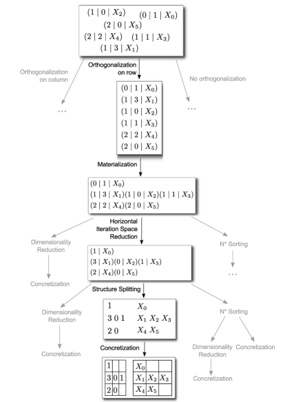
Figure 8 describes the whole process of generating a data storage format, starting from an unordered set of tuples and using several transformations of Section 4. Note that the resulting generated storage scheme is described in the literature as simplified Jagged Diagonal Storage, or ITPACK storage [2]. Important is that this storage format has been deduced without any predefinition of this format in the forelem framework. Rather, it has been derived with the described sequence of transformations.
In the figure, other transformations that can be applied are shown in gray. For example, when the structure splitting transformation in the figure is followed by dimensionality reduction, Compressed Row Storage (CSR) format is generated. Alternatively, a transformation sequence that continues from orthogonalization on column can result in Compressed Column Storage (CCS) format.
Let us consider a different application of the transformations. As a starting point, consider the data structure after application of Structure Splitting in the figure. First, sorting is applied, so that rows with similar number of entries (non-zeros) are placed close to each other. This can be helpful as a form of load balancing in the case of parallelization. Although this transformation changes the order in which the rows are processed, this does not introduce a problem because before the concretization the iteration of the rows is specified as a forelem loop which does not impose a particular execution order.
Secondly, the two-dimensional storage structure is put in column-major
order. This can be accomplished by using the Loop Interchange
transformation, as has been described earlier in this section. Thirdly, the
alternative form of materialization is applied. As a result, a
set PA_len is generated such that no zeros have to be inserted into
the data structure as padding. Through the application of dimensionality
reduction, the rows of the two-dimensional storage (which thus store columns
of the matrix) are stored back to back in a vector, without insertion of
padding zeroes. As a consequence, an additional data structure is added to
record the start of each row of the original two-dimensional structure.
This concretization leads to the Jagged Diagonal Storage format
described in the literature [2].
Note again that all data structures that come forth out of this automatic transformation process are basically the result of the application of some very basic transformations. For instance, ITPACK, Jagged Diagonal Storage and ELLPACK have been introduced in the literature as smart algorithmic solutions to optimize sparse matrix times vector computations. As a result of the transformations described in the preceding sections we can conclude that these supposedly smart implementations are nothing more than a succession of very simple basic transformations.
6.2.3 Generation of Hybrid Storage Formats
The derivations of sparse data storage formats that have been discussed so far do not include the loop blocking transformation. Similar to the well-known loop blocking compiler optimization transformation, loop blocking can also be applied to forelem loops resulting in a nested forelem loop in which the innermost loop iterates over a “block” of the sparse matrix. Then, by including the loop blocking transformation in the transformation chain, hybrid storage formats can be generated automatically. Given a loop nest that is orthogonalized for either the row or column direction, loop blocking will result in the matrix being processed in blocks of row or column vectors. When materialization is applied, for each of these blocks a different set of transformations could be carried out, leading to different storage formats. So, different hybrid storage formats can be generated by instantiating different combinations of the basic data structures that can be generated without loop blocking.
Further possibilities exist if a loop nest is orthogonalized for both the row and column directions. In this case, two additional outer loops are added during orthogonalization that control row and column iteration respectively, as can been seen in Figure 9 (top). When loop blocking is applied in this case, the matrix is processed by considering submatrices (blocks) of the matrix. For each submatrix, a storage format can be instantiated. The code fragment at the bottom of this figure shows the result of the application of the loop blocking transformation.
During Materialization, the three inner loops of this loop nest will be affected. This code will be transformed such that for each block (submatrix) that is iterated by the outer loops, a different code sequence carrying out the computation can be defined that operates on a different automatically generated data structure. The different data structures that are generated for these submatrices together form the hybrid data structure for the full matrix.
forelem (i; i ) forelem (j; j ) forelem (t; t T.(row,col)[(i,j)]) C[i] += B[t.col] * A[t];
forelem (ii; ii ) forelem (jj; jj ) forelem (i; i ) forelem (j; j ) forelem (t; t T.(row,col)[(i,j)]) C[i] += B[t.col] * A[t];
6.2.4 Automatic Data Partitioning and Distribution
In addition to the transformations that have been described in this paper, further advanced optimizations can be implemented within the forelem framework with ease. This includes transformations that can enable the framework to generate (distributed and parallel) data structures for multi-core and distributed execution of sparse matrix algebra. For instance, for parallel execution a sparse matrix is to be partitioned. This partitioning can be accomplished with the loop blocking transformation. Different methods for the partitioning and distribution of the matrix data can be implemented simply by introducing different methods for the partitioning of the iteration domain.
For example, Vastenhouw and Bisseling [22] describe a two-dimensional data distribution method for parallel sparse matrix-vector multiplication. This data distribution is derived by partitioning the nonzeros of the sparse matrix such that blocks arise with approximately similar amounts of nonzeros. In Figure 9, we showed a loop structure that gives rise to two-dimensional blocks of data. We defined these blocks to be regular in size. However, by simply redefinining the partitioning of and , we can automatically generate data structures and data distributions in which the matrix is partitioned into irregularly sized blocks, similar to that of Vastenhouw and Bisseling.
Many other methodologies for the distribution of data have been described in the literature that partition a matrix for efficient distributed processing or for more efficient use of the cache [5, 25, 24, 18]. In fact, all these distributions are the direct result of the application of the transformations described in this paper. Further, if we would generalize the orthogonalization transformation such that arbitrary subsets are selected in turn, then we would also be able to automatically generate complex, hybrid data structures, such as described in [12].
6.3 The Transformation Search Space
Using the approach described in the previous section, many different instantiations of the same sparse matrix routine can be generated. These different instantiations can be distinguished by the transformations that were performed before and/or after Materialization, and the order in which the transformations were performed. In fact, the myriad ways these transformations can be composed, and can be further combined with parametric compiler optimizations such as loop unrolling and loop blocking, yields a large search space. Getting to the code variant with optimal performance for a particular routine is the problem of finding a particular sequence of code transformations, or phases. This problem is known in the literature as the phase-ordering problem [20]. While this paper does not intend to solve the phase-ordering problem of which transformations to apply, we do discuss an initial exploration and characterization of this complicated search space, as it is extremely important to understand the characteristics of this search space before applying techniques to address the phase-ordering problem. In particular, this section section presents the results of the initial exploration of the search space of instantiations of sparse matrix times vectors multiplication.
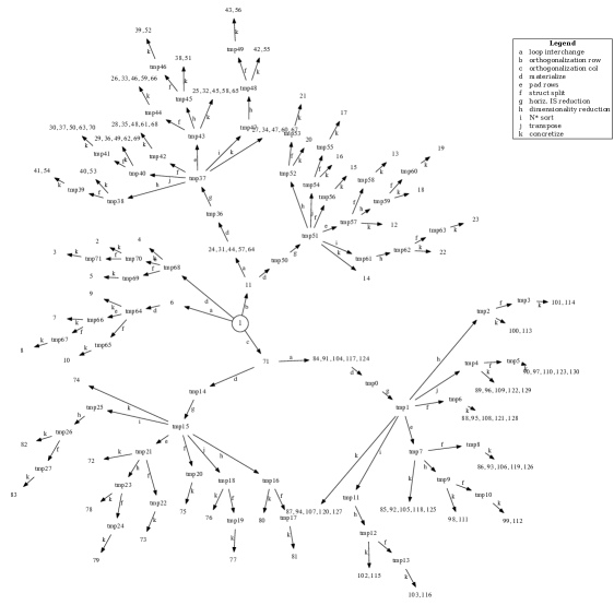
The full transformation tree of sparse matrix times vector multiplication is shown in Figure 10. The starting point of the transformation space is labeled with 1 and shown in the center of the figure. This is the minimal representation of the computation as a forelem loop. From this point, there are several different branches of transformations as shown in the picture, resulting in many different variants, or principal forms. Whenever the label of a node is prefixed with “tmp”, the node represents a stage for which no executable is generated. In all other cases, the executables (variants) are labeled from 1 to 130. Next to these 130 different implementations, also 25 different data structures are generated, ranging from simple coordinate storage to compressed row or column schemes, with or without zero-padded rows or columns, and jagged diagonal like schemes wherein the rows of the matrix have been permuted or not. This exemplifies the strength of our approach when compared to sparse algebra libraries, that on average implement 4, or less, pre-defined sparse data storage formats. Moreover, when combined with parametric compiler optimizations such as loop unrolling and loop blocking, the number of possible code variants is enlarged even further. In the next sections, we show that in this search space an automatically instantiated routine and corresponding data structure can be found that outperforms the implementations of existing sparse algebra libraries.
Finally, note that in this transformation tree we did not consider loop blocking. If loop blocking would have been taking into account, a multitude of different hybrid storage formats would have been generated, as has been illustrated in the previous section. For all these data structures, also corresponding initialization procedures are automatically generated.
6.4 Experimental Evaluation
To evaluate the effectiveness of the framework proposed in this paper, we compare the performance of the automatically generated variants to routines from three existing sparse algebra libraries. For three different sparse algebra kernels, we have generated all possible variants and executed these for 20 different sparse matrices. Subsequently, we have performed a number of different analysis to survey the best performing routines, the varying performance of library routines and to quantity overall library performance. The results show that variants generated with the framework proposed in this paper achieve significant reductions of the execution time compared to existing library implementations by up to 80.8%. Furthermore, we have found that none of the surveyed libraries performs consistently better than other libraries and that relying on a single library implementation never results in optimal performance across different input matrices. This reinforces the benefits of our approach which can automatically generate library routines specific for particular input matrices.
6.4.1 Experimental Setup
For the comparison of the automatically generated variants with sparse algebra libraries, three libraries and their associated data structures were used:
-
•
Blaze 1.2 [11], with the matrix stored in both row-major and column-major order;
-
•
MTL4 [10], with the matrix stored in both row-major and column-major order;
-
•
SparseLib++ 1.7 [9], with the matrix stored in coordinate storage format, compressed row storage format and compressed column storage format.
So, in total 7 different variants from 3 different libraries have been used in the experimentation. From these library routines three (shared) computational kernels were chosen:
-
•
sparse matrix times vector multiplication,
-
•
sparse matrix times matrix multiplication (with a -column dense matrix),
-
•
lower triangular solve with unit matrices.
The comparison with sparse matrix matrix multiplication from existing sparse algebra libraries has only been carried out with Blaze and MTL4, because SparseLib++ did not contain API for this computation. Similarly, the comparison with triangular solve was only done with the MTL4 and SparseLib++ libraries.
The experiments have been performed on two architectures. The first architecture consists of an Intel Xeon 5150 CPU at 2.66 Ghz, with 16GB RAM, running Ubuntu Linux 10.04.4. The second architecture is a machine that consists of an Intel Xeon E5-2650 CPU at 2.00 GHz, with 64 GB RAM, running CentOS 5.0. The compiler used in both cases is gcc 4.4. These architectures will be referred to as the Xeon 5150 and Xeon E5 architectures respectively. Twenty matrices have been surveyed, taken from the University of Florida Matrix Collection [7]. To remove fluctuation from the results, the computation performed by each variant or library is repeated 10 times.
| (a) Xeon 5150 | |||||||
|---|---|---|---|---|---|---|---|
| Blaze | MTL4 | SL++ | |||||
| CRS | CCS | CRS | CCS | COO | CRS | CCS | |
| \csvreader[late after line= | |||||||
| \csvcolxi (b) Xeon E5 | |||||||
| Blaze | MTL4 | SL++ | |||||
| CRS | CCS | CRS | CCS | COO | CRS | CCS | |
| \csvreader[late after line= | |||||||
| \csvcolxi | \csvcoliv | \csvcolv | \csvcolvi | \csvcolvii | \csvcolix | \csvcolx | |
6.4.2 Results
Experiments have been conducted with each of the above mentioned computational kernels. Each of these kernels has been run for each of the twenty matrices on both architectures. Note that our method relies on the fact that for each combination of matrix, kernel and architecture an optimized executable is automatically generated. The potential for performance optimization is demonstrated in this section by comparing each library routine with the best performing automatically generated kernel. The percentage reduction of the single-core execution time of the automatically generated variant over the library routines has been computed and is shown in the tables. In these tables, results printed on a black background indicate the largest reduction achieved by an automatically generated variant over a library routine. The results printed on a gray background indicate the minimum performance improvement that is realized, i.e., the automatically generated kernel is compared to the best performing routine with the best data structure selection.
Table 6.4.1(a) shows the comparison of the sparse matrix times vector multiplication kernel on the Xeon 5150 architecture. Improvements are achieved over all library kernels. The achieved reductions go up to 77.4% for the Erdos971 matrix using the MTL4 CCS routine. This means that the automatically generated variant runs in 22.6% of the execution time of the MTL4 CCS routine.
Instead of considering the library routines individually, the collection of library routines can be considered as a whole. Even if we take the fastest library routine for each matrix in this case, our method still achieves performance reductions of 37.1% (Erdos971), 31.7% (OPF_10000) and 30.9% (G2_circuit) for the Xeon 5150 architecture.
In Table 6.4.1(b) the results of the same kernel are shown for the Xeon E5 architecture. From the table can be seen that reductions of up to 70.7% (Erdos971 matrix, MTL4 CCS routine) are achieved. The performance reduction compared to the fastest library routine per matrix is still up to 46.6% (or2010).
| Xeon 5150 | Xeon E5 | |||||||
| Blaze | MTL4 | Blaze | MTL4 | |||||
| CRS | CCS | CRS | CCS | CRS | CCS | CRS | CCS | |
| \csvreader[late after line= | ||||||||
| \csvcolix | \csvcolii | \csvcoliii | \csvcoliv | \csvcolv | \csvcolvi | \csvcolvii | \csvcolviii | |
In Table 6.4.2 the percentage reduction of the single-core execution time of the sparse matrix times matrix kernel is presented for the libraries that implement this routine. Performance reductions are achieved of up to 79.0%. From the numbers on a gray background in this table can be seen that for both architectures variants are generated that decrease the execution time beyond 50% compared to the best-performing library routine for that matrix. The minimum reductions that are attained are significant: at least a 24.1% reduction for the Xeon 5150 architecture (consph matrix) and 12.4% for the Xeon E5 architecture (144 matrix).
| Xeon 5150 | Xeon E5 | |||||||
| MTL4 | SL++ | MTL4 | SL++ | |||||
| CRS | CCS | CRS | CCS | CRS | CCS | CRS | CCS | |
| \csvreader[late after line= | ||||||||
| \csvcolix | \csvcolii | \csvcoliii | \csvcoliv | \csvcolv | \csvcolvi | \csvcolvii | \csvcolviii | |
Finally, the results of the experiments with sparse triangular solve are shown in an identical manner in Table 6.4.2. For the Xeon 5150 architecture automatically generated routines are found that decrease the execution time by up to 80.1% and up to 80.8% for the Xeon E5. In most cases, an reduction of 10.4% to to 31.9% is achieved compared to the best-performing library routine. For four cases a slight decrease in performance is seen although still on par with the fastest library routine found. In case of the Xeon E5 architecture reductions of the computation time up to 44.7% are found. In the latter case also increases in computation time in almost half of the cases can be found. Note that these increases are mostly within 2 to 3 percent, so the performance in these cases can be considered on par with the library routines. The results for the triangular solve kernel are not as significant as for the other two computational kernels. This is caused by the fact that for this kernel the optimization possibilities are very limited because of the absences of data reuse in combination with data dependencies limiting execution reordering.
6.4.3 Varying Performance of Library Routines
From the presented results can also be observed that the performance results among the libraries vary. There is no library that performs consistently better than the other libraries for the surveyed kernels, matrices and architectures. For instance, while MTL4 performs better than Blaze on sparse matrix times matrix multiplication in half of the cases (Table 6.4.2), the same MTL4 library never outperforms SL++ on sparse triangular solve (Table 6.4.2). When considering the results for sparse matrix times vector multiplication in Table 6.4.1, Blaze outperforms other libraries on the Xeon E5 half of the time, while Blaze only achieves this twice on the Xeon 5150 architecture.
Also among the different data structures implemented by the libraries there is no data structure that is always better than others. As can be seen in Table 6.4.1(a) all data formats, CRS, CCS and coordinate storage, outperform all other data formats at least once. In Table 6.4.2 we observe that while SL++ CRS typically outperforms SL++ CCS, there is one case where SL++ CCS is faster. Also for the MTL4 library can be seen in the same table that the CCS data structure sometimes outperforms its CRS data structure.
Furthermore, if a library routine has the worst performance for a number of matrices, this does not mean that such a routine is never the best performer among library routines. In fact, whereas the SL++ COO routine is regularly the most distanced from the performance achieved by our generated variants, it is also in one case the least distanced.
The extent by which the performance of a library varies among different kernels, matrices and architectures is significant. For instance, from Table 6.4.1(a) can be seen that the generated variant for the blckhole matrix reduces the execution time by 20.9% compared to the Blaze CRS kernel. This is the minimum reduction that is achieved by our method, the realized reductions are larger compared to all other evaluated libraries. When the reduction of the execution time of just the Blaze CRS is considered over different matrices, then the measured performance improvements achieved by our method over this library routine go up to 52.7%. Note that for the several other matrices these achieved execution time reductions are smaller, for instance SL++ CRS outperforms the Blaze routines several times. Even compared between just these two library routines, the execution time of the Blaze routine can be reduced by up to 30.5% by the SL++ CRS routine in certain cases. This shows that when relying on a single library implementation, optimal performance is never achieved.
6.4.4 Quantifying Overall Performance Of Library Routines
The above examples make apparent that the performance of a particular routine varies when run for different matrices and on different architectures. Routines that are good performers for certain matrices, can be among the worst performers for other matrices. Within the approach proposed in this paper, many different variants are generated and these variants all exhibit different performance characteristics. As a consequence, in order to demonstrate the many advantages of this framework it is not sufficient to simply present the speedup of the best performing variant over an existing routine using an existing data structure. A variant that performs well for a certain matrix and architecture might be a bad performer for another combination.
In order to quantify these differences we use a coverage metric which essentially captures the percentage of matrices for which a single good performing routine can be found, given a certain percentage such a routine may be distanced from the optimal implementation. For example, if the coverage is less than 60%, then the found routine does not belong to the best performing routines for over 40% of the remaining matrices and consequently a different routine must be chosen for these matrices in order to obtain optimal performance. As another example, consider that a routine has been found with a 100% coverage and that routines may have been distanced up to 45% from the optimal implementation. Although a single routine has been found that is among the best performing for all matrices, this comes at the cost of performing 45% short of the optimal performance for certain matrices.
We now formally define this notion of coverage. Let be a set of routines, that can be library routines as well as variants generated using the framework described in this paper. is the set of all matrices surveyed in the experimentation. The measured execution time for a routine and a matrix is denoted . For a given matrix , one of the routines in will have the best execution time666Note that it is possible for the best execution time to be shared with more than 1 routine., this routine is referred to as . Now, a top group can be defined for a matrix that contains variants with a runtime at most away from the best variant :
Subsequently, the weight of a routine for a collection of matrices is defined that indicates the number of matrices of that collection for which the routine is a good performer:
Finally, the coverage is the maximal weight found among the set of routines for a collection of matrices:
Summarizing, in order to compute the coverage, a collection of matrices , set of routines and a percentage from the optimum for which variants are still considered to be among the best performing, are needed. The coverage indicates the maximal number of matrices for which a single routine is among the best performing routines. In other words, for how many matrices acceptable performance can be achieved with a single routine.
Note the effect of changing these parameters: if the percentage is increased, a larger set of routines is considered the best performing variants. As a result, the chances that a routine with a higher coverage is found are increased. However, as routines are allowed that are further distanced from the optimal implementation, overall performance of the routine might be worse! The best scenario is to find the maximal coverage for a value of which is as small as possible.
| Xeon 5150 | |||||
| t% | 10% | 20% | 30% | 40% | 50% |
| \csvreader[late after line= | |||||
| \csvcolvi | \csvcolii | \csvcoliii | \csvcoliv | \csvcolv | |
| Xeon E5 | ||||
|---|---|---|---|---|
| 10% | 20% | 30% | 40% | 50% |
| \csvreader[late after line= | ||||
| \csvcolvi | \csvcoliii | \csvcoliv | \csvcolv | |
Using this metric of coverage the differences in performance between different library routines are now evaluated. To this end, a collection has been formed of the kernels from the different libraries and the coverage was computed for increasing values of , see Table 6.4.4. From these results can be seen that the minimum value of that is necessary to find a single best-performing library routine, that is a library routine with a coverage of 100%, is significant. For instance, for sparse matrix times vector multiplication this is 43% for the Xeon 5150 and 21% for the Xeon E5 architectures. From these results follows that when relying on a single library implementation of a sparse matrix kernel to perform computations on different sparse matrices on different architectures, the optimal performance is never achieved. In fact, significant performance losses are incurred. The minimum values of also indicate the maximal performance loss that one has to accept in order to work with a single library routine. In case of the sparse matrix time vector multiplication, the performance thus falls short by as much as 43%.
The fact that for triangular solve the values of for a 100% coverage are below 100% correlates with the performance results seen in Table 6.4.2. For the Xeon E5 architecture is found, which indicates that it is possible to find a single best-performing library routine that fits all matrices in this case. This further confirms the fact that the optimization opportunities of the triangular solve kernel are very limited compared to the other computational kernels.
6.4.5 Optimization Of Computational Kernels Per Architecture
The performance of the collection of automatically generated kernels can also be compared with the performance of collections of routines from sparse algebra libraries using the coverage metric as defined in the previous subsection. In this case, the best routine found in the collection of automatically generated kernels and library routines combined is used as the optimal routine. The left graph in Figure 11 shows the result when this is done for the sparse matrix times vector kernel on the Xeon 5150 machine and the Blaze library. The x-axis shows the value that is considered, i.e., is the maximal percentage routines may be distanced from the optimal implementation. Smaller values of are closer to the performance of the optimal implementation.
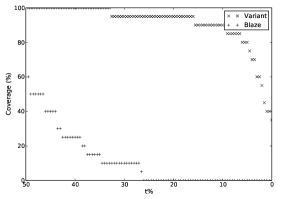
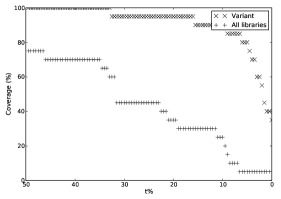
The coverage in percent can be read from the y-axis, which is the maximal number of matrices for which a variant is within the selected top group of implementations. From the figure can be deduced that no Blaze routine is found that is within 50% of the optimal implementation for all matrices. In fact, for values up to 26%, a routine from the Blaze library never makes it into the group of best performing variants for any matrix. This implies not only that the automatically generated kernels always outperform the Blaze library variants, but also that the automatically generated variants show a significantly better coverage potential.
The graph on the right in Figure 11 is a similar graph, but considers routines from all surveyed sparse algebra libraries instead of just Blaze. Although the collection of library routines fare better in this case, still for values of up to 7% the performance is fully dominated by the automatically generated variants. Furthermore, no single library routine can be found that has a performance within 50% of the optimal implementation for all matrices surveyed.
From this graph can also be seen that the automatically generated kernels persist a 100% coverage until a value of 34%, while the library routines do not achieve a 100% coverage within 50% of the optimal implementation. This indicates that for this particular architecture a kernel can be found that achieves a reasonable performance for all matrices, while still significantly outperforming library routines.
This leads us to the following technique to automatically and efficiently select an all round kernel for a particular architecture. For a small random selection of matrices, all variants are generated and run on the target architecture. Subsequently, for each of the matrices in the selection the optimal variant is determined. As a next step, a variant is chosen with an execution time that is a small, certain percentage from the optimum for all matrices in the selection. This kernel has a 100% coverage for the selection of matrices and will deliver reasonable performance for any other matrix.
| (a) | Xeon 5150 | Xeon E5 |
|---|---|---|
| SPMV | 23.7% | 19.8% |
| SPMM | 38.1% | 42.0% |
| TrSv | 11.2% | 3.1% |
| (b) | Xeon 5150 | Xeon E5 |
|---|---|---|
| SPMV | 9.1% | 9.5% |
| SPMM | 25.9% | 10.0% |
| TrSv | 13.1% | 11.0% |
To evaluate this technique, the average reduction of the execution time of the kernels found with the above described method and library routines is compared. The smaller this reduction of the execution time, the better performance a found kernel has. For each library routine the average reduction of the execution time has been computed and the minimum average reduction has been selected and shown in Table 5(a). As a demonstration of the above described method is chosen to obtain a representative selection of matrices and to select a top group of variants to consider. This results in a list of automatically generated kernels that are at most 2% from the optimal implementation for all of the selected matrices. For each of these kernels, the average reduction of execution time compared to the optimal kernel has been computed. The worst average found is shown in Table 5(b), so this is the worst kernel that would be selected by this method.
In the table can be seen for the sparse matrix times vector multiplication and sparse matrix times matrix kernels that the worst average reduction of the execution time of the automatically generated kernels is significantly smaller than the best average reduction of the execution time of library routines. For triangular solve, our techniques are on par for the Xeon 5150 architecture and slightly worse for the Xeon E5. As has been described above, the opportunities for optimization for the triangular solve kernel are small, leading to the worst average reduction of the execution time of automatically generated kernels to be larger than that of the library routine. However, if the average is considered of the kernels selected through this method, the performance is still on par with that of the library routine.
By employing this technique a specifically generated kernel can be selected automatically for a certain architecture by performing run-time tests with a small amount of matrices. This generated kernel outperforms existing library routines for all other matrices.
Note that our approach relies on finding the optimal performance of a kernel for a given matrix and architecture. The selection of such an optimal kernel is an expensive process requiring a vast search space of possible variants to be explored. However, in the method described above the optimization is only done once per architecture resulting in a significant reduction of the optimization overhead while yielding a version of each kernel which performs substantially better than current approaches, i.e., optimized hand-written codes optimized with standard compiler optimizations.
7 Related Work
Bik and Wijshoff described compiler techniques to automatically generate an implementation of a computation that operates on sparse matrix structures from an implementation of that computation expressed in terms of dense matrices that is supplied to the compiler [3, 4]. User annotations about matrix statistics (e.g. its sparsity) or interactive user input is used to aid the compiler in selecting an efficient, pre-defined, sparse storage format for the matrices used in the computation. A major difference between the work of Bik and Wijshoff and this paper is that in the case of Bik and Wijshoff a data structure is selected from a pre-defined set of data structures, whereas in this paper we propose techniques for the automatic generation of data structures. The generation procedure does not depend on any collection of pre-defined structures or templates.
Mateev et al. proposed a generic programming methodology to bridge the gap between algorithm implementation API and storage format API [16]. Algorithms are implemented as generic dense matrix programs, without considering a particular data storage format. The details of different, pre-defined, data structure formats are exposed using a low-level API. Their framework views sparse matrix formats are indexed-sequential access data structures and uses a restructuring technology based on relational algebra to convert a high-level algorithm into a data-centric implementation that exploits characteristics of the available sparse formats whenever possible. Matrices are considered as collections of tuples for the purpose of restructuring towards an existing sparse storage format.
Note that both approaches only restructure towards existing, pre-defined formats and are not capable of automatically generating a data storage format like is accomplished by the approach described in this paper.
Marker et al. described a method for the automatic parallelization and optimization of Dense Linear Algebra for distributed-memory computers called Design by Transformation (DxT) [15]. Their method works by modeling algorithms in a data-flow graph. The graph contains nodes that represent redistribution operations or a LAPACK or BLAS function call. Optimization is carried out by applying graph transformations to find equivalent graphs that potentially exhibit better performance.
OSKI is a library capable of automatically tuning sparse matrix kernels for a particular matrix and machine [23]. The library uses run-time information to select a data structure and particular implementation of a kernel that provides improved performance. Contrary to our approach, OSKI is restricted to a pre-defined set of routines and a pre-defined set of data structures to tune to. Although this pre-defined set of routines can be partially generated automatically, the pre-defined set of data structures is not, as OSKI is not capable of generating new data structures automatically like is possible with the framework described in this paper.
Structure splitting is a compiler optimization that transforms an array of structures into a structure of arrays [6]. Whereas this can be seen as an optimization that modifies how the data is stored, the essence of the specified data structure remains the same and the way the data is organized is not substantially modified. Tuple splitting is only one of the transformation steps in our framework, making the forelem framework far more versatile. Similarly, initial work has been done on run-time restructuring and linearization [21]. These techniques trace memory accesses at run-time and subsequently permute the data and/or transform linked lists to arrays, to attempt to eliminate random memory accesses. By doing so, the data is permuted to suit the iteration pattern, or control flow, as has been specified in the program. Although the order in which data is stored is addressed, also in this case the way how data is organized, or grouped, is not changed. A linked list of entities is transformed to an array of entities, but the definition of what makes up this entity is unchanged. So, while these techniques do effectively improve the performance of certain applications, there is room for much more.
8 Conclusions and Future Work
We have introduced a compiler-based framework to enable the automatic generation of data structures. To do so, a different scheme to specify programs is proposed, in which the specification of fixed iteration orders and data structures is avoided. As a result, the compiler can go beyond the optimization of solely control flow and target the way data is organized and accessed as well. This is achieved using a collection of transformations, defined with the forelem framework, that target both the loop structure of the computation as well as the data layout that the code operates on.
We demonstrated the power of this framework with a case study on the automatic generation of sparse data structures for sparse matrix routines. Many different variants of a given (sparse matrix) computation can be instantiated automatically, where an efficient code routine is combined with the reassembly of the original sparse matrix data structure into a form that is better aligned with the computation that is performed. All data structures that come forth out of the automatic transformation process described in this paper are basically the result of the application of a number of very simple transformations. This includes data structures such as ITPACK and Jagged Diagonal Storage that have been introduced in the literature [13, 2] as smart algorithmic solutions to optimize sparse matrix times vector computations. Consequently, we can conclude that these supposedly smart implementations are nothing more than a succession of very simple basic transformations.
Furthermore, when loop blocking is considered, a multitude of different hybrid storage schemes can be generated automatically that could impossibly be pre-defined in a sparse data structure library. Loop blocking is also the main enabling transformation for the automatic generation of data distributions for distributed sparse computations. So, with the transformations described in this paper, it is not only possible to generate efficient data structures for sparse matrix computations that are executed on a single processor core, but also to generate efficient data distributions for distributed sparse computations automatically.
The transformations that enable the generation of sparse data structures to be automated set up a large transformation search space, leading to much wider optimization opportunities. This search space can be further extended with parametric optimizations such as loop unrolling. We have shown that within this search space, variants of the computation can be found that are faster than the implementations found in existing sparse algebra libraries. Additionally, we have shown none of the surveyed existing libraries to perform consistently better. So, by relying on a single library implementation performance is never optimal. This further reinforces our approach to give the compiler control over data structure optimization and to tailor data structures to input data.
Based on the framework presented in this paper, there are many avenues for future work. Case studies will be done for other application domains of these techniques, such as graph data structures, databases and multi-dimensional storage. This will likely also lead to more generic transformations to be included in the framework. In particular for multi-dimensional storage, it is interesting to investigate the possibilities and benefits of automatically generating hybrid data structures. Finally, techniques need to be researched to effectively navigate the search space of possible variants in search of the optimal routine and to solve the phase ordering problem of the available transformations.
References
- [1] John R Allen and Ken Kennedy. Automatic loop interchange. In ACM SIGPLAN Notices, volume 19, pages 233–246. ACM, 1984.
- [2] Zhaojun Bai, James Demmel, Jack Dongarra, Axel Ruhe, and Henk van der Vorst, editors. Templates for the Solution of Algebraic Eigenvalue Problems. Society for Industrial and Applied Mathematics, 2000.
- [3] Aart J. C. Bik and Harry A. G. Wijshoff. Compilation techniques for sparse matrix computations. In Proceedings of the 7th international conference on Supercomputing, pages 416–424. ACM, 1993.
- [4] Aart J. C. Bik and Harry A. G. Wijshoff. Automatic data structure selection and transformation for sparse matrix computations. Parallel and Distributed Systems, IEEE Transactions on, 7(2):109–126, 1996.
- [5] Umit V Catalyurek and Cevdet Aykanat. Hypergraph-partitioning-based decomposition for parallel sparse-matrix vector multiplication. Parallel and Distributed Systems, IEEE Transactions on, 10(7):673–693, 1999.
- [6] Stephen Curial, Peng Zhao, Jose Nelson Amaral, Yaoqing Gao, Shimin Cui, Raul Silvera, and Roch Archambault. MPADS: memory-pooling-assisted data splitting. In ISMM ’08: Proceedings of the 7th international symposium on Memory management, pages 101–110, New York, NY, USA, 2008. ACM.
- [7] Timothy A Davis and Yifan Hu. The university of florida sparse matrix collection. ACM Transactions on Mathematical Software (TOMS), 38(1):1, 2011.
- [8] J. B. Dennis, J. B. Fosseen, and J. P. Linderman. Data flow schemas. In Andrei Ershov and Valery A. Nepomniaschy, editors, International Symposium on Theoretical Programming, pages 187–216, Berlin, Heidelberg, 1974. Springer Berlin Heidelberg.
- [9] Jack Dongarra, Andrew Lumsdaine, Xinhiu Niu, Roldan Pozo, and Karin Remington. A sparse matrix library in c++ for high performance architectures. 1994.
- [10] Peter Gottschling, David S Wise, and Michael D Adams. Representation-transparent matrix algorithms with scalable performance. In Proceedings of the 21st annual international conference on Supercomputing, pages 116–125. ACM, 2007.
- [11] Klaus Iglberger, Georg Hager, Jan Treibig, and Ulrich Rude. High performance smart expression template math libraries. In High Performance Computing and Simulation (HPCS), pages 367–373. IEEE, 2012.
- [12] Vasileios Karakasis, Theodoros Gkountouvas, Kornilios Kourtis, Georgios Goumas, and Nectarios Koziris. An Extended Compression Format for the Optimization of Sparse Matrix-Vector Multiplication. Parallel and Distributed Systems, IEEE Transactions on, 24(10):1930–1940, 2013.
- [13] D. Kincaid, T. Oppe, and D. Young. Vector computations for sparse linear systems. SIAM Journal on Algebraic Discrete Methods, 7(1):99–112, 1986.
- [14] D. Lehmann, A. Pnueli, and J. Stavi. Impartiality, justice and fairness: The ethics of concurrent termination. In Proc. Automata, Languages and Programming (Lecture Notes in Computer Science), volume 115, 1981.
- [15] Bryan Marker, Jack Poulson, Don Batory, and Robert Geijn. Designing linear algebra algorithms by transformation: Mechanizing the expert developer. In High Performance Computing for Computational Science - VECPAR 2012, volume 7851 of Lecture Notes in Computer Science, pages 362–378. Springer Berlin Heidelberg, 2013.
- [16] Nikolay Mateev, Keshav Pingali, Paul Stodghill, and Vladimir Kotlyar. Next-generation generic programming and its application to sparse matrix computations. In Proceedings of the 14th international conference on Supercomputing, pages 88–99. ACM, 2000.
- [17] Padua, David A. and Wolfe, Michael J. Advanced compiler optimizations for supercomputers. Commun. ACM, 29(12):1184–1201, December 1986.
- [18] Ali Pinar and Michael T Heath. Improving performance of sparse matrix-vector multiplication. In Proceedings of the 1999 ACM/IEEE conference on Supercomputing (CDROM), page 30. ACM, 1999.
- [19] Kristian F. D. Rietveld and Harry A. G. Wijshoff. Forelem: A Versatile Optimization Framework For Tuple-Based Computations. In CPC 2013: 17th Workshop on Compilers for Parallel Computing, July 2013.
- [20] Sid-Ahmed-Ali Touati and Denis Barthou. On the decidability of phase ordering problem in optimizing compilation. In Proceedings of the 3rd conference on Computing frontiers, pages 147–156. ACM, 2006.
- [21] H. L. A. van der Spek, S. Groot, E. M. Bakker, and H. A. G. Wijshoff. A compile/run-time environment for the automatic transformation of linked list data structures. Int. J. Parallel Program., 36(6):592–623, December 2008.
- [22] Brendan Vastenhouw and Rob H Bisseling. A two-dimensional data distribution method for parallel sparse matrix-vector multiplication. SIAM review, 47(1):67–95, 2005.
- [23] Richard Vuduc, James W Demmel, and Katherine A Yelick. OSKI: A library of automatically tuned sparse matrix kernels. In Journal of Physics: Conference Series, volume 16, page 521. IOP Publishing, 2005.
- [24] Richard W Vuduc and Hyun-Jin Moon. Fast sparse matrix-vector multiplication by exploiting variable block structure. In High Performance Computing and Communications, pages 807–816. Springer, 2005.
- [25] AN Yzelman and Rob H Bisseling. Cache-oblivious sparse matrix-vector multiplication by using sparse matrix partitioning methods. SIAM Journal on Scientific Computing, 31(4):3128–3154, 2009.