Dewetting dynamics of sheared thin polymer films: an experimental study 111This document is the unedited Author’s version of a Submitted Work that was subsequently accepted for publication in ACS Macro Letters, copyright © 2022 American Chemical Society after peer review. To access the final edited and published work see https://doi.org/10.1021/acsmacrolett.2c00070
Abstract
An experimental investigation is reported on the effect of shear on the bursting of molten ultra-thin polymer films embedded in an immiscible matrix. By using an optical microscope coupled with a shearing hotstage, the dewetting dynamics, i.e. the growth of dewetting holes is monitored over time at various shear rates. It is observed that their circularity is modified by shear and that for all temperatures and thicknesses studied, the growth speed of the formed holes rapidly increases with increasing shear rate. A model balancing capillary forces and viscous dissipation while taking into account shear-thinning is then proposed and captures the main features of the experimental data, such as the ellipsoid shape of the holes and the faster dynamics in the direction parallel to the shear. This research will help to understand the instabilities occurring during processing of layered polymeric structures, such as multilayer coextrusion.
keywords:
thin films, polymer films, dewetting, shearPIMM]Laboratoire PIMM, CNRS, Arts et Métiers Institute of Technology, Cnam, HESAM Université, 75013 Paris, France PIMM]Laboratoire PIMM, CNRS, Arts et Métiers Institute of Technology, Cnam, HESAM Université, 75013 Paris, France PIMM]Laboratoire PIMM, CNRS, Arts et Métiers Institute of Technology, Cnam, HESAM Université, 75013 Paris, France PIMM]Laboratoire PIMM, CNRS, Arts et Métiers Institute of Technology, Cnam, HESAM Université, 75013 Paris, France
![[Uncaptioned image]](/html/2203.06727/assets/Figures/graphical_abstract.png)
1
Rupture of thin liquid films, whether free or supported on a solid or liquid substrate, has long been studied 1, 2, 3. It can be attributed to the amplification of thermal fluctuations at the interface by long-range interactions or to the nucleation and growth of dry patches, leading to the formation of holes in the film 4, 5, 6, 7. In the supported case, while retracting, the film generally pushes material into a rim around the hole which grows due to surface tension, until the rims coalesce to form droplets. The speed at which the holes grow (i.e. dewetting speed) results from an equilibrium between surface tension that draws the rim and viscous dissipation, and depends on the nature of the substrate and the viscosity of the film.
Similar mechanisms occur in ultra-thin polymer films (thicknesses well-below 1 m) when heated above their glass transition (or melting) temperature. They also have been thoroughly examined both from a theoretical and experimental point of view 8, 9, 10, 11, 12. The effects of viscoelasticity 13, slip 14 or residual stresses 15 have been considered, as such films find many industrial applications in conformal, protective, optical or functional coatings16, 17, 18, 19 and electrical films 20.
A case less studied is the stability of multilayer structures, i.e. stratified thin liquid (or polymeric) films of different nature 21. They can be found in microfluidic applications 22, packaging applications23 or used for the fabrication of functionalized fibers 24, and obtained through lithographic printing process 22, thermal drawing 24, layer-by-layer deposition 25, or multilayer coextrusion 26.
Theoretical and numerical studies have evaluated the effect of thicknesses and viscosities in the modes of rupture in confined multilayers 22, 27. In recent works, aiming to elucidate the physical mechanisms responsible for layer break-ups during multilayer coextrusion 28, 29, we developed an experimental set-up to analyze the dewetting speed in a confined trilayer 30, 31.
This consisted of an ultra-thin ( nm) polystyrene (PS) layer in between two micrometric poly(methyl methacrylate) (PMMA) layers. Basically, the holes’ growth speed, , can be described as the bursting of a Newtonian fluid film in a viscous environment 32 with dissipation occurring not in the PS film but in the surrounding PMMA. In this case , where is the PS/PMMA interfacial tension, and the Newtonian PMMA viscosity.
Another barely studied question of interest is the role of shear on the dewetting. Shear is indeed applied in most of the processes used to produce these stratified structures, and understanding its effect on the stability and dewetting dynamics is then of fundamental importance. Numerical works in a bilayer flow 33, for a thin liquid film 34 or an ultra-thin polymer film 35 have shown that shear can delay or, above a critical shear rate, even suppress the rupture. From an experimental point of view, to the best of our knowledge, only two qualitative studies were conducted on sheared trilayer systems, but were mostly focused on the observation of the appearance of the holes 36, 37.
Since it appears no work aims at elucidating the role of shear in the evolution of the dewetting dynamics, we propose here such quantitative study in a PMMA/PS/PMMA trilayer.
First, the morphology of the holes varies significantly with shear rate, from a round shape at rest to an elongated (ellipsoid) one in the shear direction (see Figure 1), with an effect more pronounced as shear increases. Note that the shape of the rim also seems altered, with most of its volume gathered around the vertices of the holes instead of a regular shape around the hole. A similar change in the shape of the hole was also noticed in the case of PS dewetting from a stretched elastomer substrate38.
We can describe the steady-state hole’s growth speed without shear (i.e. when the hole is circular) based on our previous studies 30, 31. It is defined as , where is the radius of the hole and the time of the experiment. We assume that after a transient regime leading to the formation of a toroidal rim, the PS initially contained in the hole’s volume is gathered into it39.
The change of capillary energy may then be written as:
| (1) |
where is the PMMA/PS interfacial tension in J/m2 determined using Wu’s empirical equation40 with the temperature in °C.
In the present study, since , confinement effects on the dewetting dynamics can be neglected 31 and in this range of viscosity ratio , the dissipation shall occur within the surrounding PMMA 31, 30. Consequently, the dissipated power can be set up as:
| (2) |
where is the PMMA Newtonian viscosity at the study temperature determined from the Carreau-Yasuda model (see Experimental Section) and is the radius of the rim’s cross-section.
Balancing equations (1) and (2), a constant growth speed is obtained in the case of dewetting without external shear:
| (3) |
where is a numerical prefactor of order unity due to geometric simplifications from the scaling approach. For the five configurations () tested, we obtain .
As a first simple comparison with the case without shear, we define an effective radius for the sheared ellipsoidal holes, such as , where is the semi-major axis and the semi-minor axis of the ellipsoid. At a given shear rate, monitoring the evolution of over time leads to the average growth speed , similar to the previous approach (see Figure 2). increases sharply with increasing shear rate, for all tested conditions. Temperature variation has a bigger effect on the dynamics than changing the PS thickness, suggesting that viscosity still plays a major role on the dewetting. The increase of is most pronounced at 200°C, from about 100 nm/s without shear to 400 nm/s at shear rate 1.6 s-1.
Considering the effect of shear on both the increasing average growth speed of the holes and the differences in their morphology, we now try to go further and propose a model describing these observations. In the following, a more quantitative approach will consist in evaluating separately the growth speed in the shear direction, , and perpendicular to shear, , from the temporal evolution of and respectively.
The obtained results are plotted as a function of shear rate in Figure 3. Undoubtedly, for a given shear rate, is smaller than and its increase with increasing shear is slower. Typically increased by a factor 2 from 0 to 1.6 s-1, while the increase for in the same interval is 5 to 8 times.
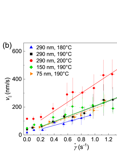
In the direction perpendicular to the applied shear, we first make the hypothesis that the growth speed can be described by the no-shear model (see Eq. 3), i.e. dewetting dynamics is only affected by shear parallel to the movement direction. However, we still must consider that PMMA displays shear-thinning behavior in the molten state, like most thermoplastics.
Hence the applied shear may modify its viscosity and consequently the dissipation in the vicinity of the rim.
We can then use the Carreau-Yasuda equation (see Experimental Section) to modify Eq. 3 into:
| (4) |
Using the parameters obtained from the rheological measurements for PMMA (see Table 1), the best fits with only as a fitting parameter are presented in Figure 3a. Though the data are somewhat scattered, the model captures reasonably well the trends for all conditions. Especially, at all temperatures the slight increase in growth speed with increasing shear rate can be described by the PMMA shear-thinning. Another experimental observation confirmed by the analytical model is that does not seem to depend on the initial PS film thickness (see green, orange and black points). Finally, all the values obtained for are close to each other, , in excellent agreement with obtained without shear.
Let us now move to the growth speed along the applied shear direction . In this case there is a need to incorporate an additional term taking into account the external shear applied when balancing dissipated viscous power and the capillary energy changes:
| (5) |
where is, same as for , a function of .
Reintroducing and another geometric constant for the term describing external shear, this leads to a solution of the form:
| (6) |
Here we can define a critical shear rate, , such as:
| (7) |
Through factoring and expanding the square root we simplify the solution by identifying two regimes for :
| (8) |
To estimate the rim size, we use volume conservation and for the sake of simplicity will assume a toroidal shape. We also use an average value for the effective radius at a given set of parameters (). With these hypotheses, we can write . 31 It has been verified indeed does not vary much from hole to hole nor during the limited experimental time nor with different shear rates (i.e. the morphology of the holes changes but their area does not). Coming back to Eq. 7, we obtain s-1 for all the systems studied. In Figure 3b, we then use the equation from the second regime to fit the experimental data for s-1, with only as a fitting parameter. The model predicts well the growth speed evolution with shear rate for every condition studied. The obtained values for are slightly scattered, , while a constant value, similarly to , shall be expected. Still, the variations do not seem to follow a monotonic trend with either PS thickness or PMMA viscosity, and may then be due to the simplifying hypotheses to estimate .
To further examine the validity of our model, we conclude by analyzing the ratio as a function of the applied shear. The results are plotted in Figure 4. Starting from a circular shape without shear (i.e. ), the holes deform more and more as shear is applied (see also Figure 1). Hence increases for all temperatures and all PS thicknesses, up to a value close to 3 for shear rates of 1.6 s-1. Considering that this ratio should be equal to /, the previous model can be used to describe it, following Eq. 9:
| (9) |
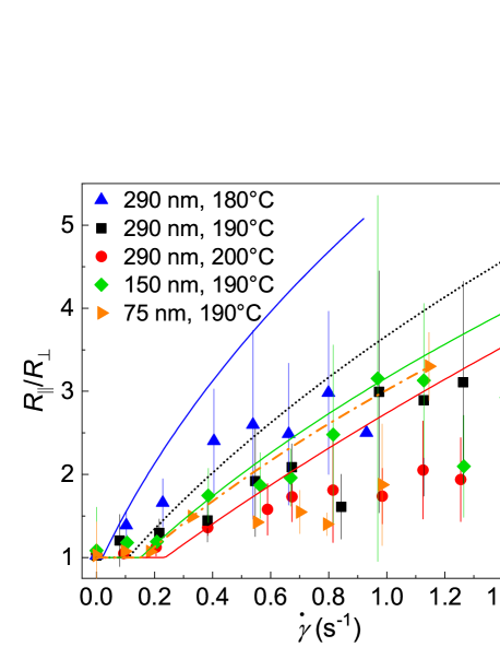
Figure 4 shows the corresponding fits with the previously obtained values for and , i.e. without new adjusting parameters. The model captures semi-quantitatively the data, especially small changes at low shear rates, as well as the sharp increase at higher ones. More specifically, experimental trends such as a higher ratio for higher PMMA viscosities or thicker PS films, are also well-described.
However, a slight overestimate of the predicted holes’ elongation is observed in every cases. This could be due to the fact that shear plays a bigger role than only shear-thinning of the surrounding matrix in the dewetting dynamics perpendicular to it (see also Figure 3a).
In conclusion, the quantification of dewetting dynamics of ultra-thin polymer films under shear was achieved for the first time, and reported for different temperatures and film thicknesses. Though shear can delay rupture 35, 34, once holes are created they grow faster with increasing shear. This was described satisfactorily by a simple analytical model balancing interfacial tension with the viscous dissipation occurring in the matrix, due to the rim’s movement and the external shear applied. The model, assuming that shear does not affect the growth speed perpendicularly to the movement but only in the direction parallel to it, captures the experimentally obtained data. This study shall give insight to the instabilities happening during processes allowing the fabrication of such layered structures, such as multilayer coextrusion. Future work will aim at refining the proposed model. Especially, from a theoretical point of view we shall consider more precisely the effect of shear in the perpendicular direction, polymer-polymer interfacial slip, and focus experimentally on capturing more precisely the onset of dewetting as well as the shape of the rim. A set-up allowing to work at higher shear rates will also be of interest.
2 Experimental Section
Following our previous works 31, 30, 28, commercially available grades of PS and PMMA, namely PS 1340 (Total) and PMMA VM100 (Arkema), were selected for the study. The molecular weights and glass transition temperatures have been measured before 28, 30.
The viscoelastic properties of the polymers have been measured at three temperatures (180, 190 and 200°C) with a DHR 20 (TA Instruments) rheometer with a plate-plate geometry (25 mm diameter and 1 mm gap) under air flow. The experiments were performed on PS pellets and PMMA films samples with a similar thermal history to the trilayers. Frequency sweep tests were conducted in the range from 0.045 to 628 rad/s with an applied strain of 1%, in the linear viscoelasticity region. The zero-shear viscosity (), relaxation time (), and shear-thinning exponents ( and ) were obtained for the two polymers at three temperatures using the classical Carreau-Yasuda model (see Eq. 10): 41, 42
| (10) |
with the complex viscosity and the angular frequency in rad/s.
The obtained parameters are displayed in Table 1 and show that PS and PMMA have a similar shear-thinning behavior. The analysis of the dewetting data was conducted assuming the classical Cox-Merz rule 43: .
| (°C) | (Pas) | (s) | |||
| PS | 180 | 58400 | 2.96 | 0.91∗ | 0.37∗ |
| 190 | 29200 | 1.48 | |||
| 200 | 14600 | 0.74 | |||
| PMMA | 180 | 52800 | 0.91 | 0.75∗ | 0.34∗ |
| 190 | 29200 | 0.43 | |||
| 200 | 13100 | 0.15 | |||
| ∗ average values with standard deviations smaller than 0.01 | |||||
PS thin films were prepared via spin-coating (Spin 150 v-3, SPS) PS in toluene (99.8%, VWR) solutions onto a silicon wafer (100 crystal orientation, Sil’tronix) at 2000 rpm/s and 2000 rpm/s2 for 60 s. Three previously filtered concentrations (1.5, 2.5, and 4.0 wt.%) were used. Films with thicknesses nm, 150 10 nm, and 290 15 nm were obtained and controlled for each sample by AFM (Nanoscope V, Veeco) in tapping mode.
PMMA films were prepared by thermopressing pellets between two glass slides at 200°C in a laboratory press (Gibitre Instruments). Films with thicknesses from 70 to 170 m were obtained, as determined by a digital length gauge system with accuracy of 0.2 m (Heidenhain). The root mean square roughness values obtained by AFM was below 10 nm, in all cases considerably smaller than the PS thickness. Any possible impact of this roughness on the dewetting dynamics was neglected herein.
The PMMA films were sorted into pairs of similar thicknesses to ensure symmetric trilayers. The PS films were cut into small pieces (about mm) and floated in a distilled water bath. A piece of PS film was then moved onto the PMMA substrate. The bilayer was left to dry at room temperature for about 12 h. Afterwards, the second PMMA film was placed on top. Such trilayer samples were kept in an oven at 60°C before the experiments to prevent water uptake.
Shearing experiments were conducted in a shearing hotstage (CSS450, Linkam Scientific Instruments) placed under an optical microscope (Eclipse LV150N, Nikon). The trilayer samples were placed on a quartz glass in the cell and pre-heated at 160°C for 3 minutes. Next, the gap, , was set to 97.5% of the trilayer’s initial thickness and kept for another 3 minutes to ensure proper adhesion. Afterwards, the temperature was increased to the temperature of the measurement and the sample subjected to a chosen shear rate. Due to the limited observation window of the microscope and the movements induced by shear, this study only deals with s-1. Such shear rates are nonetheless consistent with those typically achieved during multilayer coextrusion 28, 44.
The authors thank Joshua McGraw and Frederic Restagno for fruitful discussions and critical reading of the manuscript. The Ecole Doctorale SMI (ED 432) is acknowledged for granting A.D. the fellowship for her PhD work.
References
- Vrij 1966 Vrij, A. Possible Mechanism for the Spontaneous rupture of thin Free Liquid Films. Discuss. Faraday Soc. 1966, 42, 23–33, DOI: 10.1039/DF9664200023
- Sheludko 1967 Sheludko, A. Thin liquid films. Adv. Colloid Interface Sci. 1967, 1, 391–464, DOI: 10.1016/0001-8686(67)85001-2
- Ruckenstein and Jain 1974 Ruckenstein, E.; Jain, R. Spontaneous Rupture of Thin Liquid Films. J. Chem. Soc. Faraday Trans. 1974, 70, 132–147, DOI: 10.1039/F29747000132
- Oron et al. 1997 Oron, A.; Davis, S. H.; Bankoff, S. G. Long-scale evolution of thin liquid films. Rev. Mod. Phys. 1997, 69, 931–980, DOI: 10.1103/RevModPhys.69.931
- Craster and Matar 2009 Craster, R. V.; Matar, O. K. Dynamics and stability of thin liquid films. Rev. Mod. Phys. 2009, 81, 1131–1198, DOI: 10.1103/RevModPhys.81.1131
- Moreno-Boza et al. 2020 Moreno-Boza, D.; Martinez-Calvo, A.; Sevilla, A. Stokes theory of thin-film rupture. Phys. Rev. Fluids 2020, 5, 014002, DOI: 10.1103/PhysRevFluids.5.014002
- Kheshgi and Scriven 1991 Kheshgi, H. S.; Scriven, L. Dewetting: Nucleation and growth of dry regions. Chem. Eng. Sci. 1991, 46, 519–526, DOI: 10.1016/0009-2509(91)80012-N
- Krausch 1997 Krausch, G. Dewetting at the interface between two immiscible polymers. J. Phys.: Condens. Matter. 1997, 9, 7741–7752, DOI: 10.1088/0953-8984/9/37/007
- Brochard Wyart et al. 1993 Brochard Wyart, F.; Martin, P.; Redon, C. Liquid/Liquid Dewetting. Langmuir 1993, 9, 3682–3690, DOI: 10.1021/la00036a053
- Qu et al. 1997 Qu, S.; Clarke, C. J.; Liu, Y.; Rafailovich, M. H.; Sokolov, J.; Phelan, K. C.; Krausch, G. Dewetting Dynamics at a Polymer-Polymer Interface. Macromolecules 1997, 30, 3640–3645, DOI: 10.1021/MA961297H
- Reiter 1992 Reiter, G. Dewetting of thin polymer films. Phys. Rev. Lett. 1992, 68, 75–78, DOI: 10.1103/PhysRevLett.68.75
- Vilmin and Raphaël 2006 Vilmin, T.; Raphaël, E. Dewetting of thin polymer films. Eur. Phys. J. E 2006, 21, 161––174, DOI: 10.1140/epje/i2006-10057-5
- Mulama et al. 2019 Mulama, A.; Chandran, S.; Roumpos, K.; Oduor, A.; G., R. Dewetting Rheology for Determining Viscoelastic Properties of Nonequilibrated Thin Polymer Films. Macromolecules 2019, 52, 7894–7903, DOI: 10.1021/acs.macromol.9b01384
- Peschka et al. 2019 Peschka, D.; S., H.; Marquant, L.; Jacobs, K.; Münch, A.; Wagner, B. Signatures of slip in dewetting polymer films. PNAS 2019, 116, 9275–9284, DOI: 10.1073/pnas.1820487116
- Reiter et al. 2005 Reiter, G.; Hamieh, M.; Damman, P.; Sclavons, S.; Gabriele, S.; Vilmin, T.; Raphaël, E. Residual stresses in thin polymer films cause rupture and dominate early stages of dewetting. Nature Mater. 2005, 4, 754–758, DOI: 10.1038/nmat1484
- Krogman et al. 2005 Krogman, K. C.; Druffel, T.; Sunkara, M. K. Anti-reflective optical coatings incorporating nanoparticles. Nanotechnology 2005, 16, S338–S343, DOI: 10.1088/0957-4484/16/7/005
- Katsumata et al. 2018 Katsumata, R.; Limary, R.; Zhang, Y.; Popere, B. C.; T., H. A.; Li, M.; Trefonas, P.; Segalman, R. A. Mussel-Inspired Strategy for Stabilizing Ultrathin Polymer Films and Its Application to Spin-On Doping of Semiconductors. Chem. Mater. 2018, 30, 5285–5292, DOI: 10.1021/acs.chemmater.8b02027
- Runser et al. 2019 Runser, R.; Root, S. E.; Ober, D. E.; Choudhary, K.; Chen, A. X.; X., D. A.; Urbina, A. D.; Lipomi, D. J. Interfacial Drawing: Roll-to-Roll Coating of Semiconducting Polymer and Barrier Films onto Plastic Foils and Textiles. Chem. Mater. 2019, 31, 9078–9086, DOI: 10.1021/acs.chemmater.9b03343
- Lynge et al. 2011 Lynge, M. E.; Ogaki, R.; Overgard Laursen, A.; Lovmand, J.; Sutherland, D. S.; Städler, B. Polydopamine/Liposome Coatings and Their Interaction with Myoblast Cells. ACS Appl. Mater. Interfaces 2011, 3, 2142–2147, DOI: 10.1021/am200358p
- Shi 1996 Shi, F. F. Recent advances in polymer thin films prepared by plasma polymerization. Synthesis, structural characterization, properties and applications. Surf. Coat. Technol. 1996, 82, 1–15, DOI: 10.1016/0257-8972(95)02621-5
- Bertin et al. 2021 Bertin, V.; Carmen, L. L.; Salez, T.; Raphael, E.; Dalnoki-Veress, K. Capillary levelling of immiscible bilayer films. J. Fluid Mech. 2021, 911, DOI: 10.1017/jfm.2020.1045
- Lenz and Kumar 2007 Lenz, R. D.; Kumar, S. Instability of confined thin liquid film trilayers. J. Colloid Interface Sci. 2007, 316, 660–670, DOI: 10.1016/j.jcis.2007.08.009
- Langhe and Ponting 2016 Langhe, D.; Ponting, M. Manufacturing and novel applications of multilayer polymer films; William Andrew, 2016
- Nguyen-Dang et al. 2017 Nguyen-Dang, T.; de Luca, A.; Yan, W.; Qu, Y.; Page, A.; Volpi, M.; Das Gupta, T.; Lacour, S.; Sorin, F. Controlled Sub-Micrometer Hierarchical Textures Engineered in Polymeric Fibers and Microchannels via Thermal Drawing. Adv. Func. Mater. 2017, 1605935, DOI: 10.1002/adfm.201605935
- Park et al. 2018 Park, K.; Choi, D.; Hong, J. Nanostructured Polymer Thin Films Fabricated with Brush-based Layer-by-Layer Self-assembly for Site-selective Construction and Drug release. Sci. Rep. 2018, 8, DOI: 10.1038/s41598-018-21493-9
- Beuguel et al. 2019 Beuguel, Q.; Guinault, A.; Léger, L.; Restagno, F.; Sollogoub, C.; Miquelard-Garnier, G. Nanorheology with a Conventional Rheometer: Probing the Interfacial Properties in Compatibilized Multinanolayer Polymer Films. ACS Macro Lett. 2019, 8, 1309–1315, DOI: 10.1021/acsmacrolett.9b00662
- Xu and Deng 2020 Xu, B.; Deng, D. Linear analysis of dewetting instability in multilayer planar sheets for composite nanostructures. Phys. Rev. Fluids 2020, 5, 083904, DOI: 10.1103/PhysRevFluids.5.083904
- Bironeau et al. 2017 Bironeau, A.; Salez, T.; Miquelard-Garnier, C., G. Sollogoub Existence of a Critical Layer Thickness in PS/PMMA Nanolayered Films. Macromolecules 2017, 50 (10), 4064–4073, DOI: 10.1021/acs.macromol.7b00176
- Feng et al. 2018 Feng, J.; Zhang, Z.; Bironeau, A.; Guinault, A.; Miquelard-Garnier, G.; Sollogoub, C.; Olah, A.; Baer, E. Breakup behavior of nanolayers in polymeric multilayer systems — Creation of nanosheets and nanodroplets. Polymer 2018, 143, 19–27, DOI: 10.1016/j.polymer.2018.03.049
- Zhu et al. 2016 Zhu, Y.; Bironeau, A.; Restagno, F.; Sollogoub, C.; Miquelard-Garnier, G. Kinetics of thin polymer film rupture: Model experiments for a better understanding of layer breakups in the multilayer coextrusion process. Polymer 2016, 90, 156–164, DOI: 10.1016/j.polymer.2016.03.005
- Chebil et al. 2018 Chebil, M. S.; McGraw, J. D.; Salez, T.; Sollogoub, C.; Miquelard-Garnier, G. Influence of outer-layer finite-size effects on the rupture kinetics of a thin polymer film embedded in an immiscible matrix. Soft Matter 2018, 14, 6256–6263, DOI: 10.1039/c8sm00592c
- Reyssat and Quéré 2006 Reyssat, E.; Quéré, D. Bursting of a fluid film in a viscous environment. EPL 2006, 76, 236, DOI: 10.1209/epl/i2006-10262-x
- Kalpathy et al. 2010 Kalpathy, S. K.; Francis, L. F.; Kumar, S. Shear-induced suppression of rupture in two-layer thin liquid films. J. Colloid Interface Sci. 2010, 348, 271–279, DOI: 10.1016/j.jcis.2010.04.028
- Davis et al. 2010 Davis, M. J.; Gratton, M. B.; Davis, S. H. Suppressing van der Waals driven rupture through shear. J. Fluid Mech. 2010, 661, 522–539, DOI: 10.1017/S002211201000323X
- Kadri et al. 2021 Kadri, K.; Peixinho, J.; Salez, T.; Miquelard-Garnier, G.; Sollogoub, C. Dewetting of a thin polymer film under shear. Polymer 2021, 235, 124283, DOI: 10.1016/j.polymer.2021.124283
- Sundararaj et al. 1995 Sundararaj, U.; Dori, Y.; Macosko, C. W. Sheet formation in immiscible polymer blends: model experiments on initial blend morphology. Polymer 1995, 36, 1957–1968, DOI: 10.1016/0032-3861(95)91438-D
- Lyngaae-Jorgensen 1996 Lyngaae-Jorgensen, J. Experimental methods for in situ studies of morphology development during flow: The case of instability of thin films studied by light scattering. J. Macromolecul. Sci. B 1996, 35, 357–373, DOI: 10.1080/00222349608220385
- Schulman et al. 2018 Schulman, R. D.; Niven, H. F.; A., H. M.; DiMaria, C.; Dalnoki-Veress, K. Liquid dewetting under a thin elastic film. Soft Matter 2018, 14, 3557–3562, DOI: 10.1039/C8SM00255J
- Brochard-Wyart et al. 1997 Brochard-Wyart, F.; Debregéas, G.; Fondecave, R.; Martin, P. Dewetting of Supported Viscoelastic Polymer Films: Birth of Rims. Macromolecules 1997, 30, 1211––1213, DOI: 10.1021/ma960929x
- Wu 1970 Wu, S. Surface and interfacial tensions of polymer melts. II. Poly(methyl methacrylate), poly(n-butyl methacrylate), and polystyrene. J. Phys. Chem. 1970, 74, 632–638, DOI: 10.1021/j100698a026
- Bird and Carreau 1968 Bird, R. B.; Carreau, P. J. A nonlinear viscoelastic model for polymer solutions and melts–I. Chem. Eng. Sci. 1968, 23, 427–434, DOI: 10.1016/0009-2509(68)87018-6
- Stadler et al. 2006 Stadler, F. J.; Piel, C.; Kaschta, J.; Rulhoff, S.; Kaminsky, W.; Münstedt, H. Dependence of the zero shear-rate viscosity and the viscosity function of linear high-density polyethylenes on the mass-average molar mass and polydispersity. Rheol. Acta 2006, 45, 755–764, DOI: 10.1007/s00397-005-0042-6
- Cox and Merz 1958 Cox, W. P.; Merz, E. H. Correlation of dynamic and steady flow viscosities. J. Polymer Sci. 1958, 28, 619–622, DOI: 10.1002/pol.1958.1202811812
- Beuguel et al. 2020 Beuguel, Q.; Guinault, A.; Chinesta, F.; Sollogoub, C.; Miquelard-Garnier, G. Modeling of the rheological properties of multinanolayer films in the presence of compatibilized interphase. J. Rheol. 2020, 64, 981–989, DOI: 10.1122/1.5143899