Continuum damping of topologically-protected edge modes at the boundary of magnetized plasma
Abstract
The topological properties of the magnetized plasma have recently been studied for Hermitian (undamped) edge states. Taking a step further, we present non-Hermitian effects (collisionless damping) of topological edge states in an inhomogeneous magnetized plasma. We show that at an inhomogeneous plasma-vacuum interface, a resonant coupling between an edge state and a local plasma bulk mode (upper-hybrid) leads to collisionless damping of former. By analysis of theoretical model and ab-initio particle-in-cell simulation, we found that the damping rate increases with the increasing scale length of density inhomogeneity. We also present that coupling with bulk modes does not break topological protection of damped edge states.
Introduction.- Topological edge states have attracted wide attention due to their unidirectional nature and robustness against perturbation. These modes are found within common bulk-band gaps and characterized by an integer invariant, known as the Chern numberOzawa et al. (2019). The Chern number follows bulk-boundary correspondence Hasan and Kane (2010); Silveirinha (2019) principle which states that a gapless surface mode exists within a common band gap at the interface of two topologically distinct materials and allows to determine the number of unidirectional edge states from the topological properties of bulk modes. This principle was originated in condensed matter physicsKlitzing et al. (1980) and later extended to photonicsHaldane and Raghu (2008); *Raghu_pra_2008, cold atomic gasesGoldman et al. (2016) and classical fluids Silveirinha (2015); *tauber_jfm_2019 .
Recently, topological properties of edge states (surface plasma waves; SPW’s), occurring at the boundary of cold magnetized plasma, have been explored Gao et al. (2016); Yang et al. (2016); Parker et al. (2020a, a, b); *Parker_jpp_2021; Fu and Qin (2021); Pakniyat et al. (2020) and it has been shown that for certain choices of plasma density (), stationary external magnetic field () and parallel wavenumber , SPW’s can exist at the plasma-vacuum (Parker et al., 2020b) or plasma-plasma interface, provided both plasmas have different topological phase Fu and Qin (2021).
Plasma supports a rich variety of waves and instabilities. Depending on the nature of a mechanism, waves can gain (lose) energy and grow (damp.) Both phenomenons occur due to the presence of various resonances in plasma and it would be imperative to study if coupling of bulk plasma modes to topological unidirectional waves can break their topological protection and excite backscattering waves. Above mentioned studies on topological edge states are limited to either low frequency () SPW’s (Parker et al., 2020b), which can not access available resonances (e.g. upper-hybrid) or high frequency () SPW’s on an infinitely sharp interface, which lacks the continuum of bulk plasma modes; here is the electron cyclotron frequency.
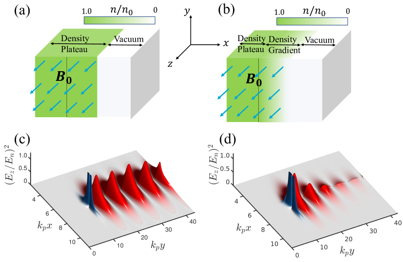
In this letter, we present collisionless damping of SPW’s at the edge of a magnetized plasma. Using analytical techniques and ab-initio first-principles particle-in-cell (PIC) simulations, we demonstrate that for a certain range of parameters, SPW’s damp due to resonant coupling with the bulk plasma modes. To establish necessary and sufficient condition for collisionless damping, we use two different plasma density profiles as illustrated in Fig. 1(a) (setup I) and 1(b) (setup II). In setup I, plasma has a uniform density profile in , directions and a step function density profile in direction, hereinafter called infinitely sharp plasma-vacuum interface (ISPVI). In setup II, plasma has a uniform density in , directions and a linearly falling density profile in direction, hereinafter called smooth plasma-vacuum interface (SPVI). In both setups, the external magnetic field () is stationary and uniform. The SPW’s are excited using a periodic chain (along direction) of non-evolving non-relativistic oscillating point dipole source and kept near the interface. The excited SPW’s propagate along the interface (plane) between bulk-magnetized plasma and vacuum. In Fig. 1(c,d), we have plotted a snapshot of electrostatic energy () associated with component of the electric field at a fixed plane, where blue and red colors correspond to dipole radiation and excited topological SPW’s, respectively.
In setup I (ISPVI), plasma wave modes are not continuous, and there is a gap between frequencies of edge states and bulk modes. Thus, the SPW propagates along the plasma surface in plane without any damping, backscattering, diffraction, and imperfections shown in Fig. 1(c).
In setup II (SPVI), as shown in Fig. 1d, the SPW propagates along the interface, however, undergoes collisionless damping. It turns out that the response of an SPVI contains a continuous spectrum of frequencies, unlike the response of an ISPVI, which only supports a single surface mode and bulk plasma modes. Undamped topological surface mode, at an ISPVI, becomes a weakly damped quasi-modeShvets and Li (1999) as the plasma-vacuum interface (PVI) is smoothed out. For an inhomogeneous plasma, a resonant location exists, where the surface mode frequency is equal to the local upper-hybrid (UH) frequency. As a result of the coupling between the surface and the UH mode, the former damps. Basically, we study how topologically protected edge states manifest themselves on the boundary of magnetized plasma when normal modes of the interface are coupled with bulk modes. We show that topologically protected edge states are immune to backscattering despite their coupling with the bulk modes.
We begin constructing a theoretical model by adopting a cold fluid description of a magnetized plasma in a Cartesian coordinate system. We use the plasma density profile described in setup II (SPVI) and illustrated in Fig. 1(b). We are interested in the high frequency modes thus only electrons are kept mobile and ions merely provide an immobile neutralizing background. We assume that electric () and magnetic fields () are proportional to , where and are the wavenumbers in the and directions. Temporal or spatial damping rate () of SPW’s can be calculated using either complex frequency () or complex wavenumber (), respectively Archambault et al. (2009). After space-time Fourier transformation of Maxwell equations Jackson (2003), , , we obtain a set of linearized differential equations
| (1) | ||||
| (2) |
| (3) |
| (4) |
where are components of cold plasma dielectric tensor Stix (1992). The dissipation is assumed to be infinitesimally small . Here subscript , , show the component of electromagnetic fields in , and direction, , the wave frequency, the speed of light, , the plasma frequency for the maximum density , and are the electric charge and mass of an electron and is the cold plasma skin depth.
The solution for the waves localized near the PVI can be written as a combination of two independent solutions with the coefficients and in plasma and , in vacuum. The dispersion relation for SPW’s is obtained by matching localized solutions for the appropriate boundary conditions at the PVI. The boundary conditions are evaluated by integrating eqs (1-4) over the PVI. For low frequency SPW’s on SPVI, transverse permittivity remains positive everywhere and the waves propagate without damping (Parker et al., 2020b; Fu and Qin, 2021). The boundary conditions turn out to be , where superscript represents components in plasma (vacuum). For high-frequency surface waves (), the upper-hybrid resonance becomes accessible and the transverse permittivity becomes zero () at the position of resonant layer () such that . As a result, the terms having factor become singular (poles) in equations (3) and (4). It is worth mentioning that when electromagnetic wave (SPW) has a singularity near the point where the dielectric function for electrostatic waves vanishes the electromagnetic wave can be converted into an electrostatic wave and anomalous absorption of the electromagnetic wave energy takes place with the generation of large-amplitude electrostatic waves. Grebogi et al. (1977). The anomalous absorption leads to the damping of SPW’s.
We consider that inhomogeneity in plasma density varies linearly, i.e., , where is a length scale over which density decays. The position of the resonant point can be written as , so within the ramp and , where and . To obtain the boundary conditions, we assume that plasma inhomogeneity scale length is very small () and components of the electromagnetic fields are almost constant within the ramp such that R.H.S. of eqns (1)-(4) does not change significantly. Then integration of equations (3) and (4) yields contributions from imaginary part to the poles at the resonance layer as We obtain following boundary conditions imposed on field components , and , where is an algebraic quantity and defined in the supplemental sup . Using the boundary conditions, dispersion relation for SPW’s can be written as
| (5) |
where , , , , and are algebraic coefficients and defined in the supplemental sup ..
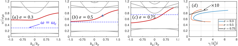
We fix parallel wavenumber to reduce the dispersion relation in two dimensions. It must be noted that in the limit ; where and , SPW’s band gap overlaps with the EM waves in the vacuum, and modes radiate heavily for low values in the vacuum, however, for the wavenumber , bulk-boundary correspondence implies the existence of multiple nontrivial topological modes in the common band gap between trivial vacuum and nontrivial plasma (Parker et al., 2020b). We plotted the dispersion relation for the cyclotron frequencies and the fixed parallel wavenumber in Fig. 2(a-c). The gray dots in Fig. 2(a-c) represent dispersion relation for bulk modes while a transitioning mode (red line) from lower bulk modes to upper bulk modes represents SPW dispersion relation. The SPW modes are chiral and do not scatter due to the lack of other existing modes. The common bulk band gap shrinks with increasing cyclotron frequencies but the range of SPW modes increases. The spatial damping rate () is shown in Fig. 2(d) for different cyclotron frequencies, which turns out to be minimum for long wavelength modes and increases for short wavelength modes. It must be noticed that the damping rate becomes smaller as cyclotron frequency increases but increases with increasing ramp length and remains non-zero and positive only for high frequency modes. Our model breaks down for a very large ramp length but correctly produces the dispersion diagram of SPW’s. In the next section, we will compare the spatial damping rate with that obtained from the PIC simulation of an SPW.
PIC Simulation.- After constructing the theoretical dispersion relation we now confirm it with PIC simulation. We use simulation model illustrated in Fig. 1(b). The plasma density is maximum () and uniform from to and varies linearly (ramp) from maximum to within length from to . The dipole source is kept at , which excites propagating edge modes in plane for positive (negative) external magnetic field ().
We have used 3D first-principles PIC simulation code(VLPL PUKHOV (1999)). The simulation box size is . The spatial and temporal resolutions are , , and , respectively. We have used 4 particles per cell. The simulation box has periodic boundaries in the direction for both particles and electromagnetic fields, absorbing in and directions for electromagnetic fields and reflecting for particles.
The electric () and magnetic () fields are normalized by a numerical factor and to make their amplitude unity, where . The time and position are normalized by and .
For , we choose . Note that, for the frequency range , only Hermitian effects (undamped modes) will prevail thus is prerequisite for having damped edge states. We excite the mode with frequency , wavenumber .
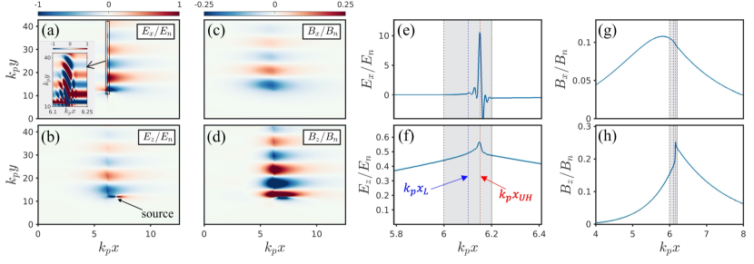
Fig. 3 shows the time snapshot of and components of (a-b) electric and (c-d)magnetic field in the color scale in plane and 3(e-f) shows their 1D direction variation at , respectively. The shaded region shows a linear density ramp where density falls off linearly from left to right. The far left and far right vertical black dot-dash lines correspond to the start and end of the density ramp, the blue and red vertical dashed lines respectively show theoretically predicted positions of Langmuir () and upper-hybrid () resonance layer. For the SPW mode , the Langmuir and upper-hybrid-resonance layer positions are located at and respectively. The SPW’s are excited at and propagate in the plane. SPW’s propagate in the orthogonal plane of the plasma-vacuum interface. The wavenumber () obtained from the simulation is in excellent agreement with theoretical predicted wavenumber .
A strong coupling between upper-hybrid (electrostatic) and SPW’s (electromagnetic) modes leads to the resonance absorption near theoretically predicted position (), consequently SPW’s undergo linear collisionless damping. In Fig. 3(a-d) electromagnetic field components show exponential decay of the intensity in the direction. The normal component of the electric field becomes singular at the resonant layer and has the dependence . In Fig. 3 (a), is shown, which is discontinuous around the resonance layer and evanescent in both vacuum and plasma. Inset shows enhancement of the electric field at the position of resonance layer and can be identified as the upper-hybrid (UH) modes. The UH modes are excited with the same periodicity as SPW’s and due to continuous resonance absorption, their intensity grows higher than the SPW’s amplitude at the end of simulation time. The normal component of the magnetic field is continuous and peaks inside the plasma. The parallel component of the electric () and magnetic () field is discontinuous at the position of UH resonance. It can be clearly seen that electromagnetic fields follow the boundary conditions obtained for the development of the SPW’s dispersion relation. It must be noticed that UH modes are electrostatic because at the resonant layer . The SPW’s are nonrelativistic so their phase mixing and other non-linear effects do not occur in the interested time scale.
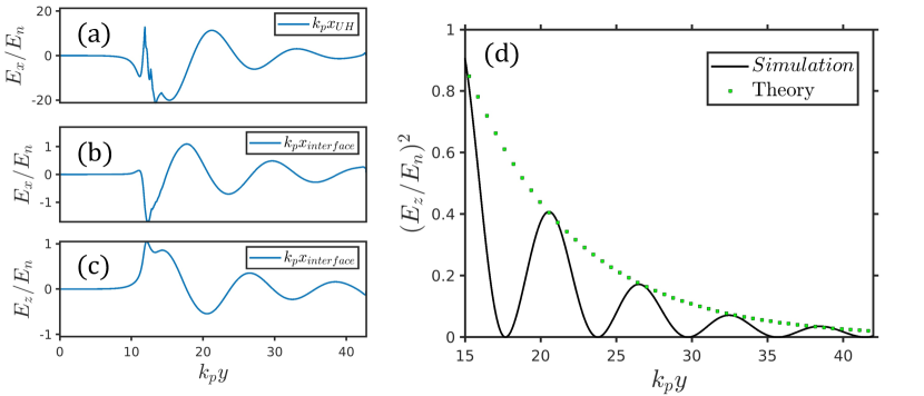
Fig. 4(a) shows y-direction evolution of at the position and (b,c) shows and at the positions and at the edge of plasma-vacuum interface. Interestingly, UH mode follows the same damping rate as the SPW mode at the interface, however, after a long time UH mode saturates due to insufficient resolution of plasma profile in the simulation. In Fig. 4(d), the continuous black line shows the direction evolution of at the interface and is taken from the simulation while the green dotted line shows its numerical fit using theoretical spatial damping coefficient (). The damping rate is in excellent agreement with the theoretically predicted value . Our theoretical model is valid only for small ramp length, however, it correctly predicts that damping rate increases with increasing ramp length, which has been confirmed by carrying out PIC simulation of SPW’s for the ramp length .
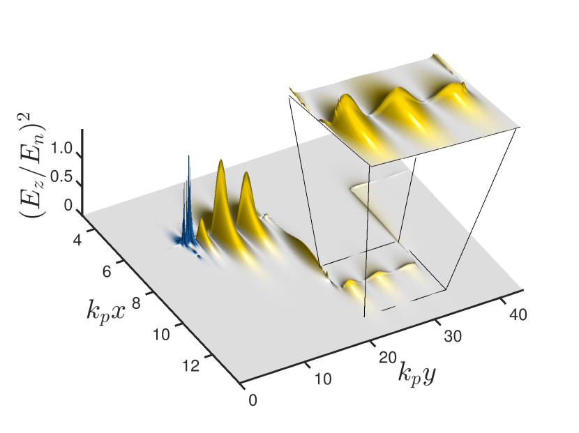
Topological Protection.- When encountered with a discontinuity (Davoyan and Engheta, 2013), the edge states route around any obstacles placed in their path, with no reflections and scattering, because of the nonexistence of backward-propagating edge states. To demonstrate topological protection, we introduce a rectangular discontinuity in the propagation direction of SPW’s at the plasma-vacuum interface which consists of the same species and density profile as the main plasma. The discontinuity contains same scale of density inhomogeneity as main plasma in both and directions; the dimensions of the discontinuity are and kept at . The ramp length is . The SPW’s are excited at . In Fig. 5 we show where blue and yellow colors represent dipole radiation and SPW’s, respectively. When SPW’s encounter discontinuity, they propagate around it seamlessly without any reflection and radiation henceforth demonstrating topological protection. Note that, the collisionless damping observed before and around the discontinuity (see inset of Fig. 5) is a manifestation of the resonance absorption of SPW’s. Remarkably SPWs, even though undergoing collisionless damping, still show topological protection. Their wavenumber and frequency do not change while propagating around the discontinuity.
In summary, we demonstrate collisionless damping of topological surface waves at the edge of magnetized plasma. We have shown that edge states can exist at the plasma-vacuum interface for certain choices of external magnetic field and wavenumber . We have developed a theoretical model and presented a dispersion relation for limiting case () and have shown that the spatial damping rate increases with the increasing ramp length. For the sake of developing a theoretical model, we have chosen the scale length of inhomogeneity very small, nevertheless, we have observed via PIC simulation that collisionless damping of edge states occurs for an arbitrary range of scale length. The collisionlessly damped SPW’s follow topological protection and propagates around different geometrical discontinuities. We believe that topologically protected damped SPW’s if, carefully engineered, can be used in heating arbitrary shaped plasmas.
Acknowledgements.
The work was supported by Air Force of Scientific Research (AFOSR) through Stanford University under MURI Award no. FA9550-21-1-0244. The authors thank the Texas Advanced Computing Center (TACC) at The University of Texas at Austin for providing HPC resources.References
- Ozawa et al. (2019) T. Ozawa, H. M. Price, A. Amo, N. Goldman, M. Hafezi, L. Lu, M. C. Rechtsman, D. Schuster, J. Simon, O. Zilberberg, and I. Carusotto, Rev. Mod. Phys. 91, 015006 (2019).
- Hasan and Kane (2010) M. Z. Hasan and C. L. Kane, Rev. Mod. Phys. 82, 3045 (2010).
- Silveirinha (2019) M. G. Silveirinha, Phys. Rev. B 99, 125155 (2019).
- Klitzing et al. (1980) K. v. Klitzing, G. Dorda, and M. Pepper, Phys. Rev. Lett. 45, 494 (1980).
- Haldane and Raghu (2008) F. D. M. Haldane and S. Raghu, Phys. Rev. Lett. 100, 013904 (2008).
- Raghu and Haldane (2008) S. Raghu and F. D. M. Haldane, Phys. Rev. A 78, 033834 (2008).
- Goldman et al. (2016) N. Goldman, J. C. Budich, and P. Zoller, Nature Physics 12, 639 (2016).
- Silveirinha (2015) M. G. Silveirinha, Phys. Rev. B 92, 125153 (2015).
- Tauber et al. (2019) C. Tauber, P. Delplace, and A. Venaille, Journal of Fluid Mechanics 868, R2 (2019).
- Gao et al. (2016) W. Gao, B. Yang, M. Lawrence, F. Fang, B. Béri, and S. Zhang, Nature Communications 7, 12435 (2016).
- Yang et al. (2016) B. Yang, M. Lawrence, W. Gao, Q. Guo, and S. Zhang, Scientific Reports 6, 21461 (2016).
- Parker et al. (2020a) J. B. Parker, J. W. Burby, J. B. Marston, and S. M. Tobias, Phys. Rev. Research 2, 033425 (2020a).
- Parker et al. (2020b) J. B. Parker, J. B. Marston, S. M. Tobias, and Z. Zhu, Phys. Rev. Lett. 124, 195001 (2020b).
- Parker (2021) J. B. Parker, Journal of Plasma Physics 87, 835870202 (2021).
- Fu and Qin (2021) Y. Fu and H. Qin, Nature Communications 12, 3924 (2021).
- Pakniyat et al. (2020) S. Pakniyat, A. M. Holmes, G. W. Hanson, S. A. H. Gangaraj, M. Antezza, M. G. Silveirinha, S. Jam, and F. Monticone, IEEE Transactions on Antennas and Propagation 68, 3718 (2020).
- Shvets and Li (1999) G. Shvets and X. Li, Physics of Plasmas 6, 591 (1999), https://doi.org/10.1063/1.873204 .
- Archambault et al. (2009) A. Archambault, T. V. Teperik, F. Marquier, and J. J. Greffet, Phys. Rev. B 79, 195414 (2009).
- Jackson (2003) J. D. Jackson, “Electrodynamics, classical,” in digital Encyclopedia of Applied Physics (American Cancer Society, 2003).
- Stix (1992) T. Stix, Waves in Plasmas (American Inst. of Physics, 1992).
- Grebogi et al. (1977) C. Grebogi, C. S. Liu, and V. K. Tripathi, Phys. Rev. Lett. 39, 338 (1977).
- (22) .
- PUKHOV (1999) A. PUKHOV, Journal of Plasma Physics 61, 425–433 (1999).
- Davoyan and Engheta (2013) A. R. Davoyan and N. Engheta, Phys. Rev. Lett. 111, 257401 (2013).