A Context-Aware Readout System
for Sparse Touch Sensing Array
Using Ultra-low-power Always-on Event Detection
Abstract
Increasing demand for larger touch screen panels (TSPs) places more energy burden to mobile systems with conventional sensing methods. To mitigate this problem, taking advantage of the touch event sparsity, this paper proposes a novel TSP readout system that can obtain huge energy saving by turning off the readout circuits when none of the sensors are activated. To this end, a novel ultra-low-power always-on event and region of interest detection based on lightweight compressed sensing is proposed. Exploiting the proposed event detector, the context-aware TSP readout system, which can improve the energy efficiency by up to 42, is presented.
Index Terms:
Capacitive touch sensor, sensor array, compressed sensing, sparse event detection, always-on event detection, context-aware systemI Introduction
Capacitive sensors have been used for decades, recognized for its stability of operation in temperature variations and high sensing accuracy in various fields including touch screen panel (TSP) technology. Many products such as mobile phones, tablets, and TVs take advantage of TSPs, and the demand for larger and faster TSPs keeps increasing. However, larger TSPs increase the number of sensors in an array and requires faster readout circuit, both of which exacerbate the energy dissipation. Since energy efficiency is a huge concern for mobile systems, this calls for a new technique to achieve the excellent energy efficiency with large TSPs. Noticing that turning on the readout circuits all the time is energy consuming and that only a small fraction of sensors is activated for most TSP applications, this paper proposes a novel TSP readout system that can obtain huge energy saving by turning off the readout circuits when none of the sensors are activated. To this end, this paper proposes a novel ultra-low-power always-on event, or region-of-interest, detection using lightweight compressed sensing. Moreover, exploiting the proposed event detector implemented in RTL and synthesized in a 28 nm process, this paper presents a context-aware TSP readout system, which can improve the energy efficiency by up to 42 over conventional systems.
II Background
II-A Touch Sensor Array & Readout Circuits
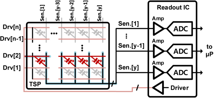
Fig. 1 shows the overall block diagram of a TSP and interface readout circuits. The TSP is composed of multiple driving and sensing channels. The touch information is embedded in the mutual capacitance , which is the parasitic capacitance between the driving channel and the sensing channel. under the region, where fingers are touched, is reduced, and the driver applies an excitation signal to each driving channel, Drv[i], to measure . The excitation signals modulated by are transferred through the sensing channels to the readout circuit, where the small input signal is amplified and digitized. The main components in the readout integrated circuits (ICs) are the charge amplifier, the analog-to-digital converter (ADC), and the driver, and the amount of power consumed by these components depends on the performance metric such as frame rate and signal-to-noise ratio (SNR). Although each block can be designed to minimize the power individually while satisfying the required performance, there is fundamental trade-off between the frame rate, SNR, and power consumption [1]. Better performance, e.g. higher frame rate and SNR, inevitably incurs higher power consumption.
Although the circuit-level design techniques have improved the performance significantly, these techniques alone are not sufficient to support the increasing demand for TSPs with larger sizes because the number of sensors and the power of the readout circuits increase accordingly. This is especially undesirable for systems like mobile devices with severe energy constraints. This problem can be mitigated with the help of various system-level approaches, among which how to access and read multiple sensors and how to extract the wanted information will be introduced in the next section.
II-B Existing Sensing Techniques
Since each column-wise signal path reads ’s modulated by the driving signals, the measured values by ADCs can be expressed as: where is mutual capacitances in the column (, in Fig. 1). is the sensing (measurement) matrix determining how to modulate the driving channel, and represents circuit random noise.
II-B1 Time Division Multiplexed Sensing (TDM)
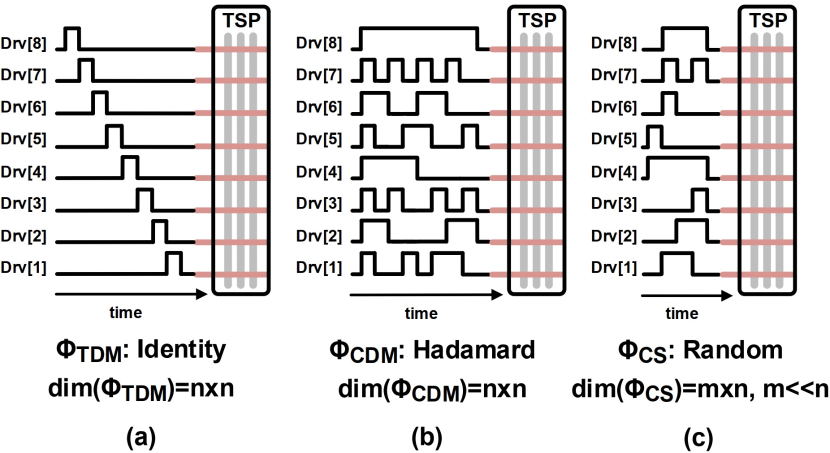
The simplest way to read out data from a sensor array is to use the TDM scheme [2] (see Fig. 2 (a)). is the identity matrix, so it requires no extra signal recovery phase, i.e. for each column. Despite its simplicity, the energy efficiency of TDM becomes severely degraded as the number of sensors increases. For instance, if the number of sensors becomes twice while the frame rate is fixed, the allocated time for reading each sensor becomes half. Then, the power consumption of the readout circuits becomes more than twice for 2 higher bandwidth while maintaining the same SNR. Thus, when the TSP size or when the required frame rate is large (around hundreds Hz), the overall energy consumption of TDM becomes unacceptable in mobile systems.
II-B2 Code Division Multiplexed Sensing (CDM)
Applying CDM for reading out the touch sensor array data has been introduced in [3, 4]. is an orthogonal matrix, and since all the orthogonal matrices are invertible and the inverse is its transpose, the sensor data can be recovered by . In theory, any orthogonal matrix can be used, but if the elements of are composed of +1/0/-1, then it becomes simple to implement in hardware. For instance, Hadamard matrix is used in [3]. CDM helps reduce noise in the signal recovery phase and achieve higher SNR if the noise is independent and identically distributed (i.i.d.).
However, like TDM, CDM also should measure as many samples as the number of sensors, which increases the power of the amplifiers and ADCs with large TSPs. Moreover, the dynamic power of the driver in Fig. 1 also increases dramatically because the CDM driver should keep switching during the whole sensing period (see Fig. 2 (b)) and the parasitic capacitance of the driving channels increases as the TSP size gets larger. Therefore, CDM also suffers from degraded energy efficiency with large TSPs.
II-B3 Compressed Sensing (CS)
CS has been introduced to read out sparse data from sensor arrays [5]. The distinct feature of CS is that it does not require as many samples as TDM or CDM does, thereby making it possible to save huge amount of energy consumed by the readout circuits. is an rectangular matrix with , yielding an under-determined recovery equation. Still, if is sparse, it is possible to recover using properly chosen . In practice, however, there are two main difficulties that prevent CS from being used for mobile systems.
First, to take advantage of CS, we need to construct a measurement matrix that satisfies the Restricted Isometry Property (RIP) [6]. However, constructing such matrices is hard, so most of the measurement matrix is built using random elements. Dense random matrices, where the elements are generated by an i.i.d. Gaussian or Bernoulli process, are widely used in CS because they satisfy RIP with high probability [7]. Due to simplicity, Bernoulli matrices composed of binary elements, +1/-1, are preferred, but still they require an on-chip random seed or a large memory to store them. In order to apply CS for TSPs with small memory overhead, Bernoulli matrix and its circulant version were used in [8, 9]. Pursuing lower complexity for implementation, [10] exploited deterministic matrices for CS.
The bigger issue of using CS in mobile systems stems from the complex signal recovery algorithms. Using minimization, which provides theoretical guarantees for signal recovery [11], requires huge computation and time. Due to computational simplicity, greedy algorithms are attractive, and the variants were proposed for TSPs in [8, 9]. However, they still suffer from either high power or low detection probability. Even if we can save huge energy of the readout circuits thanks to CS, the overall system does not gain any benefits due to the computational energy for signal recovery. This has limited the usage of CS to the applications, where signal recovery can be done offline. Thus, conventional CS is not adequate for large TSPs, where not only signal sensing but its recovery should be done in an energy-efficient manner.
III Proposed TSP Readout System
III-A Overall System Description
High-resolution ADCs are typically the most energy-consuming block in conventional TSP readout systems, and since the touch events are sparse in time, great energy saving can be gained if the ADCs are turned off most of the time, and operate only when needed. To build such systems, we propose an ultra-low-power sparse event detection scheme with negligible hardware overhead. With the proposed system, energy saving can be achieved as long as the touch events happen sparsely and the high-resolution ADC is the dominant energy-consuming block in the system.
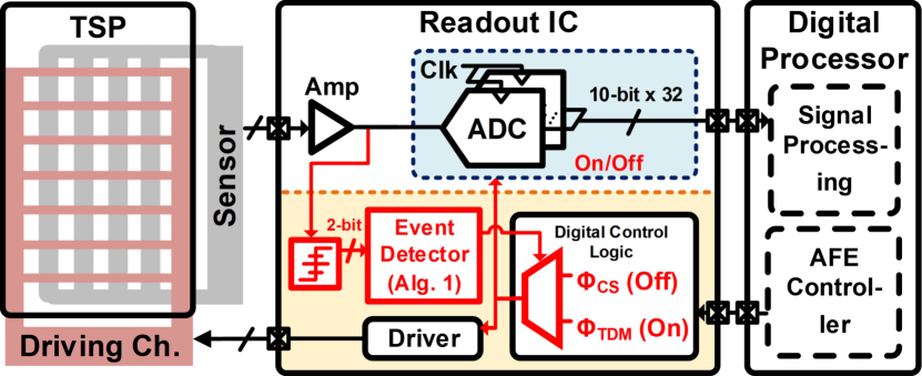
Fig. 3 shows the overall block diagram of the proposed TSP readout system with the following distinct features: 1) ultra-low-power always-on region-of-interest (ROI), or event detection based on CS, and 2) context-aware readout operation by sensing only the regions where the events are detected.
For the event detection, multiple sensors are read simultaneously using the proposed measurement matrix. To discard the need for random number generators and reduce the required memory, the system exploits a deterministic measurement matrix. Furthermore, all the elements in the matrix are composed of either +1, 0, or -1, for hardware simplicity. Taking advantage of the sparsity nature of the touch event, the proposed matrix enables detecting the event and ROI with a simple algorithm, which can be implemented with ultra-low power.
With the help of the ultra-low-power event detection, the proposed sensing system can achieve energy-proportional operation, or context-aware operation [12, 13], which allows the sensing system to figure out the context of sensor data and selectively transmit the data, e.g. activated sensor data only, to the processor. In contrast to conventional systems, the overall power consumption of the proposed one is no longer directly proportional to the total number of sensors but rather proportional to the occurrence of events of interest. For such context-aware systems, since communication between the readout IC and the processor is required only when events occur, communication link I/Os need to support rapid turning on/off operation for overall system energy proportionality [14, 15, 16].
The proposed context-aware readout operation is performed in two steps: 1) event or ROI detection using CS and 2) ROI readout using TDM (see the yellow area of Fig. 3). The system activates only the ultra-low-power event detector to detect the region of activation (described in Section III-B) and then only when detected the sensors in that region are read sequentially using TDM by the high-resolution ADCs (the blue area of Fig. 3). This makes the system power consumption proportional to the number of activated events, not to the number of sensors in a TSP. Since in practice the touch events are sparse not only in location but also in time, the proposed system can save huge amount of power, consuming nearly zero power during when no event happens. Moreover, since only the activated sensors are read sequentially using TDM, the complex signal recovery algorithm by which conventional CS suffers from huge energy consumption can be avoided. Note that the ultra-low-power event detector plays a key role in the proposed system, which will be described next.
III-B Proposed Event Detection
The proposed deterministic measurement matrix for sparse touch event detection is constructed as follows. Let denote a column vector whose -th element is 1 and all the other elements are zero, and let denote a column vector whose elements in -th to -th positions are -1 and all the others are zero. In other words, . Then the columns of are composed of ’s and ’s as described below. (For simplicity, suppose that is an integer multiple of in which case .)
For example, when is 2, can be expressed as
The sensing matrix is designed using ternary elements such that any or less than columns of the matrix are linearly independent. This guarantees that any -sparse signals can be detected by monitoring whether the measurements are zero (noiseless) or close to zero (in the presence of noise). Since the signal of interest is always positive in TSP, the index of the activated sensors can be identified by checking the sign of the measurements and their magnitude. Note that since , less number of measurements is required to recover -sparse signals from sensors. In other words, with , the sampling ratio is ( samples from sensors). Compared to conventional CS, the sampling ratio with has the following downsides: 1) it does not approach zero asymptotically as increases, and 2) it approaches 1 as increases, implying that the required number of samples is almost the same as the number of sensors like TDM or CDM. However, the structured nature of provides a very simple way to detect the active sensors. We first search negative measurements and find the active sensors in the index . If none of the sensors in the index are active, any non-zero measurements should appear in consecutive indexes. If negative values do not appear consecutively, we can easily find out which sensors in the index are active. Note that only simple operations such as comparison or addition are required for detection, allowing low energy consumption. One may think that detecting ROI would be possible by driving multiple sensors simultaneously and comparing the output with a certain threshold. However, the sensor output is composed of a large DC and a small varying component that needs to be detected, and simply driving multiple sensors with one adds up the DC components of the sensor outputs, which greatly reduces the dynamic range of the analog circuits such as amplifiers and ADCs. To prevent this, the sensing matrix is designed such that the elements in each row are summed to zero and the DC components of the sensor outputs can be canceled out each other.
Using the structure of , a new measurement matrix with the improved sampling ratio is constructed by repeating each column of times, where is a design parameter chosen based on the sparsity and the total number of sensors . and are decided by the system specifications, while and should be chosen by a designer to satisfy , where . If , some columns of are repeated times, rather than times to make the size . This construction allows us to think of (or ) chunks of sensors as a single sensor, and we can apply the same detection algorithm to find out which sensor chunks are activated. In other words, the -sparse signal can be detected from sensors using only samples, i.e. sampling ratio being . The event detection process with works the same as the one with , except that sensors in a chunk are treated as one sensor. When a sensor is detected active with , all sensors in the chunk are considered candidates for being active.
Taking noise into account, the measured values are compared with properly chosen thresholds (Vth) and quantized into 4 levels: , and . The quantized measurements are processed using Alg. 1 for ROI detection. We first search for the location of the large negative samples in the measurement (corresponding to first if-statement in Alg. 1). This provides the information about the index of the activated sensors. Then, the consecutive samples associated with the sensors considered activated are checked whether some of the samples are close to zero. If so, this provides additional information about the index of other activated sensors (corresponding to second if-statement in Alg. 1). If none of the measured samples are negative with large magnitude, none of the last sensors are activated. Then, we search for the positive samples with large magnitude and identify the index of the activated sensors (corresponding to else-statement in Alg. 1). Only the sensors in the detected chunks are read sequentially using TDM.
IV Experiments
Ideally, the proposed system should only read the sensors in the activated chunks. However, due to noise, inactive chunks could be falsely detected as active. Note that false alarm incurs energy overhead since inactive sensors are read unnecessarily and it should be minimized.
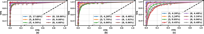
We evaluated Alg. 1 with different values of sparsity (5, 8) and total number of sensors (1000, 5000, 10000)111 A high-resolution TSP such as the one reported in [17] with a 1 mm-pitch allows more natural human interfaces and highly accurate expressions, which are required for a variety of applications. Scaling up the 248 sensors with a 6.25 mm pitch presented in [18] to a 1 mm pitch leads to 1550 sensors in each column. This would result in using up to - sensors in the future as the TSP size increases proportionately. .
For each set of and , different number of samples and number of sensors in a chunk were chosen. Then, for each parameter set, Vth in Alg. 1 was swept to obtain various receiver operating characteristic (ROC) curves, plotted in Fig. 4. Fig. 4 (a) was obtained with 25 dB TSP SNR and 40 dB readout circuits SNR while (b) and (c) were with 30 dB SNR for TSP [19]. When =1000 with 30 dB TSP SNR, all cases of and sampling ratio showed the perfect ROC curves, so lower TSP SNR of 25 dB was tested when =1000. The star markers in Fig. 4 show the ROC of a slightly modified detection algorithm, where additional post-processing is performed to reduce the false positive rate (FPR), e.g. considering the chunk is falsely activated if the chunk contains both above-(+Vth) and below-(-Vth) values. From Fig. 4, we can see that the sampling ratio around 4.2 % in 30 dB and 40 dB SNR shows the perfect detection, while true positive rate (TPR) and FPR get worse as the sampling ratio reduces.
The proposed sparse event detector that runs Alg. 1 was synthesized in a 28 nm CMOS process. It is implemented with compact combinational logic blocks composed of counters, comparators, and logic gates taking 2-bit (coarsely quantized) inputs and generating as output a binary vector. It indicates whether the event is detected or not at the corresponding cell.
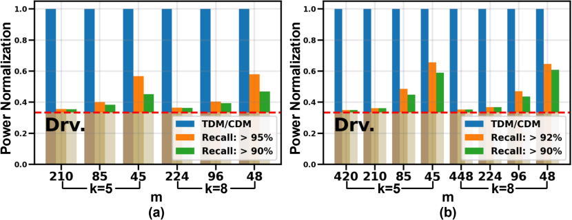
The logic area depends on the maximum frame-rate and the sparsity parameter , which are decided by the system or application requirement. The operating clock frequency is set to meet the maximum TSP frame rate 200 Hz. The detector is always on with minimal power overhead, and all the readout circuits can be turned off unless any event is detected. Based on [4], power models for an amplifier, ADC, and driver were built: 0.3 mW per channel for driver, 0.2 mW per channel for amplifier, and 0.4 mW per channel for ADC at 120 Hz frame rate. We adopted it for the existing circuits, and the area and power overhead of the proposed digital block were obtained from the RTL synthesis result. Fig. 5 shows 2.14 - 42.47 energy saving of the proposed readout system over conventional sensing methods with recall 90 %.
| Prop. Detector | [4] | [20] | [21] | |
|---|---|---|---|---|
| Process | 28 nm | 180 nm | 350 nm | 130 nm |
| Scaled area | 66.61 | 0.87 | 0.04 | 3.35 |
| Power | w/o detector | 0.6 | 0.25 | 1.49 |
| (mW/channel) | w/ detector | 0.014-0.28 | 0.007-0.12 | 0.047-0.72 |
| Power saving | - | 2.1-42.5 | 2.1-33.7 | 2.1-31.7 |
Similarly, we also quantified how much power saving can be obtained from other works using the proposed detector, and the results demonstrate a significant reduction in power consumption. It saves power of 2.06 - 33.66 in [20] and 2.06 - 31.71 in [21] using the proposed context-aware readout operation. The proposed detector occupies 33.23 m2, 52.42 m2, and 66.61 m2 for =5, 8, and 10, respectively. In comparison, the active areas of the readout circuits (including analog front-end and high-resolution ADCs) in [4], [20], and [21] are 36 mm2, 5.52 mm2, and 72.25 mm2, respectively. Even with perfect scaling to a 28 nm process, they are scaled down to 0.87 mm2, 0.04 mm2, and 3.35 mm2. On the other hand, the proposed detector occupies only 66.61 m2 when =10, which indicates that the area overhead of the proposed detector is negligible. Table I summarizes the area overhead and power-saving gain of the proposed system.
Since the same number of measurements is read for TDM and CDM, the amplifier bandwidth and ADC sampling rate should be the same when the frame rate and the number of sensors are both the same. This results in the same power usage for TDM and CDM. On the other hand, the proposed context-aware readout system power is divided into two parts, the sparse event detector and the sequential readout, using the power models and the simulated TPR/FPR, the total power saving is simulated for each parameter set. There is a trade-off between the sampling ratio and power consumption that if is big, which means we compressed more sensors into small value of , consumes more power than that using bigger .
V Conclusion
This paper presents a context-aware readout system for large TSPs equipped with an ultra-low-power always-on event or ROI detector. Taking advantage of touch event sparsity, a novel sensing matrix and a simple ROI detection algorithm that can identify the activated sensor regions with small number of measurements are proposed. Instead of turning on the readout circuits all the time, it allows the overall system to save huge amount of energy by turning off the readout circuits when none of the sensors are activated, improving the energy efficiency by up to 42 over conventional always-on readout systems.
Acknowledgment
The EDA Tool was supported by the IC Design Education Center (IDEC), Korea.
References
- [1] B. Razavi, Design of Analog CMOS Integrated Circuits. Tata McGraw-Hill Education, 2002.
- [2] J.-E. Park, D.-H. Lim, and D.-K. Jeong, “A reconfigurable 40-to-67 dB SNR, 50-to-6400 Hz frame-rate, column-parallel readout IC for capacitive touch-screen panels,” IEEE Journal of Solid-State Circuits, vol. 49, no. 10, pp. 2305–2318, 2014.
- [3] C. Park, S. Park, K.-D. Kim, S. Park, J. Park, B. Kang, Y. Huh, and G.-H. Cho, “A pen-pressure-sensitive capacitive touch system using electrically coupled resonance pen,” IEEE Journal of Solid-State Circuits, vol. 51, no. 1, pp. 168–176, 2016.
- [4] J.-E. Park, Y.-H. Hwang, and D.-K. Jeong, “A Noise-Immunity-Enhanced Analog Front-End for 36 × 64 Touch-Screen Controllers With 20-VPP Noise Tolerance at 100 kHz,” IEEE Journal of Solid-State Circuits, vol. 54, no. 5, pp. 1497–1510, 2019.
- [5] D. L. Donoho, “Compressed sensing,” IEEE Transactions on Information Theory, vol. 52, no. 4, pp. 1289–1306, Apr. 2006.
- [6] E. J. Candes and T. Tao, “Decoding by linear programming,” IEEE Transactions on Information Theory, vol. 51, no. 12, pp. 4203–4215, 2005.
- [7] R. Baraniuk, M. Davenport, R. DeVore, and M. Wakin, “A simple proof of the restricted isometry property for random matrices,” Constructive Approximation, vol. 28, no. 3, pp. 253–263, 2008.
- [8] C. Luo, M. A. Borkar, A. J. Redfern, and J. H. McClellan, “Compressive sensing for sparse touch detection on capacitive touch screens,” IEEE Journal on Emerging and Selected Topics in Circuits and Systems, vol. 2, no. 3, pp. 639–648, 2012.
- [9] C. Luo, “A low power self-capacitive touch sensing analog front end with sparse multi-touch detection,” in IEEE International Conference on Acoustics, Speech and Signal Processing (ICASSP), 2014, pp. 3007–3011.
- [10] A. Amini and F. Marvasti, “Deterministic construction of binary, bipolar, and ternary compressed sensing matrices,” IEEE Transactions on Information Theory, vol. 57, no. 4, pp. 2360–2370, 2011.
- [11] D. Needell, J. Tropp, and R. Vershynin, “Greedy signal recovery review,” in Signals, Systems and Computers, 2008 42nd Asilomar Conference on. IEEE, 2008, pp. 1048–1050.
- [12] L. A. Barroso and U. Hölzle, “The case for energy-proportional computing,” Computer, vol. 40, no. 12, 2007.
- [13] S. Venkataramani, V. Bahl, X. S. Hua, J. Liu, J. Li, M. Phillipose, B. Priyantha, and M. Shoaib, “SAPPHIRE: An always-on context-aware computer vision system for portable devices,” in Design, Automation Test in Europe Conference Exhibition (DATE), 2015, pp. 1491–1496.
- [14] W.-S. Choi, T. Anand, G. Shu, A. Elshazly, and P. K. Hanumolu, “A burst-mode digital receiver with programmable input jitter filtering for energy proportional links,” IEEE Journal of Solid-State Circuits, vol. 50, no. 3, pp. 737–748, 2015.
- [15] G. Shu, W.-S. Choi, S. Saxena, S.-J. Kim, M. Talegaonkar, R. Nandwana, A. Elkholy, D. Wei, T. Nandi, and P. K. Hanumolu, “A 16Mb/s-to-8Gb/s 14.1-to-5.9 pJ/b source synchronous transceiver using DVFS and rapid on/off in 65nm CMOS,” in IEEE International Solid-State Circuits Conference, 2016, pp. 398–399.
- [16] D. Kim, M. G. Ahmed, W.-S. Choi, A. Elkholy, and P. K. Hanumolu, “A 12-Gb/s 10-ns turn-on time rapid on/off baud-rate DFE receiver in 65-nm CMOS,” IEEE Journal of Solid-State Circuits, vol. 55, no. 8, pp. 2196–2205, 2020.
- [17] N. Miura, S. Dosho, S. Takaya, D. Fujimoto, T. Kiriyama, H. Tezuka, T. Miki, H. Yanagawa, and M. Nagata, “A 1mm-pitch 8080-channel 322Hz-frame-rate touch sensor with two-step dual-mode capacitance scan,” in 2014 IEEE International Solid-State Circuits Conference Digest of Technical Papers (ISSCC). IEEE, 2014, pp. 216–217.
- [18] M. Miyamoto, M. Hamaguchi, and A. Nagao, “A 14381 mutual-capacitance touch-sensing analog front-end with parallel drive and differential sensing architecture,” IEEE Journal of Solid-State Circuits, vol. 50, no. 1, pp. 335–343, 2014.
- [19] C. S. Corp., “SNR measurement realities for capacitive touchscreens,” Tech. Rep., 12 2011.
- [20] S.-H. Park, H.-S. Kim, J.-S. Bang, G.-H. Cho, and G.-H. Cho, “A 0.26-nJ/node, 400-kHz Tx driving, filtered fully differential readout IC with parasitic RC time delay reduction technique for 65-in capacitive-type touch screen panel,” IEEE Journal of Solid-State Circuits, vol. 52, no. 2, pp. 528–542, 2016.
- [21] J.-S. An, J.-H. Ra, E. Kang, M. A. Pertijs, and S.-H. Han, “A readout IC for capacitive touch screen panels with 33.9 dB charge-overflow reduction using amplitude-modulated multi-frequency excitation,” IEEE Journal of Solid-State Circuits, vol. 56, no. 11, pp. 3486–3498, 2021.