Modeling of porous lithium metal electrodes: turning the Li-dendrite problem around
Abstract
The properties of rechargeable lithium-ion batteries are determined by the electrochemical and kinetic properties of their constituent materials as well as by their underlying microstructure. Microstructural design can be leveraged to achieve a leap in performance and durability. Here we investigate a porous electrode structure, as a strategy to increase the surface area, and provide structural stability for Li-metal anodes. The porous architecture consists of a mixed electron/ion conductor that function as a scaffold for lithium metal deposition. A new finite element model was developed to simulate the large topological changes associated with Li plating/stripping. This model is used to predict the current density distribution as a function of material and structural properties. A dimensionless quantity that combines Li-ion conductivity, surface impedance and average pore size is shown to be a good indicator to predict the peak current density. Preventing current localization at the separator reduces the risk of cell shorting. The analyses show that the peak current scales as , where is the ratio between surface and bulk conductivity and is the average pore size. Stability analyses suggest that the growth is morphologically stable, and that confining Li-plating into pores can enable high-energy density solid-state batteries. In addition to optimizing porous electrodes design, this finite element method can be extended to studying other Li-battery structures.
Keywords solid state battery lithium metal anode porous architecture mesoscale modeling mixed electron/ion conductor
1 Introduction
The need for fast charging, high energy density, long battery life is currently driving the search for a robust solid-state electrolyte which can enable Li metal electrodes. The attempts in using lithium as a negative electrode in Li-ion batteries have revived in recent years, as the energy density of graphite-based cells is reaching its limits, and the demand for high-energy applications is growing. High-rate, high-capacity cycling of Li metal anodes has been hindered by cell-shorting due to non-uniform Li deposition (forming a dendritic structure), causing the solid electrolyte (SE) layer to fracture [1, 2, 3, 4, 5, 6]. To address this problem, we investigate how a porous electrode structure can self-regulate the local current density and prevent cell shorting. The porous topology provides a scaffold for Li-deposition and stripping, supporting both mechanical integrity and Li-accessibility. The goal of this study is to understand what characteristics (geometry and material properties) are required to achieve stable cycling at current densities relevant to vehicle electrification.
To date, several strategies have been developed to mitigate the dendritic growth of metallic Li. In particular, Li metal storage in three-dimensional (3D) framework electrodes is considered an effective dendrite growth mitigation strategy since these electrodes with large surface areas and high porosity result in reduced local Li plating current densities and further can confine metallic Li within their porous architectures resulting in increased tolerance to volume expansion and associated particle fracture effects [1, 7, 8, 9, 10, 11, 12, 13, 14, 15, 16, 17, 18, 19, 20, 21]. Promising porous electrode strategies include 3D CuZn current collectors [7], Cu current collector and Li composite anodes [8], porous carbon electrodes embedded with high surface area N-doped carbon crystals [9], and with lithiophilic ZnO quantum dots [10]. Effective porous electrode strategies for all-solid-state systems include 3D electron-ion conducting frameworks such as porous garnet electrolytes with carbon nanotube coatings [11], and 3D printing enabled porous garnet microstructures [11, 18]. Most of these strategies, however, exhibit uneven Li plating-stripping because the ionic resistance of the electrolyte filled pores leads to preferential plating-stripping closer to the separator interface [13]. To address this issue, recent research has focused on (i) microstructural engineering and (ii) lithiophillic surface treatment, in order to facilitate more uniform plating-stripping across the entire surface area of the porous electrode [14, 15, 16, 17, 19].
These examples of mesoscale architecture motivate the development of a modeling framework to study the relationship between structure, performance and durability in porous electrodes. Modeling of energy storage materials has, so far, focused on composite electrodes [22, 23, 24, 25, 26, 27, 28, 29, 30]. Here we present a computational method developed to track material growth driven by electro-deposition within a complex geometry. Employing a phase field method to track the Li interface is a possible approach [31, 32, 33, 34, 35, 36, 37, 38, 39, 40]. However, we expect Li-metal regions to not simply merge, but to come in contact, deform and exert stress on the electrode walls. For this reason, we choose to implement a finite element method with a sharp interface representation, and we anticipate adding stress and fracture in future work. We also anticipate that as pores begin to fill, there will be additional terms in the Li diffusion potential. Additionally, the volume change as lithium comes out of solution and plates within the pores creates difficulties in the phase field method.
2 Methods
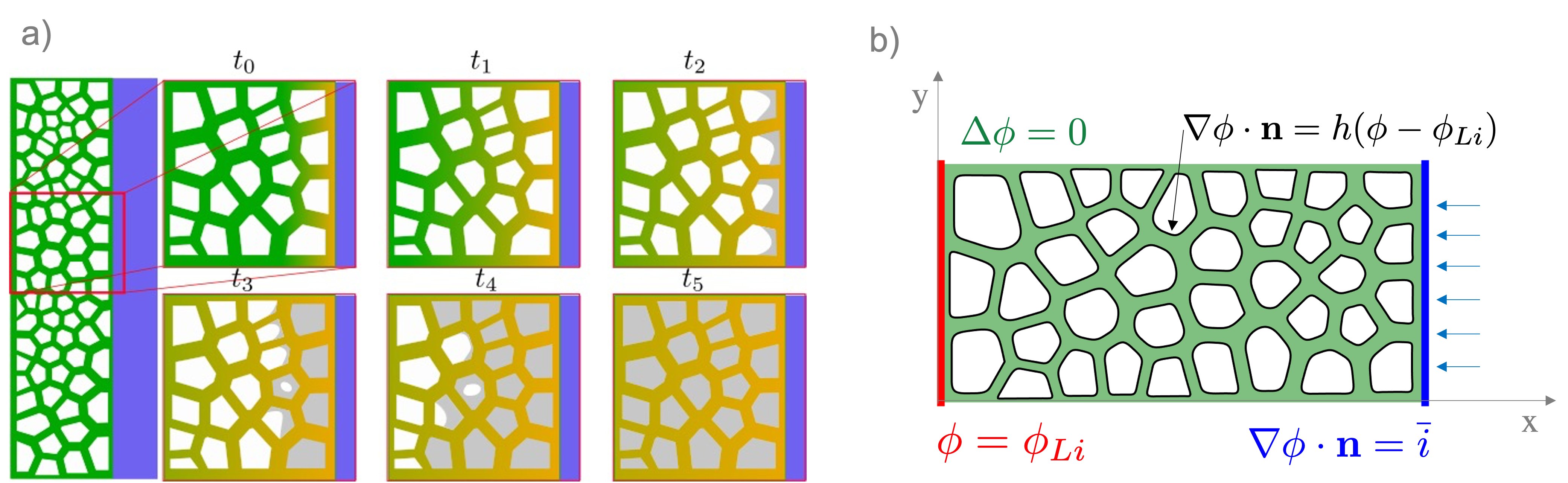
A finite element model was implemented to simulate electro-deposition in a porous electrode structure. In the simulation, the deposition front moves as the cells is the microstructure are filled with lithium (Fig. 1). We assume that the Li plates at the Li/Vapor interface and not the Li/electrolyte interface. The cathode overpotential is the driving force for lithium deposition and it is calculated by solving the electrochemical problem described below. We consider the domain sketched on the left of Fig. 1 as representing a porous solid mixed electron/ion conducting material. Steady-state conduction of Li-ion across the electrode is modeled by the Laplace equation as in Eq. 1a, with the potential of lithium treated as independent variable. A fixed current density is imposed at the separator interface (blue right edge in the figure in Fig. 1). In Eq. 1c, the constant is the ratio between the current density and the electrolyte bulk conductivity . The kinetics at the inner Li/Vapor interface is described by a linear approximation of the Butler-Volmer equation, with the convective coefficient representing the ratio between surface and bulk conductivity. This is the Robin boundary condition in Eq. 1b and applies to the charge-transfer interface. At the negative electrode, the potential is held constant at by the Dirichlet boundary condition Eq. 1d. A zero-flux boundary condition is assumed for the top and bottom edge of the domain.
| (1a) | |||
| (1b) | |||
| (1c) | |||
| (1d) | |||
A two-dimensional model representation is chosen because it provides phenomenology that will translate to 3D. For a square lattice, in the limit of an infinitely thin wall, the surface area scales linearly with the number of cells in each dimension as . The current density distribution changes with the distance from the separator (x axis in Fig. 1), and it is on-average uniform in the other two directions.
For this study we consider microstructures derived from a centroidal Voronoi tessellation, as illustrated in Fig. 1. The pore structure will generally depend on the fabrication method. Here we choose an isotropic structure with closed cells, to demonstrate the model capabilities and derive initial scaling laws.
Electro-deposition is modeled as surface accretion, by assuming that material growth is normal to the Li/Vapor interface. The numerical implementation of the model was coded in the Wolfram Language and simulated using Mathematica 111 https://www.wolfram.com/mathematica. Notable functions used from Version 13.0.0 of Mathematica: NDSolve, BSplineFunction, BoundayMesh, ToElementMesh, BoundaryMeshRegion. Some of the key features of the algorithm are listed below.
2.1 Algorithm
-
1.
The first step involves solving Eq. 1a to compute the current density along the charge-transfer interface . The current density determine the amount of material plated at the interface. The normal velocity field is computed as , with being the Faraday constant and the partial molar volume of Li. The left image below shows electric potential isolines; the right image illustrate the velocity field at the Li/Vapor interface.
![[Uncaptioned image]](/html/2203.05501/assets/x1.png)
![[Uncaptioned image]](/html/2203.05501/assets/x2.png)
-
2.
The product between the normal velocity and the time increment determines the new location of the boundary nodes (illustrated in pink on the left image below). Some regions show high density of points, corresponding to finite elements with high aspect ratio. Re-sampling of the boundary nodes with uniform spacing is performed at each time step to prevent element inversion, and maintain solution accuracy. The re-meshing algorithms is robust with respect convex/concave geometries and non-uniform current distribution.
![[Uncaptioned image]](/html/2203.05501/assets/x3.png)
![[Uncaptioned image]](/html/2203.05501/assets/x4.png)
![[Uncaptioned image]](/html/2203.05501/assets/x5.png)
-
3.
Acute angles or large time steps may cause self-intersection of the boundary. An algorithm was devised the check for self-intersection and remove the nodes within the intersecting segment as shown in the two images below
![[Uncaptioned image]](/html/2203.05501/assets/x6.png)
![[Uncaptioned image]](/html/2203.05501/assets/x7.png)
3 Results
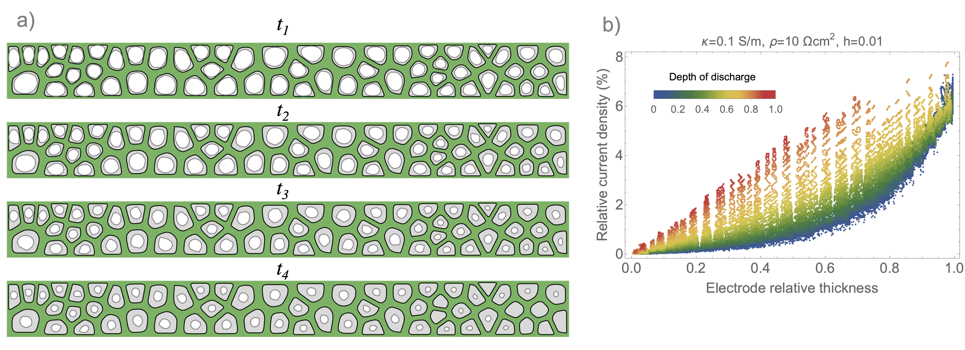
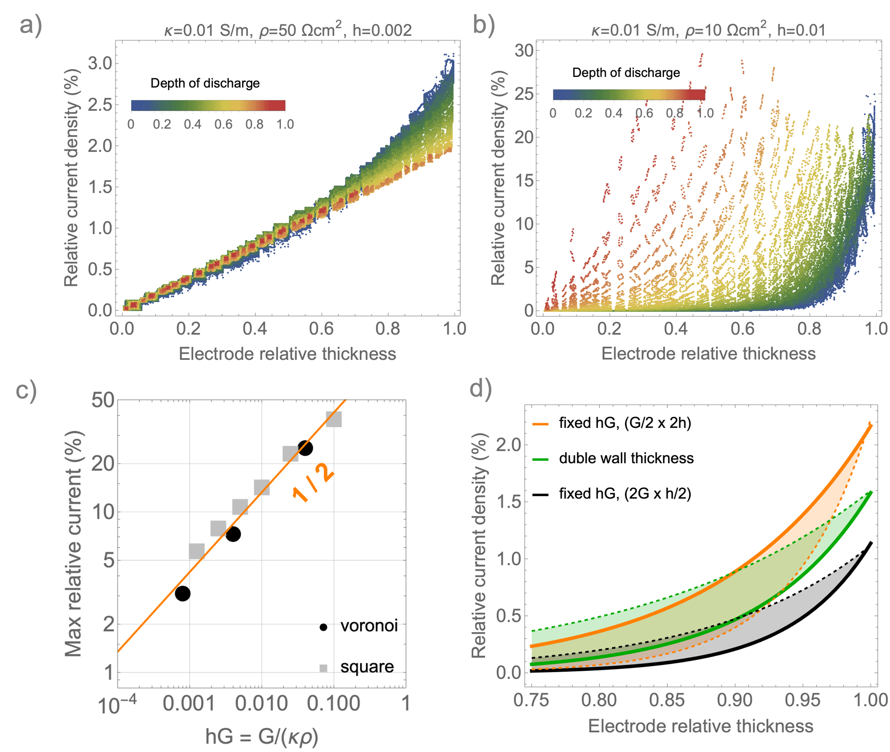
In Fig. 2 a, the sequence of four images illustrates how the deposition front moves over time, with Li-metal progressively filling the cells of the porous electrode structure. The cells closer to the separator (on the right) are filled first. The current distribution depends on the bulk conductivity of the foam and on the impedance at the Li/vapor charge-transfer interface . For this example the following values were chosen S/m and cm2 [18]. The relative current distribution through the electrode thickness is illustrated in Fig. 2 b, as a function of the depth of discharge (DOD). (At the beginning of lithiation, the state of charge is 1 and the DOD is 0.) Initially, the local deposition current density reaches the maximum value of of the applied current, and it decays exponentially away from the separator (blue points). This is due to the increase in surface area provided by the porous electrode structure. Around DOD=0.5, a steady state regime is reached with a linear distribution of the current within the electrode thickness (yellow points in Fig. 2 b). The time for establishing the linear regime depends on the conductivity and interfacial impedance. For instance, Fig. 3 a shows that a 5-fold increase in interfacial impedance (from 10 to cm2) accelerates the transition to the linear regime. A moderately larger overpotential at the interface has the effect of homogenizing the current. However, high interfacial impedance is detrimental to the battery efficiency.
Ideally if the current is uniformly distributed throughout the microstructure, the maximum value drops because the entire interface is equally active for Li-deposition. Decreasing the value of Li-ion bulk conductivity leads to higher local currents and tend to concentrate Li-deposition to a few cells at the time (Fig. 3 b).
The maximum relative current typically occurs at the beginning of lithiation and it serves as a first metric to evaluate the porous electrode design. To guide the design of resilient high-energy density systems, we need to identify what combination of material and structural properties prevents current localization at the separator interface, as this can have a negative impact on durability. To answer this question, we condense the structural and material properties into the dimensionless quantity , i.e., the product between the average grain size and the convective term (having units of 1/length).
The plot in Fig. 3 c illustrates the scaling of the peak current density at the beginning of discharge as a function of the dimensionless parameter . For Voronoi and square lattices (black and gray markers, respectively), we found that the maximum relative current scales approximately as . Only a small difference due to the specific cell geometry was observed. The two microstructures small differences in tortuosity and wall thickness. The square lattice has tortuosity 1, because the walls are straight and orthogonal to the separator.
The wall thickness does not affect the peak current at the separator, but it modifies the current decay away from the separator, as shown in Fig. 3 d (green solid and dashed line). Doubling the wall thickness favors a more homogeneous current density. The curves in Fig. 3 d refer to the conditions at the beginning of discharge. Over time, the electrode walls and previously-deposited lithium are both a pathway for Li-ion conduction, so the wall thickness has strongest impact at the beginning of lithiation. Changing the values of pore size and of the convective coefficient in such a way that their product remains constant only affects the trend of the current away from the separator, but not its peak value. The orange and black lines in Fig. 3 d indicate that decreasing the pore size is generally a good strategy to diffuse plating over a larger area.
Fig. 3 c suggests that reducing the average cell size and increasing Li-ion conductivity both contribute to lowering . This result is intuitive, however modeling allows for quantitative metrics in design and material selection. This analysis show that the requirement for pore-size distribution depends on the conductivity of the solid-electrolyte material. For highly conductive solid-electrolytes like LLZO ( mS/cm), if the average pore diameter is m [41] and interfacial impedance in the order or cm2, the local maximum current density is about 5% of the global current density. This significant reduction in current explains why mesoscale architectures can be effective in improving the cycle life of solid-state batteries with Li-metal, if the solid-electrolyte material is highly conductive. The results in Fig. 2 and Fig. 3 indicate that the local electrochemical conditions change significantly with the SE properties and it is difficult to engineer the microstructure without an accurate model.
4 Discussion
A mixed-conducting foam is investigated as a method to provide structure and resilience to high-energy density solid-state batteries with a Li-metal anode. The porous electrode structure greatly expands the surface area of the charge-transfer interface, reducing the local current density to a fraction of the applied planar current. The anode microstructure provides a conductive scaffold that maintains accessibility of active materials during charge and discharge With closed cells, the deposition front is confined within the cells, preventing dendrites from puncturing the separator and shorting the cell. If the deposition front becomes unstable dendrites tend to grow inward rather than in the direction of the separator. Nevertheless, it is currently unknown whether tension will be imposed onto the porous structure as the cell become full of lithium. This may result in a failure mode that we have not treated here. If a filled pore causes rupture of the matrix, it would not have an effect on capacity, but it would increase tortuosity and potentially create a pathway for dendrite growth in the direction of the separator.
Surface irregularities in the boundary layer can be included to study the electrochemical conditions for their amplification, and predict the velocity of dendrite propagation. The adaptive re-meshing features make this model well equipped to study whether the growing interface is stable or not. These effects are difficult to embed in a commercial finite element software, as they require changes in the topology frequently during the simulation.
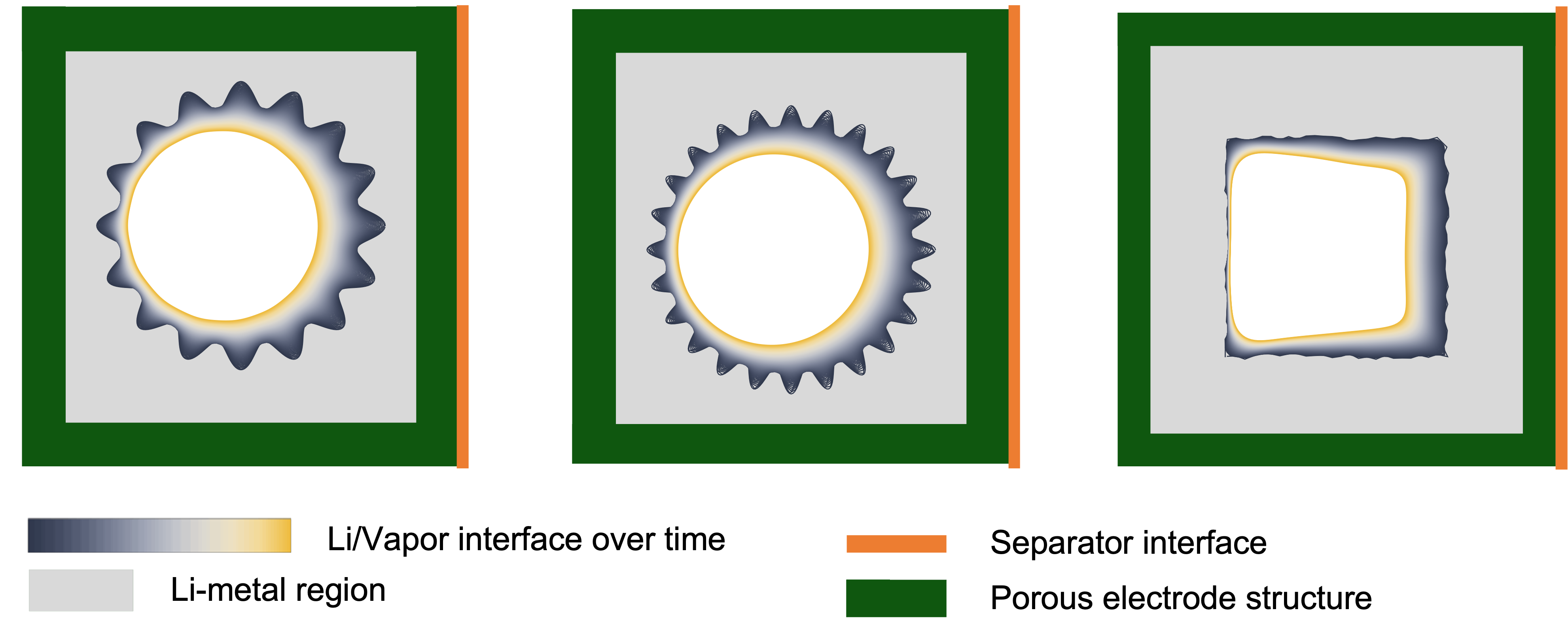
A stability analyses of the Li/Vapor interface was carried out, with some of the results shown in Fig. 4. In the case of the left and center image a sinusoidal boundary is assumed at the beginning of the simulation. Driven by the local electric field, lithium tends to fill the grooves because the current density is higher in the regions of higher curvature. The amplitude of the instability decreases over time, and the interface turns into a circle (marked in yellow in Fig. 4). The circle is off-centered with respect to the square lattice because the current is higher towards the separator (marked by the orange boundary in Fig. 4). Finally, a rough interface was generated by random displacement of the points along a square boundary, as shown on the right image of Fig. 4. Also in this case, the instability decays over time and the Li-/Vapor interface becomes smooth.
These analyses indicated that Li-dendrite growth can be suppressed by microstructural design. However, considerations of mechanical robustness should be taken into account. Failure mechanisms originated from surface flaws and from the pressure exerted on the surrounding walls as the pores are filled with lithium remain to be investigated. This requires combining deposition front tracking (presented here) with fracture mechanics, while capturing the constitutive behavior of Li-metal and of scaffold material to accurately predict stress. Analyses of the mechanical response will allow to optimize the electrode microstructure for both conductivity and resilience.
5 Conclusions
The model suggests that a porous electrode matrix may provide means to reduce shorting by confining Li plating into pores. During discharging, Li plating proceeds inwards to fill the pore. The simulation suggest that the growth is morphologically stable–it is possible that deleterious effects of dendrite growth might be avoided by microstructural design of the electrode matrix.
The capacity of the battery is determined by the availability of pore volume. However, the kinetics of charging are affected by the tortuosity of the matrix and the surface area to volume ratio of the pores. Simulation provides scaling approaches to determine what features of a porous electrode are the most important, and how to tune the design to promote uniform current distribution throughout the electrode thickness.
Author Contributions
GB conceived the presented idea and took the lead in writing the manuscript. GB and WCC developed modeling framework. TS contributed ideas on fabrication requirements and economic aspects of the battery market. MB advised on the modeling approach. All authors discussed the results and contributed to the final manuscript.
References
- [1] Jing Chen, Jiawei Wu, Xiaodong Wang, An’an Zhou, and Zhenglong Yang. Research progress and application prospect of solid-state electrolytes in commercial lithium-ion power batteries. Energy Storage Materials, 35:70–87, 2021.
- [2] Daxian Cao, Xiao Sun, Qiang Li, Avi Natan, Pengyang Xiang, and Hongli Zhu. Lithium dendrite in all-solid-state batteries: Growth mechanisms, suppression strategies, and characterizations. Matter, 3(1):57–94, 2020.
- [3] Xinyou Ke, Yan Wang, Liming Dai, and Chris Yuan. Cell failures of all-solid-state lithium metal batteries with inorganic solid electrolytes: Lithium dendrites. Energy Storage Materials, 33:309–328, 2020.
- [4] Eric Kazyak, Regina Garcia-Mendez, William S. LePage, Asma Sharafi, Andrew L. Davis, Adrian J. Sanchez, Kuan-Hung Chen, Catherine Haslam, Jeff Sakamoto, and Neil P. Dasgupta. Li penetration in ceramic solid electrolytes: Operando microscopy analysis of morphology, propagation, and reversibility. Matter, 2(4):1025–1048, 2020.
- [5] Lukas Porz, Tushar Swamy, Brian W. Sheldon, Daniel Rettenwander, Till Frömling, Henry L. Thaman, Stefan Berendts, Reinhard Uecker, W. Craig Carter, and Yet-Ming Chiang. Mechanism of lithium metal penetration through inorganic solid electrolytes. Advanced Energy Materials, 7(20):1701003, 2017.
- [6] Tushar Swamy, Richard Park, Brian W. Sheldon, Daniel Rettenwander, Lukas Porz, Stefan Berendts, Reinhard Uecker, W. Craig Carter, and Yet-Ming Chiang. Lithium metal penetration induced by electrodeposition through solid electrolytes: Example in single-crystal li6la3zrtao12garnet. Journal of The Electrochemical Society, 165(16):A3648–A3655, 2018.
- [7] Duo Zhang, Alvin Dai, Min Wu, Kang Shen, Teng Xiao, Guangya Hou, Jun Lu, and Yiping Tang. Lithiophilic 3d porous cuzn current collector for stable lithium metal batteries. ACS Energy Letters, 5(1):180–186, 2020.
- [8] Qi Li, Shoupu Zhu, and Yingying Lu. 3d porous cu current collector/li-metal composite anode for stable lithium-metal batteries. Advanced Functional Materials, 27(18):1606422, 2017.
- [9] Shengxuan Lin, Yifan Wang, Yuhang Chen, Zihe Cai, Jiajia Xiao, Tahir Muhmood, and Xiaobin Hu. Dendrite-free and ultra-long-life lithium metal anode enabled via a three-dimensional ordered porous nanostructure. ACS Applied Materials & Interfaces, 13(35):41744–41752, 2021.
- [10] Chengbin Jin, Ouwei Sheng, Jianmin Luo, Huadong Yuan, Cong Fang, Wenkui Zhang, Hui Huang, Yongping Gan, Yang Xia, Chu Liang, Jun Zhang, and Xinyong Tao. 3d lithium metal embedded within lithiophilic porous matrix for stable lithium metal batteries. Nano Energy, 37:177–186, 2017.
- [11] Shaomao Xu, Dennis W. McOwen, Chengwei Wang, Lei Zhang, Wei Luo, Chaoji Chen, Yiju Li, Yunhui Gong, Jiaqi Dai, Yudi Kuang, Chunpeng Yang, Tanner R. Hamann, Eric D. Wachsman, and Liangbing Hu. Three-dimensional, solid-state mixed electron–ion conductive framework for lithium metal anode. Nano Letters, 18(6):3926–3933, 2018.
- [12] Dennis W. McOwen, Shaomao Xu, Yunhui Gong, Yang Wen, Griffin L. Godbey, Jack E. Gritton, Tanner R. Hamann, Jiaqi Dai, Gregory T. Hitz, Liangbing Hu, and Eric D. Wachsman. 3d-printing electrolytes for solid-state batteries. Advanced Materials, 30(18):1707132, 2018.
- [13] Jonghyeok Yun, Beom-Kyeong Park, Eun-Seo Won, Seung Hyun Choi, Hyon Chol Kang, Jung Ho Kim, Min-Sik Park, and Jong-Won Lee. Bottom-up lithium growth triggered by interfacial activity gradient on porous framework for lithium-metal anode. ACS Energy Letters, 5(10):3108–3114, 2020.
- [14] Hailong Qiu, Tianyu Tang, Muhammad Asif, Xiaoxiao Huang, and Yanglong Hou. 3d porous cu current collectors derived by hydrogen bubble dynamic template for enhanced li metal anode performance. Advanced Functional Materials, 29(19):1808468, 2019.
- [15] Yuhwan Hyeon, Jaewoo Lee, Hamzeh Qutaish, Sang A Han, Seung Hyun Choi, Sung Won Moon, Min-Sik Park, Dongmok Whang, and Jung Ho Kim. Lithium metal storage in zeolitic imidazolate framework derived nanoarchitectures. Energy Storage Materials, 33:95–107, 2020.
- [16] Shu-Hua Wang, Ya-Xia Yin, Tong-Tong Zuo, Wei Dong, Jin-Yi Li, Ji-Lei Shi, Chang-Huan Zhang, Nian-Wu Li, Cong-Ju Li, and Yu-Guo Guo. Stable li metal anodes via regulating lithium plating/stripping in vertically aligned microchannels. Advanced Materials, 29(40):1703729, 2017.
- [17] Chengzhi Wang, Aoxuan Wang, Lingxiao Ren, Xuze Guan, Donghong Wang, Anping Dong, Chanyuan Zhang, Guojie Li, and Jiayan Luo. Controlling li ion flux through materials innovation for dendrite-free lithium metal anodes. Advanced Functional Materials, 29(49):1905940, 2019.
- [18] Eongyu Yi, Hao Shen, Stephen Heywood, Judith Alvarado, Dilworth Y. Parkinson, Guoying Chen, Stephen W. Sofie, and Marca M. Doeff. All-solid-state batteries using rationally designed garnet electrolyte frameworks. ACS Applied Energy Materials, 3(1):170–175, 2020.
- [19] Yao Zhao, Shuaiguo Hao, Li Su, Zhipeng Ma, and Guangjie Shao. Hierarchical cu fibers induced li uniform nucleation for dendrite-free lithium metal anode. Chemical Engineering Journal, 392:123691, 2020.
- [20] Wanfeng Yang, Jiawei Wang, Wensheng Ma, Chaoqun Dong, Guanhua Cheng, and Zhonghua Zhang. Free-standing cuo nanoflake arrays coated cu foam for advanced lithium ion battery anodes. Journal of Power Sources, 333:88–98, 2016.
- [21] Gang Zhang, Bin Deng, Quan yao Liu, Hua Yang, Mao xiang Jing, Shahid Hussain, and Tahani Saad AlGarni. Enhanced areal specific capacity and energy density of solid-state lithium battery by using porous aluminum foam. Journal of Energy Storage, 33:102167, 2021.
- [22] R Edwin Garcıa, Yet-Ming Chiang, W Craig Carter, Pimpa Limthongkul, and Catherine M Bishop. Microstructural modeling and design of rechargeable lithium-ion batteries. Journal of The Electrochemical Society, 152(1):A255, 2004.
- [23] Giovanna Bucci, Tushar Swamy, Yet-Ming Chiang, and W Craig Carter. Modeling of internal mechanical failure of all-solid-state batteries during electrochemical cycling, and implications for battery design. Journal of Materials Chemistry A, 5(36):19422–19430, 2017.
- [24] Davide Grazioli, Marco Magri, and Alberto Salvadori. Computational modeling of li-ion batteries. Computational Mechanics, 58(6):889–909, 2016.
- [25] Giovanna Bucci, Tushar Swamy, Sean Bishop, Brian W Sheldon, Yet-Ming Chiang, and W Craig Carter. The effect of stress on battery-electrode capacity. Journal of The Electrochemical Society, 164(4):A645, 2017.
- [26] Giovanna Bucci, Brandon Talamini, Ananya Renuka Balakrishna, Yet-Ming Chiang, and W Craig Carter. Mechanical instability of electrode-electrolyte interfaces in solid-state batteries. Physical Review Materials, 2(10):105407, 2018.
- [27] Anja Bielefeld, Dominik A Weber, and Jürgen Janek. Microstructural modeling of composite cathodes for all-solid-state batteries. The journal of physical chemistry C, 123(3):1626–1634, 2018.
- [28] Benedikt Prifling, Daniel Westhoff, Denny Schmidt, Henning Markoetter, Ingo Manke, Volker Knoblauch, and Volker Schmidt. Parametric microstructure modeling of compressed cathode materials for li-ion batteries. Computational Materials Science, 169:109083, 2019.
- [29] Martin Finsterbusch, Timo Danner, Chih-Long Tsai, Sven Uhlenbruck, Arnulf Latz, and Olivier Guillon. High capacity garnet-based all-solid-state lithium batteries: fabrication and 3d-microstructure resolved modeling. ACS applied materials & interfaces, 10(26):22329–22339, 2018.
- [30] David E Stephenson, Bryce C Walker, Cole B Skelton, Edward P Gorzkowski, David J Rowenhorst, and Dean R Wheeler. Modeling 3d microstructure and ion transport in porous li-ion battery electrodes. Journal of The Electrochemical Society, 158(7):A781, 2011.
- [31] Adam A Wheeler, Bruce T Murray, and Robert J Schaefer. Computation of dendrites using a phase field model. Physica D: Nonlinear Phenomena, 66(1-2):243–262, 1993.
- [32] Alain Karma and Wouter-Jan Rappel. Phase-field model of dendritic sidebranching with thermal noise. Physical review E, 60(4):3614, 1999.
- [33] Toshio Suzuki, Machiko Ode, Seong Gyoon Kim, and Won Tae Kim. Phase-field model of dendritic growth. Journal of Crystal Growth, 237:125–131, 2002.
- [34] Ingo Steinbach. Phase-field models in materials science. Modelling and simulation in materials science and engineering, 17(7):073001, 2009.
- [35] Zijian Hong and Venkatasubramanian Viswanathan. Phase-field simulations of lithium dendrite growth with open-source software. ACS Energy Letters, 3(7):1737–1743, 2018.
- [36] Jiawei Zhang, Yuanpeng Liu, Changguo Wang, and Huifeng Tan. An electrochemical-mechanical phase field model for lithium dendrite. Journal of The Electrochemical Society, 168(9):090522, 2021.
- [37] Qiao Wang, Geng Zhang, Yajie Li, Zijian Hong, Da Wang, and Siqi Shi. Application of phase-field method in rechargeable batteries. npj Computational Materials, 6(1):1–8, 2020.
- [38] Liting Gao and Zhansheng Guo. Phase-field simulation of li dendrites with multiple parameters influence. Computational Materials Science, 183:109919, 2020.
- [39] Lei Chen, Hao Wei Zhang, Lin Yun Liang, Zhe Liu, Yue Qi, Peng Lu, James Chen, and Long-Qing Chen. Modulation of dendritic patterns during electrodeposition: A nonlinear phase-field model. Journal of Power Sources, 300:376–385, 2015.
- [40] Chih-Hung Chen and Chun-Wei Pao. Phase-field study of dendritic morphology in lithium metal batteries. Journal of Power Sources, 484:229203, 2021.
- [41] Hao Shen, Eongyu Yi, Stephen Heywood, Dilworth Y. Parkinson, Guoying Chen, Nobumichi Tamura, Stephen Sofie, Kai Chen, and Marca M. Doeff. Scalable freeze-tape-casting fabrication and pore structure analysis of 3d llzo solid-state electrolytes. ACS Applied Materials & Interfaces, 12(3):3494–3501, 2020.
- [42] Benjamin Delattre, Ruhul Amin, Jonathan Sander, Joël De Coninck, Antoni P. Tomsia, and Yet-Ming Chiang. Impact of pore tortuosity on electrode kinetics in lithium battery electrodes: Study in directionally freeze-cast LiNi0.8co0.15al0.05o2(NCA). Journal of The Electrochemical Society, 165(2):A388–A395, 2018.
- [43] Ruhul Amin, Benjamin Delattre, Antoni P. Tomsia, and Yet-Ming Chiang. Electrochemical characterization of high energy density graphite electrodes made by freeze-casting. ACS Applied Energy Materials, 1(9):4976–4981, 2018.
- [44] Linsen Li, Randall M. Erb, Jiajun Wang, Jun Wang, and Yet-Ming Chiang. Fabrication of low-tortuosity ultrahigh-area-capacity battery electrodes through magnetic alignment of emulsion-based slurries. Advanced Energy Materials, 9(2):1802472, 2019.