Electrically tunable Berry curvature and strong light-matter coupling in birefringent perovskite microcavities at room temperature
Abstract
The field of spinoptronics is underpinned by good control over photonic spin-orbit coupling in devices that possess strong optical nonlinearities. Such devices might hold the key to a new era of optoelectronics where momentum and polarization degrees-of-freedom of light are interwoven and interfaced with electronics. However, manipulating photons through electrical means is a daunting task given their charge neutrality and requires complex electro-optic modulation of their medium. In this work, we present electrically tunable microcavity exciton-polariton resonances in a Rashba-Dresselhaus spin-orbit coupling field at room temperature. We show that a combination of different spin orbit coupling fields and the reduced cavity symmetry leads to tunable formation of Berry curvature, the hallmark of quantum geometrical effects. For this, we have implemented a novel architecture of a hybrid photonic structure with a two-dimensional perovskite layer incorporated into a microcavity filled with nematic liquid crystal. Our work interfaces spinoptronic devices with electronics by combining electrical control over both the strong light-matter coupling conditions and artificial gauge fields.
There has been surging interest of the condensed matter and solid state communities in generating artificial gauge fields across various platforms as means to describe particle properties [1] such as cold atoms [2, 3, 4, 5], photonic materials [6, 7], acoustics [8], mechanical systems [9], and exciton-polariton cavities [10, 11, 12]. Gauge fields play an important role in topological properties of matter [13, 14] and can be intimately linked [15] to a fundamental band property known as Berry curvature [16] quantifying the topological invariants of the system. The Berry curvature gives rise to an anomalous velocity term in a wavepacket’s motion responsible for the Hall current [17] and also the quantum Hall effect [18], with important implications in electronic transport [19].
In particular, artificial non-Abelian gauge potentials give rise to effective spin orbit coupling (SOC) of particles which has seen a lot of investigation recently in optics [20, 21, 22, 12]. SOC forms an important ingredient in the field of spintronics [23] and its optical analogue spinoptronics based on cavity exciton-polaritons [24, 25] seeking to exploit the mixture of internal (spin or polarization) and external (momentum) degrees of freedom for information processing. Exciton-polaritons (from here on just "polaritons") arise in the strong light-matter coupling regime as mixed states of microcavity photons and excitons [26]. They combine small effective photonic mass ( of the electron mass) with strong nonlinear effects [27] and sensitivity to external fields provided by their excitonic matter component. Moreover, they present an unique opportunity over photonic systems to study nontrivial band geometry with formation of Berry curvature [11, 28] and topological effects [29, 30, 31, 32, 33].
The most well known photonic SOC in microcavities is the splitting of transverse electric and transverse magnetic (i.e., TE-TM splitting) cavity photon modes [34]. This leads to a double winding effective magnetic field in the cavity plane which grows quadratically in the photon in-plane momentum [35]. Recently, photonic analogue of the electronic Dresselhaus [36], and Rashba-Dresselhaus [37, 38] SOCs have been realized in microcavities. For the case of cavities that host both Rashba-Dresselhaus (RD) SOC and TE-TM splitting it has been shown theoretically that reducing the cavity symmetry could form local concentrations of Berry curvature [39] without the need to break time reversal symmetry through external magnetic fields acting on the excitonic component of polaritons [40, 41, 11] or nonzero optical activity for the photons [42, 28].
In this work we present a method to electrically tune photonic Berry curvature in the strong light-matter coupling regime. Our optical system is composed of a liquid crystal (LC) cavity where both RD SOC and TE-TM splitting effects of the cavity photons are inherited in the emerging exciton-polariton modes due to an additional cavity embedded perovskite layer. The strongly bound perovskite excitons allow observation of strong coupling at room temperature with high quantum yield and nonlinear effects up to four orders of magnitude higher than in other photonic systems [12, 43], and thus present a good material to be interfaced with LCs. Due to the high birefringence and electric permittivity anisotropy of LCs, making them sensitive to external electric fields, we achieve unprecedented electric control over an emerging polaritonic Berry curvature through the specially synthesized photonic SOC and reduced cavity symmetry.
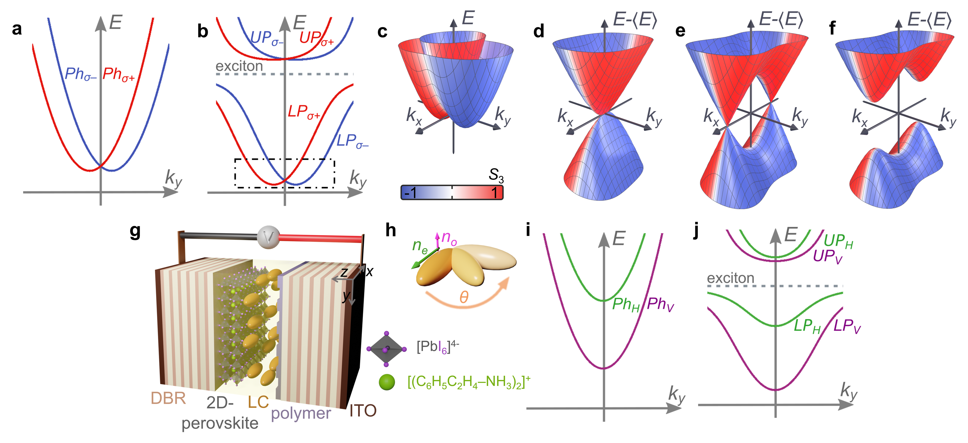
A cross section of the photonic RD dispersion in the cavity () plane is schematically shown in Fig. 1a depicting two opposite circularly polarized valleys in analogy with spin 1/2 systems. When the photons become strongly coupled with the perovskite excitons a characteristic anticrossing behaviour occurs shown in Fig. 1b where the low energy polariton modes (within the dot-dashed square box) adopt approximately the same dispersion as that of the photons (Fig. 1a). A surface plot of the polariton dispersion at low momenta is shown in Fig. 1c. A single degeneracy point at normal incidence () is highlighted in the RD polariton dispersion (Fig. 1d) where we have subtracted the dispersion from its mean . When TE-TM splitting and an additional uniform in-plane effective magnetic field are present the RD degeneracy point morphs into two Dirac cones with degeneracy points known as diabolical points (Fig. 1e) [33, 11, 42, 44, 45]. The rapidly whirling RD SOC field around these points leads to a topologically trivial gap opening (Fig. 1f) when an additional perpendicular effective magnetic field is introduced to break the inversion symmetry of the system with subsequent formation of a Berry curvature dipole (as shown later in the text).
.1 Strong light-matter coupling
The microcavity consists of two distributed Bragg reflectors (DBRs) facing each other with an embedded 60 nm thick polycrystalline 2D phenylethylammonium lead iodide (PEAI) perovskite (C6H5C2H4NH3)2PbI4 (hereafter termed: PEPI), shown schematically in Fig. 1g. The perovskite polycrystalline thin film was prepared on one of the DBR inner sides using a spin-coating method [46]. The cavity structure was designed to enhance the photonic field at the position of the perovskite layer. The cavity was also filled with a highly birefringent nematic LC which acts as an uniaxial medium with ordinary and extraordinary refractive indices ( [47]). The voltage applied to transparent electrodes (made of Indium Tin Oxide - ITO) rotates the molecular director, hence the direction of the optical axis of the LC medium, by an angle in the - plane (see Fig. 1h). This enables direct control over the cavity effective refractive indices. Throughout the paper we will refer to the Stokes parameters of the emitted cavity light (analogous to the polariton pseudospin) as and and corresponding to intensities of horizontal (), vertical (), diagonal (), antidiagonal (), right-hand circular () and left-hand circular () polarized light.
The alignment of the LC molecules inside the cavity at zero voltage is determined by an ordering polymer layer rubbed along the (H) direction as shown schematically in Fig. 1g. Consequently, the bare photon dispersion in the linear horizontal-vertical (H-V) polarization basis shown in Fig. 1i displays strongly split bands described by the Hamiltonian:
| (1) |
where is the in-plane momentum. Here, describes an effective photonic SOC coming from both cavity TE-TM splitting [34] and the LC anisotropy [37],
| (2) |
Physically, this operator introduces direction dependent modification to the effective masses of linearly polarized modes. When it realizes the conventional TE-TM splitting [48]. Finally, describes uniform splitting between H and V polarized modes (sometimes referred as - splitting) which can be directly controlled in the experiment through the voltage applied to the ITO electrodes on the cavity, where the electric field drives the molecular director, hence the optical axis and changes the effective refractive indices for the H polarized mode. We note that all coefficients in Eqs. (1) and (2) depend on but not as strongly as [37]. We do not consider non-Hermitian effects which are weak in our system and only relevant to the physics of exceptional points [33, 49, 50] which is beyond the scope of our study.
When an exciton resonance, with energy , from the perovskite layer is introduced to the cavity (dashed horizontal line in Fig. 1j) the linearly polarized photonic modes coherently couple to excitons at a rate defined by the Rabi energies . The strongly coupled system can be described by a coupled-oscillators model represented by a Hamiltonian:
| (3) |
The four polariton eigenmodes are shown in Figure 1j, exhibiting characteristic anticrossing behaviour, and labelled as upper (UPH,V) and lower polaritons (LPH,V).
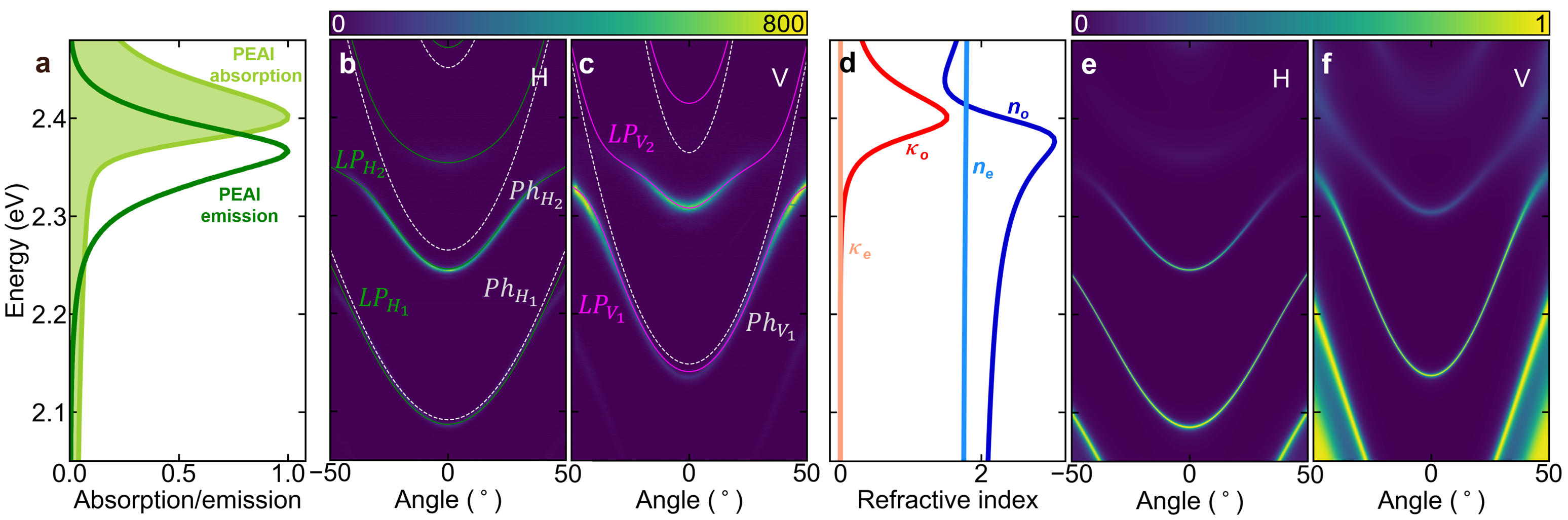
The strong coupling regime in our structure is illustrated in Fig. 2. The strong emission (dark green line) and absorption (light green line) spectra of a thin PEPI layer without the cavity are shown in Fig. 2a. The maximum of the spectra overlap is at 2.38 eV, which corresponds to the most effective emission and reabsorption processes. The emission spectra from our cavity at room temperature at zero voltage (i.e., ) are presented in Fig. 2b,c evidencing strong emission from H-V polariton modes. The characteristic anti-crossing between the excitonic resonance and the cavity photon modes is visible in the emission spectra at high emission angles.
Our measurements are compared with the solutions of Eq. (3) plotted with solid lines in Fig. 2b,c (see Methods). The white dashed lines indicate the fitted bare photonic branches. Extracted Rabi energies for H and V polarized modes are: meV and meV. This difference between the Rabi energies is due to different optical paths for the two linear polarizations (difference in the LC refractive indices and ).
We also performed numerical simulations on the optical properties of our cavity using the Berreman matrix method. For this purpose, the real and imaginary parts of the ordinary and extraordinary refractive indices and , respectively, were obtained from ellipsometric measurements and are presented in Fig. 2d. We observe a slight birefringence of the polycrystalline perovskite in the -axis direction (perpendicular to the cavity plane). The simulated angle-resolved transmission spectra are shown in Fig. 2e,f. The theoretical result is fully consistent with the experiment. The higher energy modes (above 2.39 eV) are not visible in the experimental spectra due to the strong absorption of the perovskite in this spectral range.
.2 Rashba-Dresselhaus polaritons
By rotating the molecular director of the LC with applied voltage, photonic modes of different polarization and parities become mixed and form a RD SOC dispersion relation [37]. In this case, any effective in-plane fields are minimal and the photonic modes are circularly polarized, forming a dispersion depicting two shifted valleys of opposite circular polarization (like shown in Fig. 1a). In this regime, the photonic Hamiltonian can be written:
| (4) |
where is the strength of the RD SOC. It is worth noting that in this low-energy regime polariton and photon lasing was recently demonstrated[51, 52].
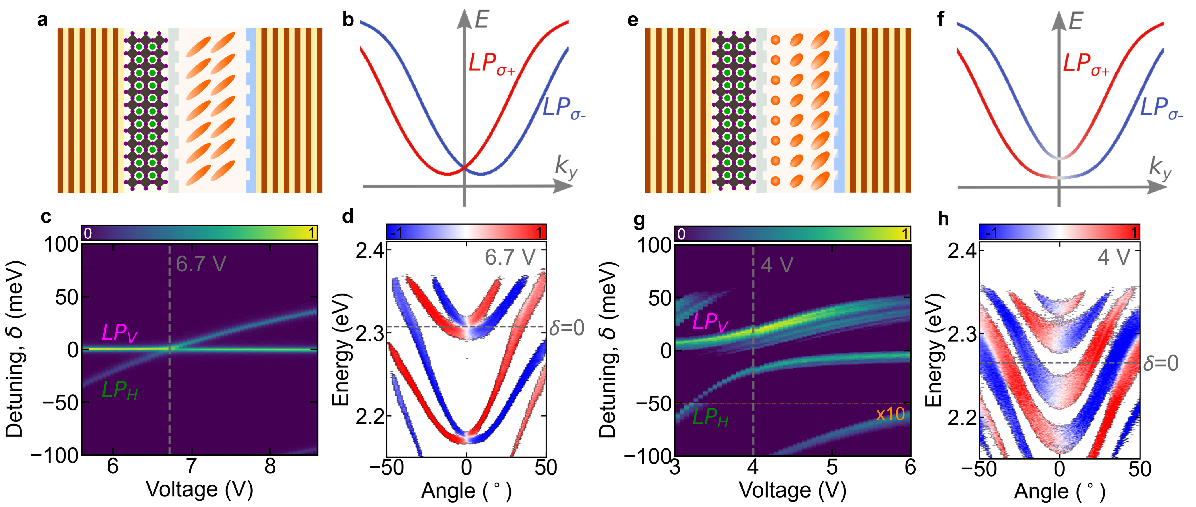
The polariton RD SOC regime is illustrated in Fig. 3 for two different cavity types. In Fig. 3a-d we show the effects of RD SOC photonic modes coupled to the excitonic resonance. Here, the LC molecules are initially (at 0 V) oriented by two parallel rubbing polymer layers as shown in Fig. 3a. The degeneracy point in the RD dispersion (see Fig. 3b at ) is sensitive to H-V splitting that can be directly controlled through the applied voltage [i.e., ]. We measured the cavity PL as a function of applied voltage at , shown in Figure 3c, and observed the crossing of two polariton modes at around 6.7 V. This crossing point corresponds to the degeneracy point in the RD polariton dispersion, also evidenced through the measured component shown in Fig. 3d.
.3 Berry curvature dipole
Synthesizing polaritonic Berry curvature in optical cavities is a challenging task since it requires breaking of time-reversal symmetry through external magnetic fields acting on the excitonic component [40, 41, 11, 28], or nonzero optical activity for the photons [42]. Such chiral terms open a gap at the diabolical points in the polariton dispersion, corresponding to a Dirac cone intersection [53, 12, 54, 44], where the TE-TM SOC field from and the uniform field cancel each other out. Indeed, with the polariton modes are linearly polarized with a rapidly changing in-plane SOC field winding around the Dirac cones (i.e., the polariton pseudospin winds around the – plane when going around the diabolical point [11, 12]). It is worth noting that when non-Hermitian terms are present these diabolical points become exceptional points which expand to degeneracy lines (Fermi arcs) when polarization-dependent losses are present [55, 56, 33, 50].
Interestingly, when RD SOC is present it introduces and additional rapidly varying field around the Dirac cones manifested in the strong component in the polariton dispersion. Practically, the diabolical points can only appear along the () axis where the RD field vanishes (see Fig. 1e). Therefore, the RD field will only affect the SOC field around these points but it cannot open the gap. However, because of the combined TE-TM and RD SOC fields the polariton pseudospin no longer winds just in the – plane when going around the diabolical points but also around the – plane. This means that an effective magnetic field in the -direction corresponding to a finite pseudospin component will break inversion symmetry at the diabolical points and open the gap. Physically, such an effective magnetic field corresponds to splitting between the diagonal (D) and antidiagonal (AD) modes written,
| (5) |
Indeed, setting it can be shown that the presence of the breaks parity inversion symmetry where flips the photon circular polarization in the H-V basis. This leads to opening of the gap with subsequent formation of local dispersion relation describing massive Dirac particles (see Fig. 1f).
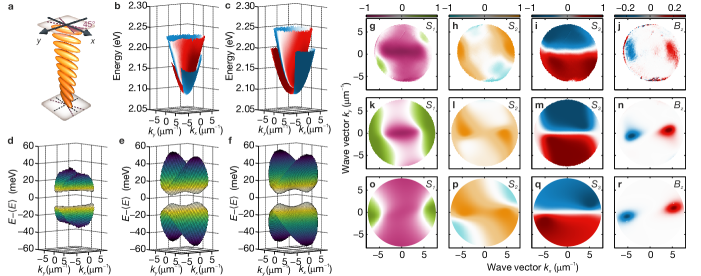
For this purpose, we have prepared a second sample with rubbing at the perovskite layer oriented at an angle of 45∘ with respect to the rubbing at the DBR surface, Fig. 3e. This results in a twisted nematic LC structure (as illustrated in Fig. 4a) which introduces a deterministic D-AD splitting. The splitting is confirmed in Fig. 3g where the PL spectrum at as a function of voltage shows a clear anticrossing. Fig. 3h shows the circular polarization degree of the corresponding angle-resolved dispersion and Fig. 3f the calculated dispersion.
The concave energy relation indicating the location of the massive Dirac cones with a clear splitting is illustrated in Fig. 4b-f. The Stokes (pseudospin) parameters in Fig. 4g-i show that at the minimum of energy-gap the and polarizations of the bands whirl around two diagonally polarized points located along . This evidences that the splitting between D and AD polarized modes in the twisted nematic configuration has opened a gap at these points. More importantly, these points are accompanied with strong concentration of polaritonic Berry curvature as measured and calculated in Fig. 4j,n,r. As time reversal symmetry is conserved in the system integral over the the Berry curvature within a single band is equal to zero, and for the second band the Berry curvature is expected to be of the opposite sign. We note that at in Fig. 4g the mode is predominantly V polarized due to the applied voltage causing some additional splitting . All of our results are in qualitative agreement with both our analytical model of Eq. (5) and Berreman simulations. Results of the analytical model in Fig. 4f were fitted to the dispersion relation obtained from Berreman matrix model (see Methods).
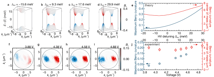
Lastly, the observed polariton Berry curvature can be electrically tuned through the parameter which is directly controlled by amplitude of external voltage applied to the cavity. Fig. 5a–e presents calculations based on Eq. (4) for varying detuning between the H-V modes. The calculated energies of the two bands are subtracted from their mean value with the Berry curvature marked by a pseudocolor scale. The Berry curvature increases with H-V detuning as the dispersion relation changes to two gapped Dirac cones exhibiting a pronounced Berry curvature. Dependence of the maximum value of Berry curvature and the center of mass position in reciprocal space is summarized in Fig. 5e, which shows that the momentum position of the Berry curvature maximum can be controlled by detuning and can be effectively switched off for negative detunings.
Those theoretical predictions can be confirmed experimentally for varying voltage applied to the cavity which directly controls detuning. Fig. 5f–i presents Berry curvature extracted from polarization-resolved transmission measurement at different voltages applied to the ITO electrodes of the cavity. At 3.88 V (Fig. 5f) corresponding to negative detuning observed value of the Berry curvatures is low, but rapidly increases for higher voltages when detuning becomes positive (Fig. 5g). Further increase of the applied voltage shifts the position of the maxima to higher momenta in reciprocal space up to the limits of the numerical aperture in the experiment (Fig. 5h,i). Experimental position and value of the polaritonic Berry curvature summarised in Fig. 5j are in good agreement with theoretical predictions of Fig. 5e and clearly demonstrate electric tunability of the band geometry in our system. The polaritonic Berry curvature in our system is tunable in a continuous manner with the amplitude of external voltage, rather than magnetic field or temperature [28].
Conclusion
In conclusion, we have presented a novel architecture for a photonic cavity heterostructure with a 2D-perovskite incorporated in a highly birefringent medium. The medium is a nematic liquid crystal that can be arranged in various ways into the cavity through proper preparation of embedded ordering layers. We firstly achieve electrically tunable strong light-matter coupling between the perovskite excitons and cavity photons as a functing of applied external electric field regime at room temperature with Rabi splitting in the order of meV. We demonstrate how the extreme birefringence coming from the liquid crystal results in exciton-polariton modes following a Rashba-Dresselhaus spin-orbit-coupling dispersion relation which opens exciting perspectives on designing nonlinear valley-optronic devices.
Second, the reduced symmetry of the cavity structure is found to open a gap at polaritonic diabolical points corresponding to Dirac cones in the cavity dispersion relation. This allows us to engineer local concentrations of Berry curvature that can be controlled through applied external voltage which has only been possible using external magnetic fields or temperature variations [28]. The importance of the Berry curvature dipole to the quantum nonlinear Hall effect [57] and rectification in polar semiconductors [58] was recently stressed in a study demonstrating its electric tunability in a monolayer WTe2 [59]. Our work therefore takes steps towards interfacing polariton spinoptronic technologies with electronics at room temperature where nontrivial geometrical properties of the polariton dispersion can be easily tuned through applied voltage. We note that both electrically pumped polariton lasers [60] and electro-optic modulated polariton topological lasers [61] are already possible at cryogenic temperatures. Moreover, with already exciting work aimed at Rashba-Dresselhaus polariton condensation [51] we expect that our platform can serve as a testbed for driven-dissipative quantum matter in unconventional artificial gauge fields.
References
- Aidelsburger et al. [2018] M. Aidelsburger, S. Nascimbene, and N. Goldman, Artificial gauge fields in materials and engineered systems, Comptes Rendus Physique 19, 394 (2018).
- Dalibard et al. [2011] J. Dalibard, F. Gerbier, G. Juzeliūnas, and P. Öhberg, Colloquium: Artificial gauge potentials for neutral atoms, Rev. Mod. Phys. 83, 1523 (2011).
- Eckardt [2017] A. Eckardt, Colloquium: Atomic quantum gases in periodically driven optical lattices, Rev. Mod. Phys. 89, 011004 (2017).
- Galitski et al. [2019] V. Galitski, G. Juzeliūnas, and I. B. Spielman, Artificial gauge fields with ultracold atoms, Physics Today 72, 38 (2019).
- Li et al. [2022] Y. Li, J. Zhang, Y. Wang, H. Du, J. Wu, W. Liu, F. Mei, J. Ma, L. Xiao, and S. Jia, Atom-optically synthetic gauge fields for a noninteracting Bose gas, Light: Science & Applications 11, 13 (2022).
- Fang et al. [2012] K. Fang, Z. Yu, and S. Fan, Realizing effective magnetic field for photons by controlling the phase of dynamic modulation, Nature Photonics 6, 782 (2012).
- Lumer et al. [2019] Y. Lumer, M. A. Bandres, M. Heinrich, L. J. Maczewsky, H. Herzig-Sheinfux, A. Szameit, and M. Segev, Light guiding by artificial gauge fields, Nature Photonics 13, 339 (2019).
- Xiao et al. [2015] M. Xiao, W.-J. Chen, W.-Y. He, and C. T. Chan, Synthetic gauge flux and Weyl points in acoustic systems, Nature Physics 11, 920 (2015).
- Abbaszadeh et al. [2017] H. Abbaszadeh, A. Souslov, J. Paulose, H. Schomerus, and V. Vitelli, Sonic Landau levels and synthetic gauge fields in mechanical metamaterials, Phys. Rev. Lett. 119, 195502 (2017).
- Gao et al. [2015] T. Gao, E. Estrecho, K. Y. Bliokh, T. C. H. Liew, M. D. Fraser, S. Brodbeck, M. Kamp, C. Schneider, S. Höfling, Y. Yamamoto, F. Nori, Y. S. Kivshar, A. G. Truscott, R. G. Dall, and E. A. Ostrovskaya, Observation of non-Hermitian degeneracies in a chaotic exciton-polariton billiard, Nature 526, 554 (2015).
- Gianfrate et al. [2020] A. Gianfrate, O. Bleu, L. Dominici, V. Ardizzone, M. D. Giorgi, D. Ballarini, G. Lerario, K. W. West, L. N. Pfeiffer, D. D. Solnyshkov, D. Sanvitto, and G. Malpuech, Measurement of the quantum geometric tensor and of the anomalous Hall drift, Nature 578, 381 (2020).
- Polimeno et al. [2021a] L. Polimeno, A. Fieramosca, G. Lerario, L. D. Marco, M. D. Giorgi, D. Ballarini, L. Dominici, V. Ardizzone, M. Pugliese, C. T. Prontera, V. Maiorano, G. Gigli, C. Leblanc, G. Malpuech, D. D. Solnyshkov, and D. Sanvitto, Experimental investigation of a non-Abelian gauge field in 2D perovskite photonic platform, Optica 8, 1442 (2021a).
- Hasan and Kane [2010] M. Z. Hasan and C. L. Kane, Colloquium: Topological insulators, Rev. Mod. Phys. 82, 3045 (2010).
- Ozawa et al. [2019] T. Ozawa, H. M. Price, A. Amo, N. Goldman, M. Hafezi, L. Lu, M. C. Rechtsman, D. Schuster, J. Simon, O. Zilberberg, and I. Carusotto, Topological photonics, Rev. Mod. Phys. 91, 015006 (2019).
- Simon [1983] B. Simon, Holonomy, the quantum adiabatic theorem, and Berry’s phase, Phys. Rev. Lett. 51, 2167 (1983).
- Berry [1984] M. V. Berry, Quantal phase factors accompanying adiabatic changes, Proceedings of the Royal Society of London. A. Mathematical and Physical Sciences 392, 45 (1984).
- Karplus and Luttinger [1954] R. Karplus and J. M. Luttinger, Hall effect in ferromagnetics, Phys. Rev. 95, 1154 (1954).
- Thouless et al. [1982] D. J. Thouless, M. Kohmoto, M. P. Nightingale, and M. den Nijs, Quantized Hall conductance in a two-dimensional periodic potential, Phys. Rev. Lett. 49, 405 (1982).
- Xiao et al. [2010] D. Xiao, M.-C. Chang, and Q. Niu, Berry phase effects on electronic properties, Rev. Mod. Phys. 82, 1959 (2010).
- Bliokh et al. [2015] K. Y. Bliokh, F. J. Rodríguez-Fortuño, F. Nori, and A. V. Zayats, Spin-orbit interactions of light, Nat. Photonics 9, 796 (2015).
- Chen et al. [2019] Y. Chen, R.-Y. Zhang, Z. Xiong, Z. H. Hang, J. Li, J. Q. Shen, and C. T. Chan, Non-Abelian gauge field optics, Nature Communications 10, 3125 (2019).
- Yang et al. [2019] Y. Yang, C. Peng, D. Zhu, H. Buljan, J. D. Joannopoulos, B. Zhen, and M. Soljačić, Synthesis and observation of non-Abelian gauge fields in real space, Science 365, 1021 (2019).
- Žutić et al. [2004] I. Žutić, J. Fabian, and S. Das Sarma, Spintronics: Fundamentals and applications, Rev. Mod. Phys. 76, 323 (2004).
- Liew et al. [2011] T. Liew, I. Shelykh, and G. Malpuech, Polaritonic devices, Physica E: Low-dimensional Systems and Nanostructures 43, 1543 (2011).
- Sanvitto and Kéna-Cohen [2016] D. Sanvitto and S. Kéna-Cohen, The road towards polaritonic devices, Nature Materials 15, 1061 (2016).
- Carusotto and Ciuti [2013] I. Carusotto and C. Ciuti, Quantum fluids of light, Rev. Mod. Phys. 85, 299 (2013).
- St-Jean et al. [2017] P. St-Jean, V. Goblot, E. Galopin, A. Lemaître, T. Ozawa, L. L. Gratiet, I. Sagnes, J. Bloch, and A. Amo, Lasing in topological edge states of a one-dimensional lattice, Nature Photonics 11, 651 (2017).
- Polimeno et al. [2021b] L. Polimeno, G. Lerario, M. D. Giorgi, L. D. Marco, L. Dominici, F. Todisco, A. Coriolano, V. Ardizzone, M. Pugliese, C. T. Prontera, V. Maiorano, A. Moliterni, C. Giannini, V. Olieric, G. Gigli, D. Ballarini, Q. Xiong, A. Fieramosca, D. D. Solnyshkov, G. Malpuech, and D. Sanvitto, Tuning of the Berry curvature in 2D perovskite polaritons, Nature Nanotechnology 16, 1349 (2021b).
- Karzig et al. [2015] T. Karzig, C.-E. Bardyn, N. H. Lindner, and G. Refael, Topological polaritons, Phys. Rev. X 5, 031001 (2015).
- Nalitov et al. [2015] A. V. Nalitov, D. D. Solnyshkov, and G. Malpuech, Polariton topological insulator, Phys. Rev. Lett. 114, 116401 (2015).
- Solnyshkov et al. [2021] D. D. Solnyshkov, G. Malpuech, P. St-Jean, S. Ravets, J. Bloch, and A. Amo, Microcavity polaritons for topological photonics [invited], Optical Materials Express 11, 1119 (2021).
- Klembt et al. [2018] S. Klembt, T. H. Harder, O. A. Egorov, K. Winkler, R. Ge, M. A. Bandres, M. Emmerling, L. Worschech, T. C. H. Liew, M. Segev, C. Schneider, and S. Höfling, Exciton-polariton topological insulator, Nature 562, 552 (2018).
- Su et al. [2021] R. Su, E. Estrecho, D. Biegańska, Y. Huang, M. Wurdack, M. Pieczarka, A. G. Truscott, T. C. H. Liew, E. A. Ostrovskaya, and Q. Xiong, Direct measurement of a non-Hermitian topological invariant in a hybrid light-matter system, Science Advances 7, eabj8905 (2021).
- Panzarini et al. [1999] G. Panzarini, L. C. Andreani, A. Armitage, D. Baxter, M. S. Skolnick, V. N. Astratov, J. S. Roberts, A. V. Kavokin, M. R. Vladimirova, and M. A. Kaliteevski, Exciton-light coupling in single and coupled semiconductor microcavities: Polariton dispersion and polarization splitting, Phys. Rev. B 59, 5082 (1999).
- Leyder et al. [2007] C. Leyder, M. Romanelli, J. P. Karr, E. Giacobino, T. C. H. Liew, M. M. Glazov, A. V. Kavokin, G. Malpuech, and A. Bramati, Observation of the optical spin Hall effect, Nat. Phys. 3, 628 (2007).
- Whittaker et al. [2021] C. E. Whittaker, T. Dowling, A. V. Nalitov, A. V. Yulin, B. Royall, E. Clarke, M. S. Skolnick, I. A. Shelykh, and D. N. Krizhanovskii, Optical analogue of Dresselhaus spin–orbit interaction in photonic graphene, Nat. Photonics 15, 193 (2021).
- Rechcińska et al. [2019] K. Rechcińska, M. Król, R. Mazur, P. Morawiak, R. Mirek, K. Łempicka, W. Bardyszewski, M. Matuszewski, P. Kula, W. Piecek, P. G. Lagoudakis, B. Piętka, and J. Szczytko, Engineering spin-orbit synthetic Hamiltonians in liquid-crystal optical cavities, Science 366, 727 (2019).
- Ren et al. [2022] J. Ren, Q. Liao, X. Ma, S. Schumacher, J. Yao, and H. Fu, Realization of exciton-mediated optical spin-orbit interaction in organic microcrystalline resonators, Laser & Photonics Reviews 16, 2100252 (2022).
- Kokhanchik et al. [2021] P. Kokhanchik, H. Sigurdsson, B. Piętka, J. Szczytko, and P. G. Lagoudakis, Photonic Berry curvature in double liquid crystal microcavities with broken inversion symmetry, Phys. Rev. B 103, L081406 (2021).
- Gutiérrez-Rubio et al. [2018] A. Gutiérrez-Rubio, L. Chirolli, L. Martín-Moreno, F. J. García-Vidal, and F. Guinea, Polariton anomalous Hall effect in transition-metal dichalcogenides, Phys. Rev. Lett. 121, 137402 (2018).
- Bleu et al. [2018] O. Bleu, D. D. Solnyshkov, and G. Malpuech, Measuring the quantum geometric tensor in two-dimensional photonic and exciton-polariton systems, Phys. Rev. B 97, 195422 (2018).
- Ren et al. [2021] J. Ren, Q. Liao, F. Li, Y. Li, O. Bleu, G. Malpuech, J. Yao, H. Fu, and D. Solnyshkov, Nontrivial band geometry in an optically active system, Nature Communications 12, 689 (2021).
- Wu et al. [2021] J. Wu, S. Ghosh, R. Su, A. Fieramosca, T. C. H. Liew, and Q. Xiong, Nonlinear parametric scattering of exciton polaritons in perovskite microcavities, Nano Letters 21, 3120 (2021).
- Spencer et al. [2021] M. S. Spencer, Y. Fu, A. P. Schlaus, D. Hwang, Y. Dai, M. D. Smith, D. R. Gamelin, and X.-Y. Zhu, Spin-orbit–coupled exciton-polariton condensates in lead halide perovskites, Science Advances 7, eabj7667 (2021).
- Bergholtz et al. [2021] E. J. Bergholtz, J. C. Budich, and F. K. Kunst, Exceptional topology of non-Hermitian systems, Rev. Mod. Phys. 93, 015005 (2021).
- Łempicka et al. [2019] K. Łempicka, M. Furman, M. Muszyński, M. Król, A. Wincukiewicz, K. Rechcińska, R. Mazur, W. Piecek, M. Kamińska, J. Szczytko, and B. Piętka, Exciton-polaritons in a tunable microcavity with 2D-perovskite, in International Photonics and OptoElectronics Meeting 2019 (OFDA, OEDI, ISST, PE, LST, TSA) (Optical Society of America, 2019) p. JW4A.66.
- Miszczyk et al. [2018] E. Miszczyk, R. Mazur, P. Morawiak, M. Mrukiewicz, W. Piecek, Z. Raszewski, P. Kula, K. Kowiorski, J. Kędzierski, and J. Zieliński, Refractive index matched liquid crystal cell for laser metrology application, Liq. Cryst. 45, 1690 (2018).
- Kavokin et al. [2005] A. Kavokin, G. Malpuech, and M. Glazov, Optical spin Hall effect, Phys. Rev. Lett. 95, 136601 (2005).
- Liao et al. [2021] Q. Liao, C. Leblanc, J. Ren, F. Li, Y. Li, D. Solnyshkov, G. Malpuech, J. Yao, and H. Fu, Experimental measurement of the divergent quantum metric of an exceptional point, Phys. Rev. Lett. 127, 107402 (2021).
- Król et al. [2021] M. Król, I. Septembre, P. Oliwa, M. Kędziora, K. Łempicka Mirek, M. Muszyński, R. Mazur, P. Morawiak, W. Piecek, P. Kula, W. Bardyszewski, P. G. Lagoudakis, D. D. Solnyshkov, G. Malpuech, B. Piętka, and J. Szczytko, Annihilation of exceptional points from different Dirac valleys in a 2D photonic system (2021), arXiv:arXiv:2112.06621 [cond-mat.mes-hall] .
- Li et al. [2021] Y. Li, X. Ma, X. Zhai, M. Gao, H. Dai, S. Schumacher, and T. Gao, Manipulate polariton condensates by Rashba-Dresselhaus effect at room temperature, arXiv e-prints , arXiv:2108.02057 (2021), arXiv:2108.02057 [cond-mat.quant-gas] .
- Muszyński et al. [2022] M. Muszyński, M. Król, K. Rechcińska, P. Oliwa, M. Kędziora, K. Łempicka-Mirek, R. Mazur, P. Morawiak, W. Piecek, P. Kula, P. G. Lagoudakis, B. Piętka, and J. Szczytko, Realizing persistent-spin-helix lasing in the regime of Rashba-Dresselhaus spin-orbit coupling in a dye-filled liquid-crystal optical microcavity, Phys. Rev. Applied 17, 014041 (2022).
- Terças et al. [2014] H. Terças, H. Flayac, D. D. Solnyshkov, and G. Malpuech, Non-Abelian gauge fields in photonic cavities and photonic superfluids, Phys. Rev. Lett. 112, 066402 (2014).
- Biegańska et al. [2021] D. Biegańska, M. Pieczarka, E. Estrecho, M. Steger, D. W. Snoke, K. West, L. N. Pfeiffer, M. Syperek, A. G. Truscott, and E. A. Ostrovskaya, Collective excitations of exciton-polariton condensates in a synthetic gauge field, Phys. Rev. Lett. 127, 185301 (2021).
- Richter et al. [2017] S. Richter, T. Michalsky, C. Sturm, B. Rosenow, M. Grundmann, and R. Schmidt-Grund, Exceptional points in anisotropic planar microcavities, Phys. Rev. A 95, 023836 (2017).
- Richter et al. [2019] S. Richter, H.-G. Zirnstein, J. Zúñiga Pérez, E. Krüger, C. Deparis, L. Trefflich, C. Sturm, B. Rosenow, M. Grundmann, and R. Schmidt-Grund, Voigt exceptional points in an anisotropic ZnO-based planar microcavity: Square-root topology, polarization vortices, and circularity, Phys. Rev. Lett. 123, 227401 (2019).
- Sodemann and Fu [2015] I. Sodemann and L. Fu, Quantum nonlinear Hall effect induced by Berry curvature dipole in time-reversal invariant materials, Phys. Rev. Lett. 115, 216806 (2015).
- Ideue et al. [2017] T. Ideue, K. Hamamoto, S. Koshikawa, M. Ezawa, S. Shimizu, Y. Kaneko, Y. Tokura, N. Nagaosa, and Y. Iwasa, Bulk rectification effect in a polar semiconductor, Nature Physics 13, 578 (2017).
- Xu et al. [2018] S.-Y. Xu, Q. Ma, H. Shen, V. Fatemi, S. Wu, T.-R. Chang, G. Chang, A. M. M. Valdivia, C.-K. Chan, Q. D. Gibson, J. Zhou, Z. Liu, K. Watanabe, T. Taniguchi, H. Lin, R. J. Cava, L. Fu, N. Gedik, and P. Jarillo-Herrero, Electrically switchable Berry curvature dipole in the monolayer topological insulator WTe2, Nature Physics 14, 900 (2018).
- Schneider et al. [2013] C. Schneider, A. Rahimi-Iman, N. Y. Kim, J. Fischer, I. G. Savenko, M. Amthor, M. Lermer, A. Wolf, L. Worschech, V. D. Kulakovskii, I. A. Shelykh, M. Kamp, S. Reitzenstein, A. Forchel, Y. Yamamoto, and S. Höfling, An electrically pumped polariton laser, Nature 497, 348 (2013).
- Gagel et al. [2022] P. Gagel, T. H. Harder, S. Betzold, O. A. Egorov, J. Beierlein, H. Suchomel, M. Emmerling, A. Wolf, U. Peschel, S. Höfling, C. Schneider, and S. Klembt, Electro-optical switching of a topological polariton laser, ACS Photonics 9, 405 (2022).
- Schubert [1996] M. Schubert, Polarization-dependent optical parameters of arbitrarily anisotropic homogeneous layered systems, Phys. Rev. B 53, 4265 (1996).
Methods
Preparation of liquid crystal microcavity with 2D-perovskite. The studied microcavity structure consists of two distributed Bragg reflectors (DBRs) made of 6 SiO2/TiO2 (SiO2 top layer) pairs with maximum reflectance at 520 nm. DBRs grown on glass substrates with ITO electrodes. The surface of the dielectric mirror was cleaned with isopropanol and acetone to remove organic residues from the surface. It was then activated in an oxygen plasma, thanks to which the 2D-perovskite crystallization precursor solution adhered better to the substrate. Due to the activation of the DBRs surface, the 2D-perovskite crystallization precursor solution adheres better to the substrate. The precursor solution was prepared in a glove box under an argon atmosphere as follows: phenethylammonium iodide (PEAI) was mixed with lead iodide (PbI2) in a stoichiometric 2:1 molar ratio and dissolved in N,N-dimethylformamide (DMF) (mass percent: 10%). The solution was stirred for 4 h at 50 ∘C. All reagents were purchased from Sigma Aldrich. 40 l of solution containing PEAI and PbI2 was spin-coated in air on a dielectric mirror with rotation speed of 2,000 rpm for 30 sec. Approximately 60 nm thick 2D-layered polycrystalline lead iodide perovskite [(C6H5(CH2)2NH3)2PbI4] was obtained upon solvent evaporation on the hotplate for 1 minute at 100 ∘C.
There were two types of microcavities as shown in (Fig. 3). For these samples, the preparation of the dielectric mirror coated with 2D-polycrystalline perovskite was the same, as described above. In the case of the first sample (Fig. 3a), the bottom dielectric mirror with perovskite was spin-coated with a thin, protective layer (50 nm thick) of PMMA with a 3% methoxybenzene solution. The upper dielectric mirror was covered with a structured polymer orienting layer of SE-130. The space between the DBRs is filled with highly birefringent liquid crystal of . Both mirrors were rubbed to obtain homogeneous LC orientation within the cavity. The total thickness of this liquid crystal cavity with was approximately 3 m. The second sample type was similar in design to the first one, but the PMMA layer on the dielectric mirror was arranged at an angle of 45∘ (Fig. 3e,g,h, Fig. 4) or 30∘ (Fig. 5) to the rubbed layer of SE-130 polymer. The thickness of those cavities was approximately 2.5 m. The different thickness of the presented three perovskite liquid crystal cavities gives a different range of liquid crystal voltage tuning to the Rashba-Dresselhaus regime (Fig. 3c,g, Fig. S7, Fig. S8).
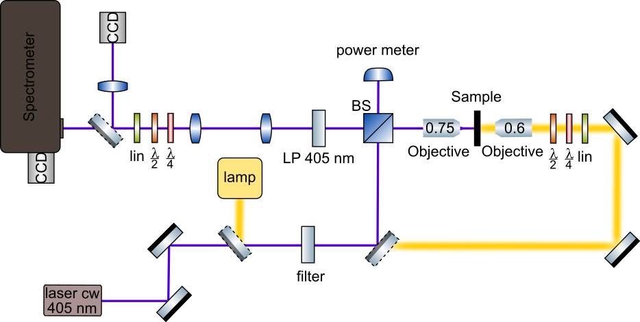
Optical measurements. Figure 6 shows the scheme of the experimental setup used for the optical measurements in both configuration: reflectance and transmission. The measurements were performed at room temperature using a continuous wave laser at 405 nm for photoluminescence (PL) excitation and a white light lamp for the reflectance and transmission spectra. PL measurements were realized in the reflection configuration.
Absorbance measurements. Absorption measurements of the PEPI perovskite on the glass substrate were performed using a CARY 5000 UV-Vis-NIR spectrometer. The absorption spectrum is presented in Fig. 2a.
Ellipsometry measurements. The refractive index of polycrystalline PEPI perovskite (presented in Fig. 2d) was estimated based on ellipsometric data from RC2 ellipsometer (J.A. Woollam Co) in 450-1690 nm spectral range. To increase the sensitivity of the measurement and retrieve anisotropy more accurately two different types of samples were prepared. In the first set of samples, PEPI was spin-coated on the silicon wafer with a 618 nm thick layer of thermal oxide to utilize the interference enhancement effect. Then all 16 Mueller matrix (MM) elements in reflection were acquired for angles of incidence from 55∘ to 70∘ by 5∘. In the second case, the PEPI layer was spin-coated on a 1 mm thick transparent fused silica substrate. For this set of samples, transmission ellipsometry and transmission intensity data for illumination angles ranging from 0∘ to 40∘ by 5∘ were acquired additionally. Such a combination helps to reduce the correlation between the model parameters, leading to a unique solution. Almost negligible values of off-diagonal terms and off-diagonal blocks in the MM data collected in the reflection mode reveal no cross-polarization between - and - states and indicate that the sample under investigation is either isotropic or uniaxial with a -plane anisotropy. As the sample rotation does not influence the MM elements, we assume that the c-axis is perpendicular to the sample surface. All further data analysis was performed using the CompleteEASE software. The datasets were combined in a multisample model with the same optical constants for each PEPI layer. We use the general oscillator approach to retrieve the dielectric permittivity function, constrained with Kramers-Kronig consistency. Typically the presence of anisotropy alters the shape of features in the ellipsometric data. In the studied case of PEPI layers, incorporation of anisotropy into the model leads to 75% improvement of the Mean Square Error (MSE) of the dielectric permittivity function fit, which confirms that the spin-coated material exhibits anisotropy.
Coupled oscillators model. Coupled oscillator model presented by solid lines in Fig. 2b,c was fitted to the experimental data independently for measurements in horizontal and vertical polarization.
For the horizontal polarization (Fig. 2b) of the polariton modes, the Hamiltonian solution is:
| (6) |
Fitting with exciton energy eV resulted in coupling strengths of: meV, meV, meV.
For the vertical polarization (Fig. 2c) of the polariton modes, the Hamiltonian solution is:
| (7) |
Fitting with the same exciton energy leads to coupling strengths of: meV, meV.
Dispersion relations of uncoupled photonic modes are marked in Fig. 2b,c with white dashed lines.
Berreman Method. The spectra presented in Fig. 2e,f show the reflectance calculated for H and V incident light polarization using Berreman method [62].
Simulated cavity consists of 2 DBR mirrors made of 5 pairs of \chSiO2 and \chTiO2 layers calculated for maximal reflectance at 530 nm. Space between the mirrors consists of LC part and 120 nm thick perovskite layer directly on top \chSiO2 layer of DBR. To match position of the cavity modes with experiment, the LC layer is separated into three parts: two interface layers described by an isotropic ordinary refractive index with thickness of 170 nm and central anisotropic LC layer with thickness of 845 nm described by diagonal dielectric tensor with extraordinary refractive index along direction and for two remaining directions.
and values of the LC are based on Ref. [47] and refractive indexes of the perovskite layer are presented in Fig. 2d.
In the simulations shown in Fig. 4c,e,k,l,m the total length of the LC cavity is equal to nm. Twisted nematic orientation of the LC molecules around axis occurs within distances nm at the DBR/LC interface with total 45 deg reorientation between the top and bottom DBR. Simulations shown in Fig. 4 were performed with an additional rotation of LC by 42.5 deg around axis. Simulations were performed with 5 \chSiO2/\chTiO2 DBR pairs centered at 555 nm.
The dispersion of the cavity modes obtained from the Berreman method was fitted with Eq. (5) with parameters: eV, meV, meV, , , meVm2, meVm2, meVm2, eVm.
Calculations presented in Fig. 5a–f were performed for the same parameters but with meV observed on the sample with 30 deg rubbing disorientation (see Supplementary Materials).
To calculate the Berry curvature we follow the procedure described in Ref. [41]. Based on the Stokes parameters, we define angles:
| (8) |
| (9) |
and calculate Berry curvature as
| (10) |
Acknowledgments
This work was supported by the National Science Centre grants 2019/35/B/ST3/04147, 2019/33/B/ST5/02658, 2018/31/N/ST3/03046 and 2017/27/B/ST3/00271. We acknowledge the European Union’s Horizon 2020 program through a FET Open research and innovation action under the grant agreement No. 899141 (PoLLoC) and No. 964770 (TopoLight). We also acknowledge the NAWA Canaletto grant PPN/BIT/2021/1/00124/U/00001. H.S. acknowledges the Icelandic Research Fund (Rannis), grant No. 217631-051.