Adaptive relaying for streaming erasure codes in a three node relay network
Abstract
This paper investigates adaptive streaming codes over a three-node relayed network. In this setting, a source node transmits a sequence of message packets to a destination through a relay. The source-to-relay and relay-to-destination links are unreliable and introduce at most and packet erasures, respectively. The destination node must recover each message packet within a strict delay constraint . The paper presents achievable streaming codes for all feasible parameters that exploit the fact that the relay naturally observes the erasure pattern occurring in the link from source to relay, thus it can adapt its relaying strategy based on these observations. In a recent work, Fong et al. provide streaming codes featuring channel-state-independent relaying strategies. The codes proposed in this paper achieve rates higher than the ones proposed by Fong et al. whenever , and achieve the same rate when . The paper also presents an upper bound on the achievable rate that takes into account erasures in both links in order to bound the rate in the second link. The upper bound is shown to be tighter than a trivial bound that considers only the erasures in the second link.
Index Terms:
Cloud Computing, Streaming, Low-Latency, Symbol-Wise Decode-and-Forward, Adaptive Relay, Forward Error Correction, Packet Erasure Channel, Relayed NetworkI Introduction
A number of emerging applications including online real-time gaming, real-time video streaming (video conference with multiple users), healthcare (under the name tactile internet), and general augmented reality require efficient low-latency communication. In these applications, data packets are generated at the source in a sequential fashion and must be transmitted to the destination under strict latency constraints. When packets are lost over the network, significant amount of error propagation can occur and suitable methods for error correction are necessary.
There are two main approaches for error correction due to packet losses in communication networks: Automatic repeat request (ARQ) and Forward error correction (FEC). ARQ is not suitable when considering low latency constraints over long distances, as the round-trip time may be larger than the required delay constraint. For that reason, FEC schemes are considered more appropriate candidates. The literature has studied codes with strict decoding-delay constraints—called streaming codes—in order to establish fundamental limits of reliable low-latency communication under a variety of packet-loss models. Previous works have studied particular, useful cases. In [2], the authors studied a point-to-point (i.e., two nodes—source and destination) network under a maximal burst erasure pattern. In [3], the authors have studied, separately, burst erasures and arbitrary erasures. In [4], the authors have extended the erasure pattern, allowing for both burst erasures and arbitrary erasures. In particular, it was shown that random linear codes [5] are optimal if we are concerned only with correcting arbitrary erasures. Other works that have further studied various aspects of low-latency streaming codes include [6, 7, 8, 9, 10, 11, 12, 13, 14].
While most of the prior work on streaming codes has focused on a point-to-point communication link, a network topology that is of practical interest involves a relay node between source and destination, that is, a three-node network. This topology is motivated by numerous applications in which a gateway server, able to decode and encode data, connects two end nodes. Motivated by such considerations, streaming codes for such a setting were first introduced in [15], which derived the time-invariant capacity for the three-node setting, and further extended to a multi-hop network in [16].
However, the work in [15] is constrained to time-invariant codes, in particular, the relay does not exploit the knowledge about the erasure pattern it has observed in order to improve its coding scheme. On the other hand, the work in [16] allows for channel adaptation, however, applying the scheme presented in that work in the reduced three-node relayed network does not improve the rate of the streaming code above [15], and gains are only observed in the multi-hop setting.
In our work, we present an achievable coding scheme that is able to outperform the rate achieved by [15, 16] in the three-node relayed network. Furthermore, we present a novel optimization-based upper bound for this setting and an heuristic to find a solution for that optimization.
I-A Related Works and Applications
Our work follows the same adversarial packet erasure channel model used in previous works such as [2, 3, 4, 13, 14]. In these works, there is a limit on the number of erasures that may occur, and the goal is to achieve error-free communication within the strict delay constraint. Adaptation of the encoding strategies has been studied in [17, 18] in order to adapt to changing channel statistics. In these works, such adaptation is performed using random linear codes. Relay adaptation has been studied in [16] in order to transmit over a multi-hop setting.
The setting we study, with an intermediate relay between a source and destination, can be used to model communication between a user and a server. In such scenario, it is common that the user communicates with a nearby node that is connected to the same network as the server, and this node then communicates with the server through an internal network. In this case, the link from source to relay models the path from the user to this intermediate node, and the link from relay to destination models the path from it to the server, or vice-versa. In many applications where such a network setting is common, low latency is desirable—frequently, reducing latency is the reason the internal network is built, so the routing can be optimized to reduce delay (e.g. Riot Games’ network [19] or WTFast network [20]), rather than the number of hops, which is usually desired by regular Internet Service Providers.
Furthermore, the impact of latency on the user experience in applications such as cloud gaming, where a cloud server performs the computationally intensive tasks such as video rendering, and then transmits only the video output to the player, has been widely studied [21, 22, 23, 24, 25, 26, 27]. This latency has different sources, such as propagation delay, hardware delay, server-side processing delay and communications delay, and reducing many of them has been studied, such as server-side delay [28], video-encoding optimization [29] and, as mentioned previously, reducing propagation delay by building internal networks optimized to reduce latency. However, reducing the communication delay seems to be understudied, in particular, the delay caused by packet losses. Considering that the round-trip-delay often represents more than 20% of the delay budget in these applications [30], re-transmissions represent a significant cost in the delay budget. Using streaming codes could make these re-transmissions unnecessary, freeing up a significant fraction of the delay budget.
Similar scenarios appear naturally in other settings, such as virtual and augmented reality, where latency has been linked to motion sickness [31], and, again, e.g. in VR cloud computing, the user communicates with an intermediate node which then communicates with the server.
II System Model and Main Results

In this section, we formally introduce the problem setting. We use the following notation throughout the paper. The set of non-negative integers is denoted by . The finite field with elements is denoted by . The set of -dimensional column vectors over is denoted by . For , we use to denote . Naturally, we set .
Consider a three node setup consisting of a source, relay and destination. All packet communication happening in source-to-relay and relay-to-destination links are assumed to be instantaneous, i.e., with no propagation delays. In each discrete time slot , the source has a message packet available, which needs to be communicated to the destination via relay. For simplicity, we assume that , if . Towards this, at time-, source invokes a source-side encoder to produce a source packet , which is obtained as a function of message packets . Source transmits to the relay over a packet erasure channel. Let denote the packet received by relay. We have:
| (3) |
In time-, once relay receives , it produces a relay packet by invoking a relay-side encoder:
| (4) |
The relay packet is a function of packets . Relay transmits to the destination in time-. Owing to erasures in relay-to-destination link, the packet received by destination in time- is given by:
| (7) |
At time-, destination uses decoder:
| (8) |
to obtain an estimate of as a function of received packets . The decoder is delay-constrained as has to be estimated by time-. The tuple constitutes an streaming code. This setting is illustrated in Fig. 1.
Definition 1 (Rate of a streaming code).
The rate of an streaming code is defined to be .
Definition 2 (Erasure Sequences).
A source-relay erasure sequence denoted by is a binary sequence, where iff . Similarly, a relay-destination erasure sequence will have iff
Definition 3 (-Erasure Sequences).
Let . A source-relay erasure sequence is defined to be an -erasure sequence if . Similarly, is an -erasure sequence if .
Definition 4 (-Achievability).
An streaming code is defined to be -achievable if it is possible to perfectly reconstruct all message packets (i.e., for all ) at the destination in presence of (i) any -erasure sequence and (ii) any -erasure sequence . Similarly, a rate is said to be -achievable if there exists an code such that: the code is -achievable and .
Definition 5 (-Capacity).
The -capacity, denoted as , is the maximum of all rates that are -achievable, as defined in Definition 4.
It may be noted that, if , the -capacity is 0.
Remark 1.
Error protection provided by -achievable streaming codes may appear to be limiting, as they consider only erasures across all time slots in source-relay link and erasures across all time slots in relay-destination link. However, owing to the delay-constrained decoder, these codes can in fact recover from any , which satisfy: and for all . i.e., in any sliding window of consecutive time slots, source-relay and relay-destination links see at most and erasures, respectively.
III Proposed Scheme
In this section, we present the code construction and the achievable rate of such streaming code. We start by stating our main results, then, we present the main ideas that lead to these results, a toy-case example demonstrating the key ideas, and finally the general code construction.
Theorem 1.
For any , and , there exists an -achievable streaming code with rate where
| (9) | ||||
| (10) |
and where is an overhead bounded by , where is an arbitrary integer constant, thus the overhead goes to 0 as increases.
Remark 2.
In Theorem 1, the term represents the fact that, since the relay is changing its coding strategy according to the erasure pattern that has occurred in the link from source to relay, that erasure pattern must also be informed to the destination by the relay. In order to keep it simpler, we present our examples and highlight the main ideas assuming the destination is given the erasure pattern that has occurred from source to relay. We also present a naive solution to transmit this necessary information, which is independent of the packet size, thus, by making the code infinitely large, this overhead is negligible. In the theorem, the constant represents the number of codewords we multiplex in the same packet, thus increasing it increases the packet size and makes the overhead negligible. More details are given in the end of Section III-E.
Corollary 1.
For any and , for a sufficiently large , there exists an -achievable channel-state-dependent streaming code that achieves a rate (strictly) higher than which is the rate achieved by channel-state-independent -achievable streaming codes [15].
III-A Main Ideas
As mentioned in previous sections, our streaming code differs from the one presented in [15] mainly in its relaying function. The encoding function from source to relay follows the same core idea. However, the relaying function differs greatly by employing the knowledge of the erasure pattern that has occurred. Below, we highlight the main concepts which allow us to exploit that knowledge.
III-A1 Packet-wise variable rate
In our coding scheme, from relay to destination, each message packet is transmitted using a different rate, based on the erasure pattern its respective source packet has been subject to in the link from source to relay. In [15], each message is transmitted assuming it has been subject to the worst case erasure pattern, which leads to every message being transmitted with an effective delay of from relay to destination. In other words, in prior works, information about a message packet is only relayed starting at time , even though it might have been recovered earlier than that, which occurs, for example, if the respective source packet has not been erased. This implies that the respective message packet can be transmitted with effective delay equal to , that is, the source-to-relay link has introduced no delay to that message packet. Furthermore, from our channel model assumptions, some source packets are guaranteed to not be erased (otherwise the capacity is 0), thus, some message packets can certainly be transmitted from relay to destination with effective delay . Since these packets can be transmitted with a higher effective delay, they can be transmitted with a higher rate, which will lead to a higher overall rate, as we will see later. This also leads to a variable streaming code rate, however, we handle that by zero padding.
III-A2 Within-message variable rate
Not only each message packet is transmitted with a different rate according to the erasure pattern it is subject to in the first link, this rate is also adapted on the fly as new erasures occur. For example, consider source packet has been erased. At time , message packet is subject to one erasure. Then, assume we successfully recover . The relay start transmitting some information about . Up to this point, only one erasure has occurred, and we transmit accordingly. Then, assume is again erased. Now, is subject to two erasures, rather than one, and its rate of transmission should adapt accordingly to a lower rate. We achieve this rate adaptation by using long maximum-distance separable (MDS) codes, which encode across all message symbols and allow for variable-rate transmission, rather than diagonally-interleaved “short” MDS codes, which were used in prior works.
III-A3 Noisy Relaying
Another key difference is that, in [15], the concept of “symbol-wise decode-and-forward” was introduced, where the relay decodes symbols of the message packet and then forwards them. However, the relay is only able to forward information about symbols it has been able to fully recover. In our coding scheme, the relay transmits noisy symbols, i.e., symbols that contain interference caused by past message packets. Because the destination is required to recover packets sequentially, interference of past messages can be cancelled by the deadline at the destination.
III-B Example
Consider, for example, a network with , and . Let us consider , that is, each message packet consists of 24 symbols. We denote by the th message symbol at time . We use the notation and .
As we show next, the source is using the same coding scheme as [15] which amounts to a systematic transmission with diagonally interleaved block codes which results in transmitting at rate of .
First, let us consider the scenario where the erasures in the first link occur in a burst. As can be seen in Table I, the relay starts transmitting source packets that have not been erased immediately with rate . This can be seen, for example, for . On the other hand, source packets that are subject to erasures are transmitted with lower rate, since they need to be transmitted “faster” (i.e., with a smaller effective delay). Thus, it can be seen that is transmitted with rate and is transmitted with rate . This highlights the packet-wise variable rate aspect of our coding strategy. Further, note that the relay is unable to recover the symbols at time 6. If the relay would wait until it can be recovered without the interference from , then would also need to be transmitted with rate . In order to be able to transmit it with a better rate, we instead transmit the noisy symbols . Then, at the destination, since it can recover entirely at time 10, it can cancel out the interference at time 11 and recover . This highlights the concept of noisy relaying.
| Time | 3 | \cellcolor[HTML]FFCCC9 4 | \cellcolor[HTML]FFCCC95 | 6 | 7 | 8 | 9 | 10 | 11 |
| \cellcolor[HTML]FFCCC9 | \cellcolor[HTML]FFCCC9 | ||||||||
| Source | \cellcolor[HTML]FFCCC9 | \cellcolor[HTML]FFCCC9 | |||||||
| \cellcolor[HTML]FFCCC9 | \cellcolor[HTML]FFCCC9 | ||||||||
| \cellcolor[HTML]FFCCC9 | \cellcolor[HTML]FFCCC9 |
| Time | 3 | 4 | 5 | 6 | 7 | 8 | 9 | 10 | 11 |
| Relay | |||||||||
| \cellcolor[HTML]FFFFC7 |
Let us now consider the scenario where the erasures are spaced, as shown in Table II. Since is subject to only one erasure, we attempt to transmit it with rate , similar to how the packet was transmitted in the previous example. However, another erasure occurs at time 6 and therefore the relay does not have enough symbols to keep transmitting with such high rate. Instead, we simply transmit the remaining symbols that have been previously recovered at time 5. Then, at time 7, we start transmitting with rate , and we change the rate used for from to , as it now has been subject to two erasures. This highlights the concept of within-message variable rate.
| Time | 3 | \cellcolor[HTML]FFCCC9 4 | 5 | \cellcolor[HTML]FFCCC96 | 7 | 8 | 9 | 10 | 11 |
| \cellcolor[HTML]FFCCC9 | \cellcolor[HTML]FFCCC9 | ||||||||
| Source | \cellcolor[HTML]FFCCC9 | \cellcolor[HTML]FFCCC9 | |||||||
| \cellcolor[HTML]FFCCC9 | \cellcolor[HTML]FFCCC9 | ||||||||
| \cellcolor[HTML]FFCCC9 | \cellcolor[HTML]FFCCC9 |
| Time | 3 | 4 | 5 | 6 | 7 | 8 | 9 | 10 | 11 | 12 |
| Relay | ||||||||||
In general, our scheme attempts to transmit each source packet with the maximal possible rate, i.e., , where is the number of erasures observed so far that affect packet . As soon as it observes a new erasure, (by updating this ) it reduces the rate of transmission of the affected message packets. Further, it also transmits noisy symbols when required, knowing that the noise can always be cancelled at the destination due to the sequential nature of delay-constrained streaming communications. In the following section we present the general code construction.
III-C Code Parameters
For given parameters , we set message packet, source packet sizes as the following:
| (11) | ||||
| (12) | ||||
| (13) |
Remark 3.
This choice is to ensure that every subcode from relay to destination (which have a rate of the form as mentioned previously) can be met with integer parameters.
We represent the message packet as a column vector of the form:
| (14) |
We now proceed to explain the encoding strategy in each link, and show that this encoding strategy results in an achievable rate which is equal to the one stated in Theorem 1.
III-D Source-to-Relay Encoding
As mentioned previously, the source-to-relay encoding is similar to the previous work on [15]. The major difference is that we use multiple “layers” of the same code. This can be seen in the previous example, where we use 12 layers of a code, that is, we replicate a diagonally-interleaved MDS code twelve times.
In general, we use layers of diagonally-interleaved -MDS codes with parameters and . The construction of the diagonally-interleaved MDS code can be found in, e.g., [15]. Our code can be constructed by simply “appending” the codewords from each layer together. Then, we can write . The encoding scheme is illustrated in Fig. 2.
Now, we make a major observation about such codes. Using Lemma 3 from [15], we know that, if has been erased, then symbols of can be recovered at time , another symbols can be recovered at time , and so on, until the entire message has been recovered. This observation is guaranteed independent of erasure pattern, as long as at most erasures occur. However, considering the erasure pattern, we make a stronger claim about the recovery of symbols and, especially, “noisy symbols”, which we now define simply as estimates.
Definition 6.
We say is an estimate of a source symbol if there exists a function such that .
That is, is an estimate of if, given past () message packets, we are able to recover .
Proposition 1.
Assume the packet is erased. Then, new estimates of symbols of can be recovered from each subsequent non-erased packet , , until estimates of all symbols have been recovered.
To clarify the statement of our proposition, “new” estimates mean that the estimates the relay is able to decode from each non-erased packet are always estimates of symbols for which the relay did not have an estimate yet.
To understand this definition and proposition, let us consider the examples given previously. First, consider the example in Table II. In this example, it is straight forward that the relay can recover 12 symbols from at time 5 (from the first non-erased packet after time 4) and another 12 symbols at time 7 (from the second non-erased packet). However, in the example in Table I, the relay only has access to the so-called estimates of 12 symbols of at time 6, since there is still interference from . Nonetheless, as can be seen in the example, relaying these estimates is enough, since the destination will have access to previous messages by the deadline of recovery.
III-E Relay-to-Destination Encoding
The relay employs two different encoding mechanisms depending on whether the source packet sent from source is successfully received (non-erased) or not (erased). In each time-, relay transmits a relay packet which is a function of all non-erased source-to-relay source packets within the set . For ease of exposition, we will view each as an unordered set of symbols, rather than a column vector.
III-E1 is Non-Erased
In this case, since we use systematic encoding from source to relay, the entire message packet is immediately available to the relay at time . The relay will then partition the message packet into message sub-packets, denoted as . That is, is the th sub-packet of the message packet . From (11) and , it follows that each sub-packet is of size . The relay will then employ diagonal interleaving using -MDS codes for each sub-packet, as follows.
Let denote the generator matrix of the -MDS code and let each message sub-packet to be represented as a column vector as follows
and so on. Let
Then, for all , the relay appends to , respectively.
That is, each sub-packet is encoded into a diagonal that goes from up to , where the packets at times contain systematic symbols, and the remaining packets at times contain parity symbols. Note that there are exactly parity symbols for each sub-packet.
Thus, each non-erased source packet contributes symbols to each of the relay packets . Note that this is not a systematic streaming code, as the message packet is not fully included in the packet . That is, in the relay-to-destination code, all symbols from each sub-packet belong to the same underlying MDS code, unlike in the source-to-relay code.
It should be easy to see that we are able to recover from any erasures using this coding scheme. The rate used is also intuitive: since no erasures occurred from source to relay, we transmit with the same rate as a point-to-point streaming code with delay constraint and arbitrary erasures.
III-E2 is Erased
On the other hand, if is erased, then the relay has no information of at time , and the relay will follow a different encoding strategy. Let be a set of code symbols (to be viewed as a column vector) computed by the relay as a function of all non-erased source packets in time slots . The size of each can vary from 0 up to . Our coding strategy consists of including as a part of , . In the following, we discuss (i) how to determine , (ii) how we obtain a relay packet size which matches (13) and (iii) how we can guarantee that is recoverable at the destination at time under any erasures in the relay-to-destination link.
Let denote the set containing the first time slots in during which there are no erasures in the source-to-relay link. From Proposition 1, we know that, at time , the relay has access to estimates of symbols of , for all .
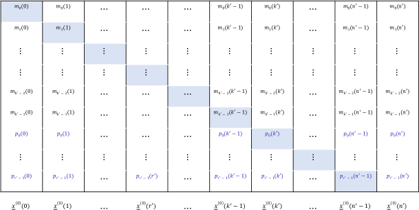
We start by describing an overview of our coding scheme, without specifying the sizes of each . Consider a “long” systematic -MDS code, , that is, an MDS code which encodes all symbols from the message packet into coded symbols. The parameter , as we will explain now, depends on the erasure pattern in the source-relay link. Let us start by constructing a length- row-vector which is a codeword of this long MDS code.
In order to construct , the initial code symbols of are estimates of the symbols of . More specifically, the first code symbols of are the estimates of determined by relay at time (i.e., from the first non-erased source packet), the next code symbols are the estimates determined at time (second non-erased source packet) and so on, up to the first symbols of . On the other hand, the final code symbols of are MDS parity symbols obtained as a function of the initial code symbols of .
Now, let us discuss how to obtain from . Let us define as the size of , and let our codeword be written as . Then, from definition, we should have . We now discuss how to determine .
Consider time slots . From assumption, is erased and there can be at most more erasures in time slots (in the source-to-relay link). Let us denote by the cumulative number of estimations of message symbols of available to the relay at time . Then, is obtained as described in Algorithm 1. Note that for the reminder of this section, has a special meaning as described in Algorithm 1, and should not be confused with the generic running index used in notation previously.
To illustrate, let us analyze the code used for the transmission of packet in the example. In Table I, we start with , that is, we shall analyze how many symbols should be transmitted at time 5, i.e., . Following our algorithm, is erased. So far, we have not recovered any symbols from , therefore, , and we have . This can be seen from the fact that we do not transmit any symbols from at time 5 in the example. Afterwards, for , we are able to recover symbols, so we have . Following the algorithm, since is not erased, we have . The same goes for the remaining of the transmission.
On the other hand, in Table II, we have , and we have , since we recovered 12 symbols. Then, at time 6, is erased, thus, we transmit the minimum between and , i.e., 4 symbols. Finally, we have for all other packets, since now , as before.
This is just a greedy algorithm such that as many symbols are included in subject to following constraints:
-
1.
,
-
2.
is a function of message symbol estimates of obtained by relay in non-erased time slots among ,
-
3.
is a codeword of a systematic -MDS code. Initial code symbols message symbol estimates of .
Note that, because of item 1, we are guaranteed to always have enough symbols to transmit because, if is not erased, then we recover at least as many symbols as we transmit, and if is erased, then we transmit the minimum between how many symbols we have available and , which is from definition at most the number of symbols we have available.
III-E3 Worst-Case Length of Relay Packets
We now wish to show that, using our code construction, the maximum packet length is at most the one described in (13). For consistency, all packets which would have a smaller packet length than the maximum are zero-padded in order to keep a constant packet length as defined in the problem statement.
First, let us note that, if is not erased, it appends exactly symbols to each relay packet in time slots from up to , where recall that . Thus, at some arbitrary time , each non-erased source packet , contributes symbols to .
Now, let us assume that there are erasures at time slots , where . Now, note that from time up to time , erasures have occurred, from definition. Recall also that in Algorithm 1. Finally, note that . From these properties, we have that
where is the number of symbols appended to due to the erasure in the link from source to relay at time .
Therefore, the packet length of is at most
| (15) | ||||
| (16) |
Now, note that , thus, maximizes this packet length and is therefore the worst case. We then have that , which matches (13).
Finally, we should note that, since the relay changes its coding strategy according to the erasure pattern observed in the first link, this erasure pattern must also be relayed to the destination, so it knows how to decode. A naive solution is to, at time , transmit the erasure pattern observed from time up to , which is a binary sequence of length , and does not depend on the packet size. Thus, by making the packet size go to infinity, the rate approaches
III-E4 Recoverability of at Destination by Time-
We have shown that our code construction achieves the desired rate, however, it remains to show that our code is -achievable, and therefore so is the proposed rate.
Note that Proposition 1 shows that the relay is able to recover the estimates of . Now, it suffices to show that, with the proposed code construction, the destination has access to enough estimates to recover entirely.
Proposition 2.
Using our coding scheme, if there are at most erasures from relay to destination, the destination is able to recover an estimate of at time .
Proof:
Note that, from relay to destination, all message packets are transmitted within the same MDS code. We split the analysis in two cases, depending on whether has been erased or not. If has not been erased, then each message sub-packet is encoded using a -MDS code, and at most erasures may occur, therefore, it is straight forward that all symbols can be recovered, since each layer recovers its own symbols and there are layers.
On the other hand, if has been erased, we again split the analysis in two cases. In the first case, let us assume for every , that is, we always have enough symbols to transmit the maximum we wish to. In this case, for all . Since there are at most erasures, there are at least available packets, thus we can recover all message symbols.
Finally, the last case occurs when has been erased, but for some . In this case, let us denote by the largest such that this condition holds. Let us state some easily verifiable facts about :
-
1.
has been erased, as otherwise we would have .
-
2.
There are erasures in the source-to-relay link in time slots .
-
3.
, as otherwise we would have .
-
4.
.
Then, for , we have
| (17) |
This follows from the fact that, for , we have from the definition of and from definition of and .
Also, for , we have
| (18) |
This again follows from the fact that, for , (recall that only counts erasures up to time ).
Also, note the following: is exactly the number of non-erased source packets from time up to , since represents the number of transmitted packets and the number of erased packets. Furthermore, we have
where follows from definition (11); follows from item 3 above; and follows from the fact that there are non-erased packets and the relay recovers estimates from each non-erased packet as seen in Proposition 1. This implies
| (19) |
where the first inequality is simply from rewriting the previous inequality and the second comes from the fact that , since at most erasures may occur from time up to (recall that has been erased).
For simplicity, let us define as the indices such that has not been erased in the link from relay to destination. Then, it follows that
| (20) | ||||
| (21) | ||||
| (22) | ||||
| (23) |
where follows from the fact that, in the worst case, from conditions (17) and (18), all are part of (otherwise we get more symbols, that is, if and , then ), and that the remaining can all be bounded by (17); follows from the fact that , from item 4 above and the fact that, for each non-erased source packet, the relay recovers estimates; and comes from the fact that, again, . The last step results from trivial arithmetic.
Then, owing to the use of the long -MDS code, since at least code symbols are available, then all estimates of message symbols of can be recovered by the delay constraint at time .
Finally, note that messages , are available from definition to the destination. Therefore, at time , since the destination is able to recover an estimate of , it is also able to recover the message packet itself. Then, at time , since it already has access to , the estimate of is enough to recover the message packet as well, and so on. Thus, from this induction argument, it is easy to see that the estimates are enough for the destination to recover the message packets by the deadline. ∎
Finally, we propose a naive way to inform the destination about the erasure pattern that has been observed: at every time instant , the relay forwards the observed erasure pattern from time up to time . This is a binary sequence of length , thus it can be represented by symbols. Further, it does not depend on the packet size, thus, we can make this overhead negligible by increasing the packet sizes. This can be easily achieved by multiplexing together copies of our code111For example, for and , this overhead is a one-byte header, which is negligible in a 256 bytes packet..
Finally, since we have presented an -achievable code with rate as described in Theorem 1, the proof of the theorem is complete.
IV Upper Bound
| Time | ||||||||
| Source-Relay | \cellcolor[HTML]FE0000 | \cellcolor[HTML]FE0000 | ||||||
| Relay-Destination | \cellcolor[HTML]FE0000 | \cellcolor[HTML]FE0000 | \cellcolor[HTML]FE0000 | \cellcolor[HTML]FE0000 |
We start the upper bound presentation by showing a toy-case example for which we show that an -achievable code must be able to recover from more than erasures in the second link under some particular conditions. Let us consider the erasure pattern in Table III. Note that, from time to , there are erasures. However, consider the following argument: at time , all source packets from time up to must have been recovered. Furthermore, since has been erased, and due to causality, packet must be a function only of packets from time up to , as the relay has not yet received any information about packet . Therefore, at time , that is, at the deadline for recovery of packet , the destination must be able to generate , thus its erasure should not affect the recovery of . This example is formalized in the following entropy equations
where follows from the fact that, at time , all packets from time 0 up to must be recoverable, since, up to this point, at most erasures have occurred in the second link, and at most in the first link; follows from the fact that, since has been erased, must be a function only of message packets up to time , due to causality; and follows from the fact that only and are missing, thus it is as if only erasures have occurred, and therefore must be recoverable. Then, by repeating this erasure pattern with a period of , and simply computing the ratio of non-erased packets to total packets in the second link, we get that . On the other hand, the trivial bound in this scenario would be . If we consider only time-invariant codes, then the upper bound is given by , which is clearly lower than ours. However, it applies only to time-invariant codes, and in fact we can achieve higher than that using our adaptive coding scheme presented in the previous section, which, in this example, achieves , ignoring the overhead.
The following lemma generalizes this key concept and allow us to make an induction argument in the sequence.
Lemma 1.
Assume that, at time , the destination has access to message packets {. Then, if the following conditions hold, an -achievable code must be able to recover .
| (24) | ||||
| (25) | ||||
| (26) |
Proof:
Let us split the proof in two cases. First, if , the proof follows immediately
| (27) | ||||
| (28) |
since, from assumption, the code is -achievable, therefore, it must be able to recover from any erasures in the first link and erasures in the second link. In particular, since the destination has access to all previous message packets, it is able to generate all channel packets from time up to , independent of the erasures that have occurred in the past. Therefore, it is “as if” only the erasures from time up to have occurred.
Now, let us consider the more interesting case, which is when . In this case, we have
| (29) | ||||
| (30) |
where, again, since the destination has access to previous message packets, it is able to generate all the channel packets from source to relay . However, since , we have that must also be a function of , thus the destination can also generate the channel packet . Then, again, it is “as if” only the erasures from time up to have occurred from relay to destination, and, since there are at most erasures in this window, packet must be recoverable. ∎
We now apply this Lemma in an induction argument in order to state that not only we must be able to recover from a sliding window, as shown in e.g. [2] and recalled in Remark 1, we must be able to recover from a sliding window that, sometimes, allows for more than erasures in the second link.
Lemma 2.
If a code is -achievable, then it must be able to correct any erasure patterns for which the following holds:
| (31) | ||||
| (32) | ||||
| (33) |
Remark 4.
These conditions lead to a tighter upper bound than the trivial bound that only considers the second link, which is represented by the condition . In particular, (33) allows for more erasures in a window than the trivial bound allows, thus, there are less available non-erased packets and the rate must be lower. In other words, the erasure sequence used in the trivial bound meets the conditions of Lemma 2, and allowing for more possible erasure sequences can only improve the upper bound.
Proof:
This follows directly from an induction argument using Lemma 1. Note that, from definition, at time , the destination has access to message packets , . Therefore, if conditions (24)-(26) hold for , packet is recoverable. Then, at time , the destination has access to , and if the conditions hold for , it can also recover , and so on.
Formally, assume that, at time , the destination has access to all message packets , . Then, under the assumptions of this Lemma and applying Lemma 1, at time , the destination will have access to all message packets , . That is, if, at any time instant, all previous message packets are known to the destination, then, under our assumptions and using Lemma 1, all following message packets will also be recoverable by the destination. Finally, remember that, by assumption from the model, , is known to the destination. Therefore, under the assumptions of this Lemma, all message packets are recoverable by the destination. ∎
This Lemma provides us a framework to try and find an optimal erasure pattern pair which fulfills the desired constraints.
Proposition 3.
An upper bound to the rate in the second link can be found by solving the following optimization problem
| s.t. | ||||
| (34) |
where the optimization is over the valid erasure sequences that satisfy Lemma 2.
Proof:
We have shown, in Lemma 2, that if a code is -achievable, it must be able to recover from an erasure sequence that meets the conditions in Lemma 2. Given a valid erasure sequence, it is easy to see that the rate must be below the ratio of non-erased packets (using the given erasure sequence) to total packets. This holds for any window of length , and it gets tighter as , as the difference between (total source packets) and (total encoded packets) becomes negligible.
That is, the optimization is simply finding the valid erasure sequence that meets the conditions given by Lemma 2. ∎
In our example, an erasure sequence that satisfies Lemma 2 can be found by repeating the pattern in Table III with period 7. This can be seen by the fact that, when an erasure occurs in the first link (e.g. at time ), the constraint is that the number of erasures from time up to is less than or equal to , which holds. In other windows, where there are no erasures in the first link, the constraint is that the number of erasures is at most , which again holds. Then, an upper bound is simply given by the ratio between non-erased packets (4) to total packets (7) for this specific erasure pattern. However, we do not claim that the erasure pattern presented in Table III is optimal, instead, it is one valid erasure sequence which results into one valid bound.
However, solving this optimization problem is not trivial. Instead, we propose a heuristic algorithm for the adversary, which attempts to maximize the number of erasures it introduces in the relay-destination channel. The algorithm is described in Algorithm 2.
The idea for the algorithm is simple: we introduce erasures in the second link in a greedily manner, always in the end of the window (i.e., at time ). This ensures that introducing this erasure will not make any previous window invalid, that is, it will not increase the number of erasures in any previous window to more than it is allowed. Furthermore, under our constrained framework, introducing erasures in the first link only improves the upper bound by allowing one extra erasure in the second link for the same time instant. For that reason, we only introduce erasures in the first link at times when there is already an erasure in the second link and that being able to introduce one extra erasure helps, that is, when the number of erasures in the window is already .
Further, we note that the source is not able to adapt to any erasure pattern, thus the cut-set-like bound from [15] for the first link holds even in the adaptive case. That is, as in [15], we can upper bound the capacity by analyzing the first link and noting that the relay must recover every message packet with delay , otherwise a burst of erasures in the second link makes that information impossible to recover. Thus, as in the prior works, we can bound . Finally, this allows us to present the following upper bound.
Theorem 2.
The -capacity is upper bounded by
V Results
To validate our construction, we consider multiple settings with the parameters drawn randomly with the following conditions:
-
•
. The condition is so that the second link is the bottleneck. Otherwise, both our coding scheme and the non-adaptive coding scheme from [15] are optimal.
-
•
. The second condition is so that the capacity is not trivial (i.e. not zero).
With the range of parameters, we hope to observe most meaningful scenarios: and can be close or fairly separated and the delay constraint can be tight or loose with respect to the number of erasures.
Then, for each randomly chosen set of parameters, we compute a trivial upper bound, which is obtained by reducing the relayed-setting to a point-to-point setting from relay to destination, the achievable rate from [15], our upper bound and our achievable rate. Then, for presentation, we sort the results according to the trivial bound, in increasing order, and present it in Fig. 3.
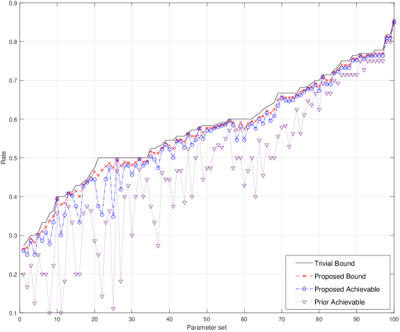
It can be seen that our achievable rate is strictly better than the non-adaptive achievable rate, with gains above 100% for some sets of parameters. We also observed that our upper bound is tighter than the trivial bound in all scenarios, although the difference might be negligible for some setting parameters.
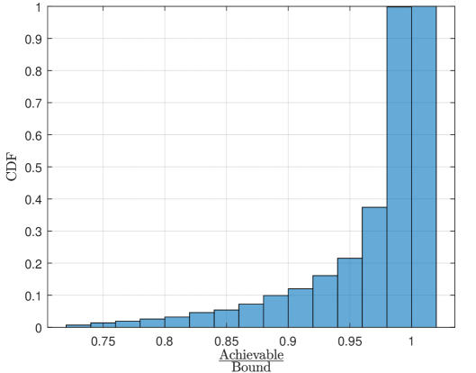
We also present the CDF of the ratio between our achievable rate and our upper bound. As can be seen in Fig. 4, our coding scheme achieves higher than 95% of the upper bound in more than 80% of the tested scenarios, and it achieves less than 80% of the upper bound in less than 3% of the scenarios.
VI Conclusion
In our paper, we presented a novel adaptive scheme for the delay-constrained relay setting, which exploits the fact that the relay can act based on the observed erasure pattern. We also present a novel upper bound technique, which bounds the rate in the second link according to the erasure pattern observed in the first link. We compare both our achievable and upper bound to the prior work on them, and show that both are at least as good as the previous results and significantly better in some scenarios. In particular, we show that our achievable rate can be higher than twice the one from prior work, and that it is close to the upper bound most of the time.
Follow-up research includes closing the gap between achievable and upper bound, and further adapting our coding scheme to time-varying channels according to a small-frequency feedback provided from destination to the relay and from the relay to source, or directly from destination to source.
Proof:
Let us first assume that is erased and prior message packets are known by the relay. We wish to show that, with every non-erased source packet , , the relay will be able to decode symbols of . This will imply that, after successfully received source packets, the relay is able to fully decode .
In order to see this, consider the sequence of source sub-packets produced by interleaving systematic -MDS codes as shown in Fig. 2. Now, note that the set of code symbols (for example, the diagonal highlighted in the figure) forms a codeword of the underlying -MDS code.
Now, recall that, since we assume prior message packets are available, the message symbols are already known. In the illustrated example in Fig. 2, this means that , and so on are known, and the only unknown symbol is .
Further, note that, since one erasure has already occurred at time , then, at most more erasures may occur in the time slots . However, there are exactly parity symbols, thus, it is guaranteed that we are able to recover at least one parity symbol from , for some . Then, it is clear that we are able to recover from the first non-erased coded sub-packet after time .
Similarly, message symbol will be recovered after source packets are successfully recovered (i.e. not erased). This is because at most symbols from the underlying -MDS codes are unknown at time , thus, as soon as symbols are recovered, can be recovered.
Now, let us remove the assumption that previous message packets are known: then, instead of perfectly recovering the message symbol , we are able to recover an estimate of it, which contains some linear combination of past message symbols, that is, we recover some . It is easy to see that this meets our definition of estimate, as the interference from past message symbols can be easily removed if we have access to them.
Finally, note that so far we have discussed one sub-packet, and we have shown that each sub-packet is able to recover one symbol from each non-erased packet. Since our code construction is obtained by simply appending sub-packets, the relay is able to decode estimates with every non-erased source packet, until (an estimate of) the message packet is completely decoded. ∎
References
- [1] M. N. Krishnan, G. K. Facenda, E. Domanovitz, A. Khisti, W. Tan, and J. Apostolopoulos, “High rate streaming codes over the three-node relay network,” in 2021 IEEE Information Theory Workshop (ITW2021), October 2021.
- [2] E. Martinian and C.-E. Sundberg, “Burst erasure correction codes with low decoding delay,” IEEE Transactions on Information theory, vol. 50, no. 10, pp. 2494–2502, 2004.
- [3] D. Leong and T. Ho, “Erasure coding for real-time streaming,” in 2012 IEEE International Symposium on Information Theory Proceedings, 2012, pp. 289–293.
- [4] A. Badr, A. Khisti, W.-T. Tan, and J. Apostolopoulos, “Streaming codes for channels with burst and isolated erasures,” in 2013 Proceedings IEEE INFOCOM. IEEE, 2013, pp. 2850–2858.
- [5] T. Ho, M. Medard, J. Shi, M. Effros, and D. R. Karger, “On randomized network coding,” in Proceedings of the Annual Allerton Conference on Communication Control and Computing, vol. 41, no. 1. Citeseer, 2003, pp. 11–20.
- [6] G. Joshi, Y. Kochman, and G. W. Wornell, “On playback delay in streaming communication,” in 2012 IEEE International Symposium on Information Theory Proceedings, 2012, pp. 2856–2860.
- [7] M. Karzand, D. J. Leith, J. Cloud, and M. Médard, “Design of FEC for low delay in 5G,” IEEE Journal on Selected Areas in Communications, vol. 35, no. 8, pp. 1783–1793, 2017.
- [8] A. Badr, P. Patil, A. Khisti, W.-T. Tan, and J. Apostolopoulos, “Layered constructions for low-delay streaming codes,” IEEE Transactions on Information Theory, vol. 63, no. 1, pp. 111–141, 2017.
- [9] A. Badr, A. Khisti, W.-t. Tan, X. Zhu, and J. Apostolopoulos, “FEC for VoIP using dual-delay streaming codes,” in IEEE INFOCOM 2017-IEEE Conference on Computer Communications. IEEE, 2017, pp. 1–9.
- [10] M. Rudow and K. V. Rashmi, “Streaming codes for variable-size arrivals,” in 2018 56th Annual Allerton Conference on Communication, Control, and Computing (Allerton), 2018, pp. 733–740.
- [11] M. N. Krishnan and P. V. Kumar, “Rate-optimal streaming codes for channels with burst and isolated erasures,” in 2018 IEEE International Symposium on Information Theory (ISIT). IEEE, 2018, pp. 1809–1813.
- [12] S. L. Fong, A. Khisti, B. Li, W. Tan, X. Zhu, and J. Apostolopoulos, “Optimal streaming codes for channels with burst and arbitrary erasures,” IEEE Transactions on Information Theory, vol. 65, no. 7, pp. 4274–4292, 2019.
- [13] E. Domanovitz, S. L. Fong, and A. Khisti, “An explicit rate-optimal streaming code for channels with burst and arbitrary erasures,” arXiv preprint arXiv:1904.06212, 2019.
- [14] M. N. Krishnan, D. Shukla, and P. V. Kumar, “Low field-size, rate-optimal streaming codes for channels with burst and random erasures,” IEEE Transactions on Information Theory, pp. 1–1, 2020.
- [15] S. L. Fong, A. Khisti, B. Li, W. Tan, X. Zhu, and J. Apostolopoulos, “Optimal streaming erasure codes over the three-node relay network,” in 2019 IEEE International Symposium on Information Theory (ISIT), July 2019, pp. 3077–3081.
- [16] E. Domanovitz, A. Khisti, W.-T. Tan, X. Zhu, and J. Apostolopoulos, “Streaming erasure codes over multi-hop relay network,” CoRR, vol. 2006.05951, 2020. [Online]. Available: https://arxiv.org/abs/2006.05951
- [17] A. Cohen, G. Thiran, V. B. Bracha, and M. Médard, “Adaptive causal network coding with feedback for multipath multi-hop communications,” CoRR, vol. abs/1910.13290, 2019. [Online]. Available: http://arxiv.org/abs/1910.13290
- [18] A. Cohen, G. Thiran, V. B. Bracha, and M. Médard, “Adaptive causal network coding with feedback for multipath multi-hop communications,” IEEE Transactions on Communications, vol. 69, no. 2, pp. 766–785, 2021.
- [19] P. Maynard-Koran, “Fixing the internet for real time applications,” Feb 2016. [Online]. Available: https://technology.riotgames.com/news/fixing-internet-real-time-applications-part-ii
- [20] G. Hains, C. Mazur, J. Ayers, J. Humphrey, Y. Khmelevsky, and T. Sutherland, “The WTFast’s gamers private network (GPN ®) performance evaluation results,” in 2020 IEEE International Systems Conference (SysCon), 2020, pp. 1–6.
- [21] M. Jarschel, D. Schlosser, S. Scheuring, and T. Hoßfeld, “Gaming in the clouds: QoE and the users’ perspective,” Mathematical and Computer Modelling, vol. 57, no. 11, pp. 2883–2894, 2013, information System Security and Performance Modeling and Simulation for Future Mobile Networks. [Online]. Available: https://www.sciencedirect.com/science/article/pii/S0895717711007771
- [22] P. Quax, A. Beznosyk, W. Vanmontfort, R. Marx, and W. Lamotte, “An evaluation of the impact of game genre on user experience in cloud gaming,” in 2013 IEEE International Games Innovation Conference (IGIC), 2013, pp. 216–221.
- [23] V. Clincy and B. Wilgor, “Subjective evaluation of latency and packet loss in a cloud-based game,” in 2013 10th International Conference on Information Technology: New Generations, 2013, pp. 473–476.
- [24] M. Claypool and D. Finkel, “The effects of latency on player performance in cloud-based games,” in 2014 13th Annual Workshop on Network and Systems Support for Games, 2014, pp. 1–6.
- [25] I. Slivar, M. Suznjevic, L. Skorin-Kapov, and M. Matijasevic, “Empirical QoE study of in-home streaming of online games,” in 2014 13th Annual Workshop on Network and Systems Support for Games, 2014, pp. 1–6.
- [26] Z.-Y. Wen and H.-F. Hsiao, “QoE-driven performance analysis of cloud gaming services,” in 2014 IEEE 16th International Workshop on Multimedia Signal Processing (MMSP), 2014, pp. 1–6.
- [27] S. Schmidt, S. Zadtootaghaj, and S. Möller, “Towards the delay sensitivity of games: There is more than genres,” in 2017 Ninth International Conference on Quality of Multimedia Experience (QoMEX), 2017, pp. 1–6.
- [28] K. Lee, D. Chu, E. Cuervo, J. Kopf, S. Grizan, A. Wolman, and J. Flinn, “Outatime: Using speculation to enable low-latency continuous interaction for cloud gaming,” Microsoft Research, Tech. Rep. MSR-TR-2014-115, August 2014. [Online]. Available: https://www.microsoft.com/en-us/research/publication/outatime-using-speculation-to-enable-low-latency-continuous-interaction-for-cloud-gaming/
- [29] I. Slivar, M. Suznjevic, and L. Skorin-Kapov, “The impact of video encoding parameters and game type on QoE for cloud gaming: A case study using the Steam platform,” in 2015 Seventh International Workshop on Quality of Multimedia Experience (QoMEX), 2015, pp. 1–6.
- [30] M. Carrascosa and B. Bellalta, “Cloud-gaming: Analysis of Google Stadia traffic,” CoRR, vol. abs/2009.09786, 2020. [Online]. Available: https://arxiv.org/abs/2009.09786
- [31] J.-P. Stauffert, F. Niebling, and M. E. Latoschik, “Latency and cybersickness: Impact, causes, and measures. a review,” Frontiers in Virtual Reality, vol. 1, p. 31, 2020. [Online]. Available: https://www.frontiersin.org/article/10.3389/frvir.2020.582204