Weighted Sum Age of Information Minimization in Wireless Networks with Aerial IRS

Wanting Lyu, Yue Xiu, Songjie Yang, Phee Lep Yeoh, , Yonghui Li, ,          Zhongpei Zhang, 
Wanting Lyu, Songjie Yang and Zhongpei Zhang are with National Key Laboratory of Science and Technology on Communications, University of Electronic Science and Technology of China, Chengdu61173, China (E-mail: lyuwanting@yeah.net; yangsongjie@std.uestc.edu.cn; zhangzp@uestc.edu.cn). Yue Xiu is with Chengdu Research & Development Centre, Huawei Technologies Co., Ltd., People’s Republic of China (E-mail: xiuyuw12345678@163.com). Phee Lep Yeoh and Yonghui Li are with the School of Electrical and Information Engineering, University of Sydney, Sydney, NSW 2006, Australia (e-mail: phee.yeoh@sydney.edu.au; yonghui.li@sydney.edu.au).
Abstract

In this letter, we analyze a terrestrial wireless communication network assisted by an aerial intelligent reflecting surface (IRS). We consider a packet scheduling problem at the ground base station (BS) aimed at improving the information freshness by selecting packets based on their AoI. To further improve the communication quality, the trajectory of the unmanned aerial vehicle (UAV) which carries the IRS is optimized with joint active and passive beamforming design. To solve the formulated non-convex problem, we propose an iterative alternating optimization problem based on a successive convex approximation (SCA) algorithm. The simulation results shows significant performance improvement in terms of weighted sum AoI, and the SCA solution converges quickly with low computational complexity.

Index Terms:
Age of information, intelligent reflecting surface, unmanned aerial vehicle, scheduling, trajectory and beamforming design.

I Introduction

Intelligent reflecting surface (IRS) has emerged as a promising technology to meet the ultra high demands on communication quality in beyond fifth-generation (B5G) mobile communications [1]. Consisting of a large number of low-cost passive reflecting elements, IRS can reconfigure the wireless signal propagation environment to mitigate the channel impairments with high energy efficiency, which thus enhance the wireless links to improve the data rate and reliability [2].

Existing works have explored the applications of IRS in wireless networks. Authors in [3] studied the weighted sum-rate maximization through jointly optimizing the active and passive beamforming with perfect and imperfect channel state information (CSI). In [4], the secrete key generation capacity was improved with the assist of IRS. In [5], multiple IRSs cooperation was investigated to enhance energy efficiency in cell free MIMO networks. To improve the deployment flexibility of the IRS, an aerial IRS was proposed in [6], where the IRS is carried by an unmanned aerial vehicle (UAV). It is shown that aerial IRS can significantly increase the probability of a line-of-sight (LoS) link between the IRS and the ground nodes [7].

Recently, real-time communications is becoming especially crucial in mission-critical application scenarios, such as vehicle-to-vehicle (V2V) networks and industrial Internet of things (IIoT). In these networks, data freshness is a key requirement to avoid accidents and errors caused by delayed information. To quantify the freshness of information, the authors of [8] first introduced the concept of the age of information (AoI), which is defined as the time past since the generation of the last successfully delivered and decoded information packet [9]. The authors in [10] analyzed and derived a closed-form expression for the average AoI using queuing theory and probability channel fading models. Considering that the relay node is undesirable to keep transmitting packets in real cases, in [11], an optimal scheduling policy was studied to minimize the AoI with a tradeoff of forwarding and receiving operation at the relay. In [12], a UAV sensing and transmission time tradeoff design during a given period was proposed for a cellular Internet of UAVs to minimize the AoI.

In this paper, we use aerial IRS to improve the AoI in wireless communication networks. Our proposed solution is suitable for deployment in urban areas with densely distributed buildings, vehicles and human bodies, where the direct link between the terrestrial base station (BS) and user is likely to experience severe fading with non-line-of-sight (NLoS) channels. With the assistance of the UAV, the IRS has a higher probability to establish a LoS channel, and simultaneously, the deployment flexibility is dramatically increased to cater for real-time user demands. To analyse this network, we build a 3D environment model, and formulate a joint packet scheduling, active and passive IRS beamforming, and UAV trajectory optimization problem to minimize the total weighted sum AoI. An alternating optimization algorithm is developed to decouple the variables, with introduced slack variables and successive convex approximation (SCA) algorithm to deal with the non-convex constraints. Significant performance improvement measured by the sum AoI is verified by the numerical experiments, which also highlights the rapid convergence performance with low computational complexity.

II System Model and Problem Formulation

II-A Wireless Communication Model

Refer to caption
Figure 1: System model of the aerial IRS assisted network.

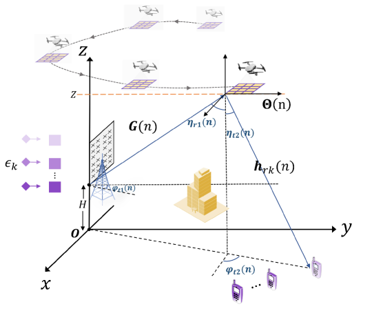
An aerial IRS aided wireless downlink system is considered as shown in Fig.1, where the IRS is hovering above the ground carried by a UAV. The ground base station (BS) is equipped with a uniform planar array (UPA) with M=MxMz𝑀subscript𝑀𝑥subscript𝑀𝑧M=M_{x}M_{z} antennas serving K𝐾K single-antenna ground users. The IRS is also configured with a UPA with Ns=NsxNsysubscript𝑁𝑠subscript𝑁𝑠𝑥subscript𝑁𝑠𝑦N_{s}=N_{sx}N_{sy} reflecting elements. The time of the whole aerial IRS-assisted communications (T𝑇T for total) is divided into NTsubscript𝑁𝑇N_{T} time slots each with duration Δ=T/NTΔ𝑇subscript𝑁𝑇\Delta=T/N_{T}, where n𝑛n is used to denote the current time slot.

The BS with height H𝐻H is located at the origin of the coordinate system, and the antenna array is located on the x-z plane. The space between adjacent antennas is dox=doz=λ2subscript𝑑𝑜𝑥subscript𝑑𝑜𝑧𝜆2d_{ox}=d_{oz}=\frac{\lambda}{2}, where λ𝜆\lambda is the wavelength. The first antenna at the BS is assumed to be located at 𝒄=[0,0,H]T𝒄superscript00𝐻𝑇\bm{c}=[0,0,H]^{T}. Accordingly, the coordinate of the mxthsuperscriptsubscript𝑚𝑥𝑡m_{x}^{th} column, mzthsuperscriptsubscript𝑚𝑧𝑡m_{z}^{th} row antenna is 𝒄¯=𝒄+[0,(mx1)dox,(mz1)doz],mx{1,2,,Mx},mz{1,2,,Mz}formulae-sequence¯𝒄𝒄0subscript𝑚𝑥1subscript𝑑𝑜𝑥subscript𝑚𝑧1subscript𝑑𝑜𝑧formulae-sequencefor-allsubscript𝑚𝑥12subscript𝑀𝑥subscript𝑚𝑧12subscript𝑀𝑧\bar{\bm{c}}=\bm{c}+[0,(m_{x}-1)d_{ox},(m_{z}-1)d_{oz}],\forall m_{x}\in\{1,2,...,M_{x}\},m_{z}\in\{1,2,...,M_{z}\}. The IRS is placed on the xy𝑥𝑦x-y plane with a fixed altitude of Z𝑍Z. We consider the first reflecting element to be at the corner of the IRS, with coordinate 𝒒(n)=[qx(n),qy(n),Z]T𝒒𝑛superscriptsubscript𝑞𝑥𝑛subscript𝑞𝑦𝑛𝑍𝑇\bm{q}(n)=[q_{x}(n),q_{y}(n),Z]^{T} at time slot n𝑛n. Fixed distances dx<λ2subscript𝑑𝑥𝜆2d_{x}<\frac{\lambda}{2} and dy<λ2subscript𝑑𝑦𝜆2d_{y}<\frac{\lambda}{2} are set for separating the adjacent elements [6]. Similarly, the location of the nsthsuperscriptsubscript𝑛𝑠𝑡n_{s}^{th} IRS element is denoted as 𝒒¯(n)=[qx(n)+(nsx1)dx,qy(n)+(nsy1)dy,qz(n)]T,nsx{1,2,,Nsx},nsy{1,2,,Nsy}formulae-sequence¯𝒒𝑛superscriptsubscript𝑞𝑥𝑛subscript𝑛𝑠𝑥1subscript𝑑𝑥subscript𝑞𝑦𝑛subscript𝑛𝑠𝑦1subscript𝑑𝑦subscript𝑞𝑧𝑛𝑇formulae-sequencefor-allsubscript𝑛𝑠𝑥12subscript𝑁𝑠𝑥subscript𝑛𝑠𝑦12subscript𝑁𝑠𝑦\bar{\bm{q}}(n)=[q_{x}(n)+(n_{sx}-1)d_{x},q_{y}(n)+(n_{sy}-1)d_{y},q_{z}(n)]^{T},\forall n_{sx}\in\{1,2,...,N_{sx}\},n_{sy}\in\{1,2,...,N_{sy}\}. The users are assumed to be on the ground, and the coordinate of user k𝑘k is 𝒍k=[kx,ky,0]T,k{1,2,,K}formulae-sequencesubscript𝒍𝑘superscriptsubscript𝑘𝑥subscript𝑘𝑦0𝑇for-all𝑘12𝐾\bm{l}_{k}=[k_{x},k_{y},0]^{T},\forall k\in\{1,2,...,K\}.

The distance between the reference points at the transmit antenna array and the IRS is thus dbr(n)=𝒒(n)𝒄2subscript𝑑𝑏𝑟𝑛subscriptnorm𝒒𝑛𝒄2d_{br}(n)=||\bm{q}(n)-\bm{c}||_{2}, and the distance between the first reflecting element and the kthsuperscript𝑘𝑡k^{th} user is drk(n)=𝒒(n)𝒍k2subscript𝑑𝑟𝑘𝑛subscriptnorm𝒒𝑛subscript𝒍𝑘2d_{rk}(n)=||\bm{q}(n)-\bm{l}_{k}||_{2}. The UAV flight platform is sufficiently high so that the channels between the aerial IRS and the ground nodes are mainly LoS links with a high probability [7]. Due to the dense urban environment, assume that the direct links from the BS to the users are blocked. Without loss of generality, the free space propagation model is considered for measuring the large-scale attenuation. Therefore, the path loss of the BS-IRS channel and the IRS-user k𝑘k channel are ρbr(n)=ρodo2dbr2(n)subscript𝜌𝑏𝑟𝑛subscript𝜌𝑜superscriptsubscript𝑑𝑜2superscriptsubscript𝑑𝑏𝑟2𝑛\rho_{br}(n)=\rho_{o}\frac{d_{o}^{2}}{d_{br}^{2}(n)} and ρrk(n)=ρodo2drk2(n)subscript𝜌𝑟𝑘𝑛subscript𝜌𝑜superscriptsubscript𝑑𝑜2superscriptsubscript𝑑𝑟𝑘2𝑛\rho_{rk}(n)=\rho_{o}\frac{d_{o}^{2}}{d_{rk}^{2}(n)} respectively, where ρosubscript𝜌𝑜\rho_{o} is the reference path loss at a given reference distance do=1msubscript𝑑𝑜1md_{o}=1\rm m.

It is noteworthy that the IRS can be approximated as a UPA since its size is sufficiently small compared with the distance between the communication links. As shown in Fig.2, the angle of departure (AoD) at the BS and the angle of arrival (AoA) are approximately symmetric.

Accordingly, the receiving array response vector at the IRS at time slot n𝑛n is

𝒂R1subscript𝒂𝑅1\displaystyle\bm{a}_{R1} (ηr1(n),φr1(n))subscript𝜂𝑟1𝑛subscript𝜑𝑟1𝑛\displaystyle(\eta_{r1}(n),\varphi_{r1}(n))
=[1,ejϕr1x(n),,ejϕr1x(n)(Nsx1)]Tabsentsuperscript1superscript𝑒𝑗subscriptitalic-ϕ𝑟1𝑥𝑛superscript𝑒𝑗subscriptitalic-ϕ𝑟1𝑥𝑛subscript𝑁𝑠𝑥1𝑇\displaystyle=[1,\;e^{-j\phi_{r1x}(n)},\;...,\;e^{-j\phi_{r1x}(n)(N_{sx}-1)}]^{T}
[1,ejϕr1y(n),,ejϕr1y(n)(Nsy1)]TNs×1,\displaystyle\otimes[1,\;e^{-j\phi_{r1y}(n)},\;...,\;e^{-j\phi_{r1y}(n)(N_{sy}-1)}]^{T}\in\mathbb{C}^{N_{s}\times 1}, (1)

where ϕr1x(n)=2πλdxsinηr1(n)cosφr1(n)subscriptitalic-ϕ𝑟1𝑥𝑛2𝜋𝜆subscript𝑑𝑥subscript𝜂𝑟1𝑛subscript𝜑𝑟1𝑛\phi_{r1x}(n)=\frac{2\pi}{\lambda}d_{x}\sin\eta_{r1}(n)\cos\varphi_{r1}(n) and ϕr1y(n)=2πλdysinηr1(n)sinφr1(n)subscriptitalic-ϕ𝑟1𝑦𝑛2𝜋𝜆subscript𝑑𝑦subscript𝜂𝑟1𝑛subscript𝜑𝑟1𝑛\phi_{r1y}(n)=\frac{2\pi}{\lambda}d_{y}\sin\eta_{r1}(n)\sin\varphi_{r1}(n). The variables ηr1(n)subscript𝜂𝑟1𝑛\eta_{r1}(n) and φr1(n)subscript𝜑𝑟1𝑛\varphi_{r1}(n) denote the elevation and azimuth AoA at time slot n𝑛n at the IRS, and cos(ηr1(n))=ZH𝒒𝒄2subscript𝜂𝑟1𝑛𝑍𝐻subscriptnorm𝒒𝒄2\cos(\eta_{r1}(n))=\frac{Z-H}{||\bm{q}-\bm{c}||_{2}}, sin(φr1(n))=qy𝒒H2subscript𝜑𝑟1𝑛subscript𝑞𝑦subscriptnorm𝒒𝐻2\sin(\varphi_{r1}(n))=\frac{q_{y}}{||\bm{q}-H||_{2}} .

The transmitting array response vector 𝒂T1(n)subscript𝒂𝑇1𝑛\bm{a}_{T1}(n) at the BS antenna array is defined similar to (1). Hence the link between the BS and the IRS is defined as

𝑮𝑮\displaystyle\bm{G} (n)=ρbr(n)ej2πdbr(n)λ𝒂R1(ηr1(n),φr1(n))𝑛subscript𝜌𝑏𝑟𝑛superscript𝑒𝑗2𝜋subscript𝑑𝑏𝑟𝑛𝜆subscript𝒂𝑅1subscript𝜂𝑟1𝑛subscript𝜑𝑟1𝑛\displaystyle(n)=\sqrt{\rho_{br}(n)}e^{-j\frac{2\pi d_{br}(n)}{\lambda}}\bm{a}_{R1}(\eta_{r1}(n),\varphi_{r1}(n))
𝒂T1H(ηt1(n),φt1(n)).superscriptsubscript𝒂𝑇1𝐻subscript𝜂𝑡1𝑛subscript𝜑𝑡1𝑛\displaystyle\bm{a}_{T1}^{H}(\eta_{t1}(n),\varphi_{t1}(n)). (2)

The IRS-user link is expressed as

𝒉rkH(n)=ρrk(n)ej2πdrk(n)λ𝒂T2H(ηt2(n),φt2(n)),superscriptsubscript𝒉𝑟𝑘𝐻𝑛subscript𝜌𝑟𝑘𝑛superscript𝑒𝑗2𝜋subscript𝑑𝑟𝑘𝑛𝜆superscriptsubscript𝒂𝑇2𝐻subscript𝜂𝑡2𝑛subscript𝜑𝑡2𝑛\bm{h}_{rk}^{H}(n)=\sqrt{\rho_{rk}(n)}e^{-j\frac{2\pi d_{rk}(n)}{\lambda}}\bm{a}_{T2}^{H}(\eta_{t2}(n),\varphi_{t2}(n)), (3)

where the transmitting array response vector at the IRS is

𝒂T2subscript𝒂𝑇2\displaystyle\bm{a}_{T2} (ηt2(n),φt2(n))subscript𝜂𝑡2𝑛subscript𝜑𝑡2𝑛\displaystyle(\eta_{t2}(n),\varphi_{t2}(n))
=[1,ejϕt2x(n),,ejϕt2x(n)(Nsx1)]Tabsentsuperscript1superscript𝑒𝑗subscriptitalic-ϕ𝑡2𝑥𝑛superscript𝑒𝑗subscriptitalic-ϕ𝑡2𝑥𝑛subscript𝑁𝑠𝑥1𝑇\displaystyle=[1,\;e^{-j\phi_{t2x}(n)},\;...,\;e^{-j\phi_{t2x}(n)(N_{sx}-1)}]^{T}
[1,ejϕt2y(n),,ejϕt2y(n)(Nsy1)]TNs×1,\displaystyle\otimes[1,\;e^{-j\phi_{t2y}(n)},\;...,\;e^{-j\phi_{t2y}(n)(N_{sy}-1)}]^{T}\in\mathbb{C}^{N_{s}\times 1}, (4)

and ϕt2x(n)=2πλdxsinηt2(n)cosφt2(n)subscriptitalic-ϕ𝑡2𝑥𝑛2𝜋𝜆subscript𝑑𝑥subscript𝜂𝑡2𝑛subscript𝜑𝑡2𝑛\phi_{t2x}(n)=\frac{2\pi}{\lambda}d_{x}\sin\eta_{t2}(n)\cos\varphi_{t2}(n) and ϕt2y(n)=2πλdysinηt2(n)sinφt2(n)subscriptitalic-ϕ𝑡2𝑦𝑛2𝜋𝜆subscript𝑑𝑦subscript𝜂𝑡2𝑛subscript𝜑𝑡2𝑛\phi_{t2y}(n)=\frac{2\pi}{\lambda}d_{y}\sin\eta_{t2}(n)\sin\varphi_{t2}(n).

The phase shift matrix at the IRS is represented as 𝚯(n)=diag{ejθ1(n),ejθ2(n),,ejθNs(n)}𝚯𝑛diagsuperscript𝑒𝑗subscript𝜃1𝑛superscript𝑒𝑗subscript𝜃2𝑛superscript𝑒𝑗subscript𝜃subscript𝑁𝑠𝑛\bm{\Theta}(n)={\rm diag}\{e^{j\theta_{1}(n)},\;e^{j\theta_{2}(n)},...,\;e^{j\theta_{N_{s}}(n)}\}, where 𝜽(n)=[θ1(n),θ2(n),,θNs(n)]T𝜽𝑛superscriptsubscript𝜃1𝑛subscript𝜃2𝑛subscript𝜃𝑁𝑠𝑛𝑇\bm{\theta}(n)=[\theta_{1}(n),\theta_{2}(n),...,\theta_{Ns}(n)]^{T}. θns(n)[0,2π)subscript𝜃subscript𝑛𝑠𝑛02𝜋\theta_{n_{s}}(n)\in[0,2\pi) is the nsthsuperscriptsubscript𝑛𝑠𝑡n_{s}^{th} phase shift of the IRS for ns{1,,Ns}subscript𝑛𝑠1subscript𝑁𝑠n_{s}\in\{1,...,N_{s}\}. The transmit symbol for user k𝑘k is sk(n)subscript𝑠𝑘𝑛s_{k}(n) satisfying 𝔼{|sk(n)|2}=1𝔼superscriptsubscript𝑠𝑘𝑛21\mathbb{E}\{|s_{k}(n)|^{2}\}=1, and 𝒘k(n)M×1subscript𝒘𝑘𝑛superscript𝑀1\bm{w}_{k}(n)\in\mathbb{C}^{M\times 1} is the corresponding transmit beamforming vector. As such, the transmitted signal at the BS can be expressed as

𝒙(n)=k=1K𝒘k(n)sk(n),𝒙𝑛superscriptsubscript𝑘1𝐾subscript𝒘𝑘𝑛subscript𝑠𝑘𝑛\bm{x}(n)=\sum_{k=1}^{K}\bm{w}_{k}(n)s_{k}(n), (5)

where we set the constraint that, the transmit power for each user is less than or equal to Posubscript𝑃𝑜P_{o},

𝒘k(n)2Po,k{1,,K}.formulae-sequencesuperscriptnormsubscript𝒘𝑘𝑛2subscript𝑃𝑜for-all𝑘1𝐾||\bm{w}_{k}(n)||^{2}\leq P_{o},\;\forall k\in\{1,...,K\}. (6)

Assuming the direct links are unavailable, the received signal at user k𝑘k can be expressed as

yk(n)=𝒉rkH(n)𝚯(n)𝑮(n)𝒙n+uk(n),subscript𝑦𝑘𝑛superscriptsubscript𝒉𝑟𝑘𝐻𝑛𝚯𝑛𝑮𝑛subscript𝒙𝑛subscript𝑢𝑘𝑛y_{k}(n)=\bm{h}_{rk}^{H}(n)\bm{\Theta}(n)\bm{G}(n)\bm{x}_{n}+u_{k}(n), (7)

where uk(n)𝒞𝒩(0,σo2)similar-tosubscript𝑢𝑘𝑛𝒞𝒩0superscriptsubscript𝜎𝑜2u_{k}(n)\sim\mathcal{CN}(0,\sigma_{o}^{2}) represents the additive white Gaussian noise (AWGN) at the receiver of user k𝑘k. For simplicity, the channel for user k𝑘k can be denoted as 𝒉kH(n)=𝒉rkH(n)𝚯(n)𝑮(n)superscriptsubscript𝒉𝑘𝐻𝑛superscriptsubscript𝒉𝑟𝑘𝐻𝑛𝚯𝑛𝑮𝑛\bm{h}_{k}^{H}(n)=\bm{h}_{rk}^{H}(n)\bm{\Theta}(n)\bm{G}(n), and yk(n)=𝒉kH(n)𝒙(n)+uk(n)subscript𝑦𝑘𝑛superscriptsubscript𝒉𝑘𝐻𝑛𝒙𝑛subscript𝑢𝑘𝑛y_{k}(n)=\bm{h}_{k}^{H}(n)\bm{x}(n)+u_{k}(n).

II-B The Age of Information Model

In this model, we assume K𝐾K data streams at the BS corresponding to K𝐾K users, where a status update data packet of stream k𝑘k arrives at the base station with a probability ϵksubscriptitalic-ϵ𝑘\epsilon_{k} at each time slot, and we define pk(n){0,1}subscript𝑝𝑘𝑛01p_{k}(n)\in\{0,1\} to indicate whether there is a packet arriving, with Pr[pk(n)=1]=ϵk𝑃𝑟delimited-[]subscript𝑝𝑘𝑛1subscriptitalic-ϵ𝑘Pr[p_{k}(n)=1]=\epsilon_{k}. Ak(n)subscript𝐴𝑘𝑛A_{k}(n) is used to denote the AoI of the targeted user k𝑘k at time slot n𝑛n. We use a binary scheduling indicator αk(n)=1subscript𝛼𝑘𝑛1\alpha_{k}(n)=1 when the kthsuperscript𝑘𝑡k^{th} data stream is scheduled otherwise it is equal to 00. We furthur assume that there is only one available channel at each time slot, such that

αk(n){0,1},n.subscript𝛼𝑘𝑛01for-all𝑛\alpha_{k}(n)\in\{0,1\},\;\forall n. (8)
k=1Kαk(n)1,n.superscriptsubscript𝑘1𝐾subscript𝛼𝑘𝑛1for-all𝑛\sum_{k=1}^{K}\alpha_{k}(n)\leq 1,\;\forall n.\vspace*{-0.3\baselineskip} (9)

The AoI will increase linearly without newly updated data packets successfully received by the targeted receiver, and otherwise it is determined by the packet queuing time zk(n)subscript𝑧𝑘𝑛z_{k}(n), with Ak(n+1)=zk(n)+1subscript𝐴𝑘𝑛1subscript𝑧𝑘𝑛1A_{k}(n+1)=z_{k}(n)+1. Following [12] and [13], the system time zk(n)subscript𝑧𝑘𝑛z_{k}(n) is given by

zk(n+1)={0,ifαk(n+1)=1,k,nzk(n)+1,otherwise.z_{k}(n+1)=\left\{\begin{aligned} &0,&if\,\alpha_{k}(n+1)=1,\forall k,n\\ &z_{k}(n)+1,&otherwise.\end{aligned}\right.\vspace*{-0.2\baselineskip} (10)

We define another binary variable ξk(n)subscript𝜉𝑘𝑛\xi_{k}(n) indicating the available packet status with the value equalling to 111 when there is a available packet at stream k𝑘k. Otherwise ξk(n)subscript𝜉𝑘𝑛\xi_{k}(n) only turns to 00 with a successful delivery at last time slot and no new packet. A packet is delivered successfully if the scheduled stream has an available packet and the received signal-to-noise ratio (SNR) is no less than the threshold value. Therefore the indicator ξk(n)subscript𝜉𝑘𝑛\xi_{k}(n) can be expressed as

ξk(n+1)=pk(n+1)+ξk(n)(1αk(n))(1pk(n+1)),subscript𝜉𝑘𝑛1subscript𝑝𝑘𝑛1subscript𝜉𝑘𝑛1subscript𝛼𝑘𝑛1subscript𝑝𝑘𝑛1\xi_{k}(n+1)=p_{k}(n+1)+\xi_{k}(n)(1-\alpha_{k}(n))(1-p_{k}(n+1)), (11)

where γthsubscript𝛾𝑡\gamma_{th} denotes the threshold SNR. As a result, the AoI can be expressed as

Ak(n+1)=zk(n)αk(n)ξk(n)+Ak(n)[(1αk(n))ξk(n)\displaystyle A_{k}(n+1)=\,z_{k}(n)\alpha_{k}(n)\xi_{k}(n)+A_{k}(n)[(1-\alpha_{k}(n))\xi_{k}(n)
+αk(n)(1ξk(n))+(1αk(n))(1ξk(n))]+1,\displaystyle+\alpha_{k}(n)(1-\xi_{k}(n))+(1-\alpha_{k}(n))(1-\xi_{k}(n))]+1,\vspace*{-0.5\baselineskip} (12)

with the SNR constraint

γk(n)αk(n)ξk(n)γth,subscript𝛾𝑘𝑛subscript𝛼𝑘𝑛subscript𝜉𝑘𝑛subscript𝛾𝑡\gamma_{k}(n)\geq\alpha_{k}(n)\xi_{k}(n)\gamma_{th},\vspace*{-0.2\baselineskip} (13)

where the received SNR is

γk(n)=|𝒉kH(n)𝒘k(n)|2σo2.subscript𝛾𝑘𝑛superscriptsuperscriptsubscript𝒉𝑘𝐻𝑛subscript𝒘𝑘𝑛2superscriptsubscript𝜎𝑜2\gamma_{k}(n)=\frac{|\bm{h}_{k}^{H}(n)\bm{w}_{k}(n)|^{2}}{\sigma_{o}^{2}}.\vspace*{-0.5\baselineskip} (14)

II-C Problem Formulation

To meet the demands of real-time communications and guarantee the freshness of information, the aim of this paper is to minimize the weighted sum AoI of all K𝐾K users. We propose an algorithm to optimize the UAV trajectory, scheduling scheme at the BS and active and passive beamforming design. The optimization problem is formulated as (P1),

(P1)::P1absent\displaystyle\mathrm{(P1)}:\; min𝒒(n),αk(n),𝒘k(n),𝚯(n)k=1KbkAkNT\displaystyle\min_{\bm{q}(n),\alpha_{k}(n),\atop\bm{w}_{k}(n),\bm{\Theta}(n)}\sum_{k=1}^{K}b_{k}A_{k}^{N_{T}} (15)
𝒔.𝒕.formulae-sequence𝒔𝒕\displaystyle\bm{s.t.}\quad (6),(8),(9),(13)68913\displaystyle(\ref{Cons_pow}),(\ref{Cons_alpha}),(\ref{Cons_channel}),(\ref{Cons_SINR})
qz(n)=Z,n{1,,NT},formulae-sequencesubscript𝑞𝑧𝑛𝑍for-all𝑛1subscript𝑁𝑇\displaystyle q_{z}(n)=Z,\;\forall n\in\{1,...,N_{T}\}, (15a)
𝒒(n)𝒒(n1)vmaxΔ,norm𝒒𝑛𝒒𝑛1subscript𝑣𝑚𝑎𝑥Δ\displaystyle||\bm{q}(n)-\bm{q}(n-1)||\leq v_{max}\Delta, (15b)
θns(n)[0,2π),ns{1,,Ns},formulae-sequencesubscript𝜃subscript𝑛𝑠𝑛02𝜋for-allsubscript𝑛𝑠1subscript𝑁𝑠\displaystyle\theta_{n_{s}}(n)\in[0,2\pi),\forall n_{s}\in\{1,...,N_{s}\},\vspace*{-0.5\baselineskip} (15c)

where bksubscript𝑏𝑘b_{k} is the priority for user k𝑘k, and AkNTsuperscriptsubscript𝐴𝑘subscript𝑁𝑇A_{k}^{N_{T}} denotes the sum AoI of user k𝑘k for NTsubscript𝑁𝑇N_{T} total time slots.

Since the AoI will keep increasing linearly without newly updated data packets, the problem of minimizing sum AoI becomes maximizing the AoI reduction at each time slot. Specifically, the stream with the worst weighted AoI should be scheduled if there is an available packet to be delivered. Hence the original problem (P1) can be reformulated as

(P2)::P2absent\displaystyle\mathrm{(P2)}:\; max𝒒(n),αk(n),𝒘k(n),𝚯(n)k=1KbkAk(n)αk(n)ξk(n)\displaystyle\max_{\bm{q}(n),\alpha_{k}(n),\atop\bm{w}_{k}(n),\bm{\Theta}(n)}\sum_{k=1}^{K}b_{k}A_{k}(n)\alpha_{k}(n)\xi_{k}(n) (16)
𝒔.𝒕.formulae-sequence𝒔𝒕\displaystyle\bm{s.t.}\quad (6),(8),(9),(13),(15a),(15b),(15c).6891315a15b15c\displaystyle(\ref{Cons_pow}),(\ref{Cons_alpha}),(\ref{Cons_channel}),(\ref{Cons_SINR}),(\ref{Cons_UAValti}),(\ref{Cons_velocity}),(\ref{Cons_phase}).\vspace*{-0.5\baselineskip}

However, the problem is intractable because of i) the coupling of variables 𝒒(n),αk(n),𝒘k(n)𝒒𝑛subscript𝛼𝑘𝑛subscript𝒘𝑘𝑛\bm{q}(n),\,\alpha_{k}(n),\,\bm{w}_{k}(n) and 𝚯(n)𝚯𝑛\bm{\Theta}(n); and ii) the non-convexity of constraints (8) and (13). The proposed iterative solution based on SCA algorithm is derived and elaborated as follows.

III Proposed Solutions

In this section, the proposed algorithm is given as follows. To decouple the variables, the problem is solved alternatively, where the active and passive beamforming are jointly designed for maximizing the array gain with fixed UAV location, and given the optimized beamforming design, the scheduling policy is updated with UAV trajectory optimization. The SCA algorithm is an efficient approach to deal with the non-convexity of the AoI constraints.

III-A Joint Active and Passive Beamforming Design

To maximize the AoI reduction at each time slot, the received SNR should be maximized to satisfy constraint (13). Therefore, it is equivalent to maximizing the array gains of the UPAs at the BS and IRS respectively through digital beamforming and IRS phase shift design.

Given the UAV location, the optimal transmit beamforming can be determined by Maximum Ratio Transmission (MRT) to align with the transmitting array response vector at the BS, which is given by

𝒘k(n)=Pk𝒂T1(ηt1(n),φt1(n))M.subscript𝒘𝑘𝑛subscript𝑃𝑘subscript𝒂𝑇1subscript𝜂𝑡1𝑛subscript𝜑𝑡1𝑛𝑀\bm{w}_{k}(n)=\sqrt{P_{k}}\frac{\bm{a}_{T1}(\eta_{t1}(n),\varphi_{t1}(n))}{\sqrt{M}}.\vspace*{-0.5\baselineskip} (17)

The array gain at the IRS is expressed as

|nsx=1Nsxnsy=1Nsyej(θnsx,nsy(n)+μnsx(n)+μnsy(n))|,superscriptsubscriptsubscript𝑛𝑠𝑥1subscript𝑁𝑠𝑥superscriptsubscriptsubscript𝑛𝑠𝑦1subscript𝑁𝑠𝑦superscript𝑒𝑗subscript𝜃subscript𝑛𝑠𝑥subscript𝑛𝑠𝑦𝑛subscript𝜇subscript𝑛𝑠𝑥𝑛subscript𝜇subscript𝑛𝑠𝑦𝑛\large\displaystyle\Big{|}\sum\limits_{n_{sx}=1}^{N_{sx}}\sum\limits_{n_{sy}=1}^{N_{sy}}e^{j\left(\theta_{n_{sx},n_{sy}}(n)+\mu_{n_{sx}}(n)+\mu_{n_{sy}}(n)\right)}\Big{|},\vspace*{-0.5\baselineskip} (18)

where μnsx(n)=(nsx1)(ϕt2x(n)ϕr1x(n))subscript𝜇subscript𝑛𝑠𝑥𝑛subscript𝑛𝑠𝑥1subscriptitalic-ϕ𝑡2𝑥𝑛subscriptitalic-ϕ𝑟1𝑥𝑛\mu_{n_{sx}}(n)=(n_{sx}-1)(\phi_{t2x}(n)-\phi_{r1x}(n)) and μnsy(n)=(nsy1)(ϕt2y(n)ϕr1y(n))subscript𝜇subscript𝑛𝑠𝑦𝑛subscript𝑛𝑠𝑦1subscriptitalic-ϕ𝑡2𝑦𝑛subscriptitalic-ϕ𝑟1𝑦𝑛\mu_{n_{sy}}(n)=(n_{sy}-1)(\phi_{t2y}(n)-\phi_{r1y}(n)).

Applying the triangle inequality,

|nsx=1Nsxnsy=1Nsyej(θnsx,nsy(n)+μnsx(n)+μnsy(n))|superscriptsubscriptsubscript𝑛𝑠𝑥1subscript𝑁𝑠𝑥superscriptsubscriptsubscript𝑛𝑠𝑦1subscript𝑁𝑠𝑦superscript𝑒𝑗subscript𝜃subscript𝑛𝑠𝑥subscript𝑛𝑠𝑦𝑛subscript𝜇subscript𝑛𝑠𝑥𝑛subscript𝜇subscript𝑛𝑠𝑦𝑛\displaystyle\Big{|}\sum\limits_{n_{sx}=1}^{N_{sx}}\sum\limits_{n_{sy}=1}^{N_{sy}}e^{j\left(\theta_{n_{sx},n_{sy}}(n)+\mu_{n_{sx}}(n)+\mu_{n_{sy}}(n)\right)}\Big{|}
\displaystyle\leq |ejθ1,1(n)|++|ej(θnsx,nsy(n)+μnsx(n)+μnsy(n))|+superscript𝑒𝑗subscript𝜃11𝑛limit-fromsuperscript𝑒𝑗subscript𝜃subscript𝑛𝑠𝑥subscript𝑛𝑠𝑦𝑛subscript𝜇subscript𝑛𝑠𝑥𝑛subscript𝜇subscript𝑛𝑠𝑦𝑛\displaystyle\big{|}e^{j\theta_{1,1}(n)}\big{|}+\dots+\big{|}e^{j\left(\theta_{n_{sx},n_{sy}}(n)+\mu_{n_{sx}}(n)+\mu_{n_{sy}}(n)\right)}\big{|}+
+|ej(θNsx,Nsy(n)+μNsx(n)+μNsy(n))|=Ns,superscript𝑒𝑗subscript𝜃subscript𝑁𝑠𝑥subscript𝑁𝑠𝑦𝑛subscript𝜇subscript𝑁𝑠𝑥𝑛subscript𝜇subscript𝑁𝑠𝑦𝑛subscript𝑁𝑠\displaystyle\dots+\big{|}e^{j\left(\theta_{N_{sx},N_{sy}}(n)+\mu_{N_{sx}}(n)+\mu_{N_{sy}}(n)\right)}\big{|}=N_{s},\vspace*{-0.5\baselineskip} (19)

where the equality holds with

θnsx,nsy(n)=(μnsx(n)+μnsy(n))subscript𝜃subscript𝑛𝑠𝑥subscript𝑛𝑠𝑦𝑛subscript𝜇subscript𝑛𝑠𝑥𝑛subscript𝜇subscript𝑛𝑠𝑦𝑛\displaystyle\theta_{n_{sx},n_{sy}}(n)=-(\mu_{n_{sx}}(n)+\mu_{n_{sy}}(n))
=\displaystyle= 2πλ[dx(nsx1)(sinηt2(n)cosφt2(n)sinηr1(n)cosφr1(n))\displaystyle-\frac{2\pi}{\lambda}\Big{[}d_{x}(n_{sx}-1)(\sin\eta_{t2}(n)\cos\varphi_{t2}(n)-\sin\eta_{r1}(n)\cos\varphi_{r1}(n))
dy(nsy1)(sinηt2(n)sinφt2(n)sinηr1(n)sinφr1)(n)].\displaystyle-d_{y}(n_{sy}-1)(\sin\eta_{t2}(n)\sin\varphi_{t2}(n)-\sin\eta_{r1}(n)\sin\varphi_{r1})(n)\Big{]}.\vspace*{-0.5\baselineskip} (20)

III-B Scheduling and UAV Trajectory Optimization

With the above optimal active and passive beamforming strategies, the received SNR at user k𝑘k can be obtained as

γ¯k(n)=subscript¯𝛾𝑘𝑛absent\displaystyle\bar{\gamma}_{k}(n)= ρrk(n)ρbr(n)PoNs2Mσo2subscript𝜌𝑟𝑘𝑛subscript𝜌𝑏𝑟𝑛subscript𝑃𝑜superscriptsubscript𝑁𝑠2𝑀superscriptsubscript𝜎𝑜2\displaystyle\frac{\rho_{rk}(n)\rho_{br}(n)P_{o}N_{s}^{2}M}{\sigma_{o}^{2}}
=ρo2do4PoNs2Mdrk2(n)dbr2(n)σo2absentsuperscriptsubscript𝜌𝑜2superscriptsubscript𝑑𝑜4subscript𝑃𝑜superscriptsubscript𝑁𝑠2𝑀superscriptsubscript𝑑𝑟𝑘2𝑛superscriptsubscript𝑑𝑏𝑟2𝑛superscriptsubscript𝜎𝑜2\displaystyle=\frac{\rho_{o}^{2}d_{o}^{4}P_{o}N_{s}^{2}M}{d_{rk}^{2}(n)d_{br}^{2}(n)\sigma_{o}^{2}}
=ρo2do4PoNs2M𝒒(n)𝒍k2𝒒(n)𝒄2σo2,absentsuperscriptsubscript𝜌𝑜2superscriptsubscript𝑑𝑜4subscript𝑃𝑜superscriptsubscript𝑁𝑠2𝑀superscriptnorm𝒒𝑛subscript𝒍𝑘2superscriptnorm𝒒𝑛𝒄2superscriptsubscript𝜎𝑜2\displaystyle=\frac{\rho_{o}^{2}d_{o}^{4}P_{o}N_{s}^{2}M}{||\bm{q}(n)-\bm{l}_{k}||^{2}||\bm{q}(n)-\bm{c}||^{2}\sigma_{o}^{2}}, (21)

which is only related to the UAV location 𝒒(n)𝒒𝑛\bm{q}(n). Therefore, the problem (P2) can be reformulated as

(P3)::P3absent\displaystyle\mathrm{(P3)}:\; max𝒒(n),αk(n)k=1KbkAk(n)αk(n)ξk(n)subscript𝒒𝑛subscript𝛼𝑘𝑛superscriptsubscript𝑘1𝐾subscript𝑏𝑘subscript𝐴𝑘𝑛subscript𝛼𝑘𝑛subscript𝜉𝑘𝑛\displaystyle\max_{\bm{q}(n),\alpha_{k}(n)}\sum_{k=1}^{K}b_{k}A_{k}(n)\alpha_{k}(n)\xi_{k}(n) (22)
𝒔.𝒕.formulae-sequence𝒔𝒕\displaystyle\bm{s.t.}\quad ρo2do4PoNs2M𝒒(n)𝒍k2𝒒(n)𝒄2σo2αk(n)ξk(n)γthsuperscriptsubscript𝜌𝑜2superscriptsubscript𝑑𝑜4subscript𝑃𝑜superscriptsubscript𝑁𝑠2𝑀superscriptnorm𝒒𝑛subscript𝒍𝑘2superscriptnorm𝒒𝑛𝒄2superscriptsubscript𝜎𝑜2subscript𝛼𝑘𝑛subscript𝜉𝑘𝑛subscript𝛾𝑡\displaystyle\frac{\rho_{o}^{2}d_{o}^{4}P_{o}N_{s}^{2}M}{||\bm{q}(n)-\bm{l}_{k}||^{2}||\bm{q}(n)-\bm{c}||^{2}\sigma_{o}^{2}}\geq\alpha_{k}(n)\xi_{k}(n)\gamma_{th} (22a)
(8),(9),(15a),(15b),8915a15b\displaystyle(\ref{Cons_alpha}),(\ref{Cons_channel}),(\ref{Cons_UAValti}),(\ref{Cons_velocity}),

where the objective function and the available channel constraint (9) are linear, and the scheduling indicator constraint (8) can be relaxed as

αk(n)[0,1],subscript𝛼𝑘𝑛01\alpha_{k}(n)\in[0,1],\vspace*{-0.5\baselineskip} (23)

which is convex. The UAV altitude constraint (15a) can be expressed as

𝒒T(n)𝜺=Z,superscript𝒒T𝑛𝜺𝑍\bm{q}^{\rm T}(n)\bm{\varepsilon}=Z,\vspace*{-0.5\baselineskip} (24)

where 𝜺=[0,0,1]T𝜺superscript001𝑇\bm{\varepsilon}=[0,0,1]^{T}. However, problem (P3) is still non-convex due to the constraint (22a). To tackle the non-convexity, the SCA algorithm is applied iteratively. First, slack variables rrk(n)subscript𝑟𝑟𝑘𝑛r_{rk}(n) and rbr(n)subscript𝑟𝑏𝑟𝑛r_{br}(n) are introduced as the upper bound of drk2(n)superscriptsubscript𝑑𝑟𝑘2𝑛d_{rk}^{2}(n) and dbr2(n)superscriptsubscript𝑑𝑏𝑟2𝑛d_{br}^{2}(n) respectively, which can be described as

𝒒(n)𝒍k2rrk(n),superscriptnorm𝒒𝑛subscript𝒍𝑘2subscript𝑟𝑟𝑘𝑛\displaystyle||\bm{q}(n)-\bm{l}_{k}||^{2}\leq r_{rk}(n), (25)
𝒒(n)𝒄2rbr(n).superscriptnorm𝒒𝑛𝒄2subscript𝑟𝑏𝑟𝑛\displaystyle||\bm{q}(n)-\bm{c}||^{2}\leq r_{br}(n).\vspace*{-0.5\baselineskip} (26)

Thus, the lower bound of the γ¯k(n)subscript¯𝛾𝑘𝑛\bar{\gamma}_{k}(n) can be expressed as

γ¯k(n)ρo2do4PoNs2Mrrk(n)rbr(n)σo2=Γk(n)rrk(n)rbr(n),subscript¯𝛾𝑘𝑛superscriptsubscript𝜌𝑜2superscriptsubscript𝑑𝑜4subscript𝑃𝑜superscriptsubscript𝑁𝑠2𝑀subscript𝑟𝑟𝑘𝑛subscript𝑟𝑏𝑟𝑛superscriptsubscript𝜎𝑜2subscriptΓ𝑘𝑛subscript𝑟𝑟𝑘𝑛subscript𝑟𝑏𝑟𝑛\bar{\gamma}_{k}(n)\geq\frac{\rho_{o}^{2}d_{o}^{4}P_{o}N_{s}^{2}M}{r_{rk}(n)r_{br}(n)\sigma_{o}^{2}}=\frac{\Gamma_{k}(n)}{r_{rk}(n)r_{br}(n)},\vspace*{-0.2\baselineskip} (27)

where Γk(n)=ρo2do4PoNs2Mσo2subscriptΓ𝑘𝑛superscriptsubscript𝜌𝑜2superscriptsubscript𝑑𝑜4subscript𝑃𝑜superscriptsubscript𝑁𝑠2𝑀superscriptsubscript𝜎𝑜2\Gamma_{k}(n)=\frac{\rho_{o}^{2}d_{o}^{4}P_{o}N_{s}^{2}M}{\sigma_{o}^{2}}, and the SNR constraint is obtained as

Γk(n)rrk(n)rbr(n)αk(n)ξk(n)γth,subscriptΓ𝑘𝑛subscript𝑟𝑟𝑘𝑛subscript𝑟𝑏𝑟𝑛subscript𝛼𝑘𝑛subscript𝜉𝑘𝑛subscript𝛾𝑡\frac{\Gamma_{k}(n)}{r_{rk}(n)r_{br}(n)}\geq\alpha_{k}(n)\xi_{k}(n)\gamma_{th},\vspace*{-0.5\baselineskip} (28)

which is equivalent to

Γk(n)ξk(n)γthrrk(n)rbr(n)αk(n).subscriptΓ𝑘𝑛subscript𝜉𝑘𝑛subscript𝛾𝑡subscript𝑟𝑟𝑘𝑛subscript𝑟𝑏𝑟𝑛subscript𝛼𝑘𝑛\frac{\Gamma_{k}(n)}{\xi_{k}(n)\gamma_{th}}\geq r_{rk}(n)r_{br}(n)\alpha_{k}(n). (29)

To tackle the coupling between the variables, the logarithm is taken at both sides. Then, we compute the first-order Taylor series of the right-hand side (RHS) in the ithsuperscript𝑖𝑡i^{th} iteration in (29), which results in

lnΓk(n)lnξk(n)γthlnrrk(n)+lnrbr(n)+lnαk(n)subscriptΓ𝑘𝑛subscript𝜉𝑘𝑛subscript𝛾𝑡subscript𝑟𝑟𝑘𝑛subscript𝑟𝑏𝑟𝑛subscript𝛼𝑘𝑛\displaystyle\ln{\Gamma_{k}(n)}-\ln\xi_{k}(n)\gamma_{th}\geq\ln r_{rk}(n)+\ln r_{br}(n)+\ln\alpha_{k}(n)
=\displaystyle= lnrrk(i1)(n)+lnrbr(i1)(n)+lnαk(i1)(n)superscriptsubscript𝑟𝑟𝑘𝑖1𝑛superscriptsubscript𝑟𝑏𝑟𝑖1𝑛superscriptsubscript𝛼𝑘𝑖1𝑛\displaystyle\ln{r_{rk}^{(i-1)}(n)}+\ln{r_{br}^{(i-1)}(n)}+\ln{\alpha_{k}^{(i-1)}(n)}
+rrk(i)(n)rrk(i1)(n)rrk(i1)(n)+rbr(i)(n)rbr(i1)(n)rbr(i1)(n)superscriptsubscript𝑟𝑟𝑘𝑖𝑛superscriptsubscript𝑟𝑟𝑘𝑖1𝑛superscriptsubscript𝑟𝑟𝑘𝑖1𝑛superscriptsubscript𝑟𝑏𝑟𝑖𝑛superscriptsubscript𝑟𝑏𝑟𝑖1𝑛superscriptsubscript𝑟𝑏𝑟𝑖1𝑛\displaystyle+\frac{r_{rk}^{(i)}(n)-r_{rk}^{(i-1)}(n)}{r_{rk}^{(i-1)}(n)}+\frac{r_{br}^{(i)}(n)-r_{br}^{(i-1)}(n)}{r_{br}^{(i-1)}(n)}
+αk(i)(n)αk(i1)(n)αk(i1)(n)=r^rk(i)(n)+r^br(i)(n)+αk^(i)(n),superscriptsubscript𝛼𝑘𝑖𝑛superscriptsubscript𝛼𝑘𝑖1𝑛superscriptsubscript𝛼𝑘𝑖1𝑛superscriptsubscript^𝑟𝑟𝑘𝑖𝑛superscriptsubscript^𝑟𝑏𝑟𝑖𝑛superscript^subscript𝛼𝑘𝑖𝑛\displaystyle+\frac{\alpha_{k}^{(i)}(n)-\alpha_{k}^{(i-1)}(n)}{\alpha_{k}^{(i-1)}(n)}=\hat{r}_{rk}^{(i)}(n)+\hat{r}_{br}^{(i)}(n)+\hat{\alpha_{k}}^{(i)}(n), (30)

where (i1)𝑖1(i-1) denotes the value in the i1th𝑖superscript1𝑡i-1^{th} iteration. It is noteworthy that αk(n)subscript𝛼𝑘𝑛\alpha_{k}(n) cannot be equal to 00 for validity, so that constraint (23) becomes

αk(n)(0,1].subscript𝛼𝑘𝑛01\alpha_{k}(n)\in(0,1].\vspace*{-0.5\baselineskip} (31)

Hence the problem (P3) in the ithsuperscript𝑖𝑡i^{th} iteration becomes

(P3.1):max𝒒(n),αk(n),rrk(n),rbr(n)k=1KbkAk(n)αk(n)ξk(n)\displaystyle\mathrm{(P3.1)}:\;\max_{\bm{q}(n),\alpha_{k}(n),\atop r_{rk}(n),r_{br}(n)}\sum_{k=1}^{K}b_{k}A_{k}(n)\alpha_{k}(n)\xi_{k}(n) (32)
𝒔.𝒕.formulae-sequence𝒔𝒕\displaystyle\bm{s.t.}\; r^rk(i)(n)+r^br(i)(n)+α^k(i)(n)lnΓk(n)lnαk(n)ξk(n)γthsuperscriptsubscript^𝑟𝑟𝑘𝑖𝑛superscriptsubscript^𝑟𝑏𝑟𝑖𝑛superscriptsubscript^𝛼𝑘𝑖𝑛subscriptΓ𝑘𝑛subscript𝛼𝑘𝑛subscript𝜉𝑘𝑛subscript𝛾𝑡\displaystyle\hat{r}_{rk}^{(i)}(n)+\hat{r}_{br}^{(i)}(n)+\hat{\alpha}_{k}^{(i)}(n)\leq\ln{\Gamma_{k}(n)}-\ln\alpha_{k}(n)\xi_{k}(n)\gamma_{th} (32a)
(9),(15b),(31),(24),(25),(26),915b31242526\displaystyle(\ref{Cons_channel}),(\ref{Cons_velocity}),(\ref{Cons_rela_alpha_0}),(\ref{Cons_UAValti_cvx}),(\ref{Cons_slack1}),(\ref{Cons_slack2}),

which is a convex problem and can be efficiently solved using standard optimization solver such as CVX. Finally, the SCA based algorithm is summarized in Algorithm 1.

Algorithm 1 SCA based joint scheduling and UAV trajectory optimization
1:Initialize 𝒒(n),αk(n),rrk(n),rbr(n)k{1,..,K}\bm{q}(n),\alpha_{k}(n),r_{rk}(n),r_{br}(n)\;\forall k\in\{1,..,K\}, n{1,,NT}.for-all𝑛1subscript𝑁𝑇\forall n\in\{1,...,N_{T}\}. Set iteration index i=1𝑖1i=1.
2:repeat
3:     Update 𝒒(n),αk(n),rrk(n),rbr(n)𝒒𝑛subscript𝛼𝑘𝑛subscript𝑟𝑟𝑘𝑛subscript𝑟𝑏𝑟𝑛\bm{q}(n),\alpha_{k}(n),r_{rk}(n),r_{br}(n) by solving problem (P3.1).
4:until Convergence.
5:Output 𝒒(n),αk(n)𝒒𝑛subscript𝛼𝑘𝑛\bm{q}(n),\alpha_{k}(n).

IV Numerical Results

In this section, the results of the numerical simulations are provided to demonstrate the performance improvement of the proposed algorithm. A base station with height H=25m𝐻25mH=25{\rm\,m} is considered, with a M=4×4𝑀44M=4\times 4 UPA. K=6𝐾6K=6 stationary ground users are located at 𝒍1=[200,100,0]Tmsubscript𝒍1superscript2001000Tm\bm{l}_{1}=[200,-100,0]^{\rm T}{\rm m}, 𝒍2=[150,300,0]Tmsubscript𝒍2superscript1503000Tm\bm{l}_{2}=[150,300,0]^{\rm T}{\rm m}, 𝒍3=[320,280,0]Tmsubscript𝒍3superscript3202800Tm\bm{l}_{3}=[320,-280,0]^{\rm T}{\rm m}, 𝒍4=[490,20,0]Tmsubscript𝒍4superscript490200Tm\bm{l}_{4}=[490,20,0]^{\rm T}{\rm m}, 𝒍5=[50,200,0]Tmsubscript𝒍5superscript502000Tm\bm{l}_{5}=[50,-200,0]^{\rm T}{\rm m}, 𝒍6=[730,30,0]Tmsubscript𝒍6superscript730300Tm\bm{l}_{6}=[730,30,0]^{\rm T}{\rm m} respectively. The maximum transmit power for each user is set to be Po=1Wsubscript𝑃𝑜1WP_{o}=1{\rm W}, and the noise power is σo2=110dBmsuperscriptsubscript𝜎𝑜2110dBm\sigma_{o}^{2}=-110\,{\rm dBm}. According to the carrier frequency fc=2.4GHzsubscript𝑓𝑐2.4GHzf_{c}=2.4\,{\rm GHz}, the reference channel power gain is set to be ρo=40dBsubscript𝜌𝑜40dB\rho_{o}=-40\,{\rm dB}. Besides, the distance between the adjacent elements at the IRS is dx=dy=λ/10subscript𝑑𝑥subscript𝑑𝑦𝜆10d_{x}=d_{y}=\lambda/10. The maximum flying velocity is set as vmax=5m/ssubscript𝑣𝑚𝑎𝑥5msv_{max}=5\,{\rm m/s}. We consider NT=40subscript𝑁𝑇40N_{T}=40 simulation time slots in total, with each slot lasting Δ=0.1sΔ0.1s\Delta=0.1\,{\rm s}. The initial location of the UAV is set as 𝒒=[0,0,Z]T𝒒superscript00𝑍T\bm{q}=[0,0,Z]^{\rm T}, where the flight altitude Z𝑍Z is set as different values for comparison.

Fig.3 plots AoI for NT=40subscript𝑁𝑇40N_{T}=40 time slots of the 666 users. The height of the aerial IRS is fixed as Z=100m𝑍100mZ=100\,{\rm m}. The number of IRS elements is assumed to be Ns=550subscript𝑁𝑠550N_{s}=550, and the SNR threshold is set as γth=25dBsubscript𝛾𝑡25dB\gamma_{th}=25{\rm\,dB}. It can be seen that the AoI would increase linearly without the corresponding stream being scheduled. Therefore, when the AoI is high, it will drop due to packet scheduling and and transmission by the base station.

Refer to caption
Figure 2: AoI performance of 6 users.

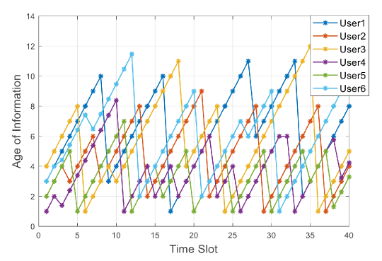
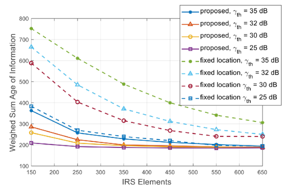
Fig.4 illustrates the weighted sum AoI for 40 time slots in total versus the number of IRS elements. The proposed algorithm shows significantly better performance than the fixed location scheme for the UAV at [0,0,100m]Tsuperscript00100mT[0,0,100\rm m]^{\rm T} in terms of information freshness. Simultaneously, the weighted sum AoI decreases with the increase of IRS elements Nssubscript𝑁𝑠N_{s}, from 150150150 to 650650650, converging to the optimal value. Thus, with larger-scale IRS, the communication link can be enhanced with the proposed algorithm. Besides, different levels of the threshold value of SNR are considered, namely γth=25dB,30dB,32dBsubscript𝛾𝑡25dB30dB32dB\gamma_{th}=25\,{\rm dB},30\,{\rm dB},32\,{\rm dB} and 35dB35dB35\,{\rm dB} respectively, and it can be seen that with higher γthsubscript𝛾𝑡\gamma_{th}, the freshness of the received packets becomes worse.

Refer to caption
Figure 3: Weighted sum AoI versus number of IRS elements Nssubscript𝑁𝑠N_{s}.

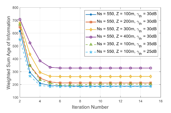
The convergence behavior with iteration number from 222 to 151515 is highlighted in Fig.5. We compare the AoI performance by modifying the flying height Z𝑍Z, SNR threshold γthsubscript𝛾𝑡\gamma_{th}, as well as the number of IRS elements Nssubscript𝑁𝑠N_{s}. Obviously, lower altitude results in better performance, due to the lower path loss. Furthermore, it can be observed that the proposed algorithm converges quickly and efficiently within about 5 iterations, verifying the low computational complexity of our proposed SCA-based solution.

Refer to caption
Figure 4: Convergence behavior of the proposed algorithm.

V Conclusion

We investigated the AoI performance of an aerial IRS-aided multi-user wireless network, where a user scheduling model with joint active and passive beamforming and UAV trajectory is designed to minimize the system weighted sum AoI. The SCA-based optimization algorithm is proposed to efficiently overcome the non-convexity of the formulated problem. The significant performance improvement and the convergence behavior with the proposed low complexity optimization algorithm is illustrated in the numerical results. We showed that the flexible aerial IRS deployment can significantly enhance the communication performance and information freshness for real-time network applications.

References

  • [1] Q. Wu and R. Zhang, “Towards smart and reconfigurable environment: Intelligent reflecting surface aided wireless network,” IEEE Communications Magazine, vol. 58, no. 1, pp. 106–112, 2020.
  • [2] Q. Wu, S. Zhang, B. Zheng, C. You, and R. Zhang, “Intelligent reflecting surface-aided wireless communications: A tutorial,” IEEE Transactions on Communications, vol. 69, no. 5, pp. 3313–3351, 2021.
  • [3] H. Guo, Y.-C. Liang, J. Chen, and E. G. Larsson, “Weighted sum-rate maximization for reconfigurable intelligent surface aided wireless networks,” IEEE Transactions on Wireless Communications, vol. 19, no. 5, pp. 3064–3076, 2020.
  • [4] Z. Ji, P. L. Yeoh, D. Zhang, G. Chen, Y. Zhang, Z. He, H. Yin, and Y. li, “Secret key generation for intelligent reflecting surface assisted wireless communication networks,” IEEE Transactions on Vehicular Technology, vol. 70, no. 1, pp. 1030–1034, 2021.
  • [5] Y. Zhang, B. Di, H. Zhang, J. Lin, C. Xu, D. Zhang, Y. Li, and L. Song, “Beyond cell-free mimo: Energy efficient reconfigurable intelligent surface aided cell-free mimo communications,” IEEE Transactions on Cognitive Communications and Networking, vol. 7, no. 2, pp. 412–426, 2021.
  • [6] H. Lu, Y. Zeng, S. Jin, and R. Zhang, “Aerial intelligent reflecting surface: Joint placement and passive beamforming design with 3d beam flattening,” IEEE Transactions on Wireless Communications, vol. 20, no. 7, pp. 4128–4143, 2021.
  • [7] Y. Zeng, Q. Wu, and R. Zhang, “Accessing from the sky: A tutorial on uav communications for 5g and beyond,” Proceedings of the IEEE, vol. 107, no. 12, pp. 2327–2375, 2019.
  • [8] S. Kaul, R. Yates, and M. Gruteser, “Real-time status: How often should one update?” in 2012 Proceedings IEEE INFOCOM, 2012, pp. 2731–2735.
  • [9] T. D. P. Perera, D. N. K. Jayakody, I. Pitas, and S. Garg, “Age of information in swipt-enabled wireless communication system for 5gb,” IEEE Wireless Communications, vol. 27, no. 5, pp. 162–167, 2020.
  • [10] “Age of information in wireless powered networks in low snr region for future 5g,” Entropy, vol. 20, no. 12, 2018.
  • [11] Y. Gu, Q. Wang, H. Chen, Y. Li, and B. Vucetic, “Optimizing information freshness in two-hop status update systems under a resource constraint,” IEEE Journal on Selected Areas in Communications, vol. 39, no. 5, pp. 1380–1392, 2021.
  • [12] S. Zhang, H. Zhang, Z. Han, H. V. Poor, and L. Song, “Age of information in a cellular internet of uavs: Sensing and communication trade-off design,” IEEE Transactions on Wireless Communications, vol. 19, no. 10, pp. 6578–6592, 2020.
  • [13] A. Muhammad, M. Elhattab, M. Shokry, and C. Assi, “Age of Information Optimization in a RIS-Assisted Wireless Network,” arXiv e-prints, p. arXiv:2103.06405, Mar. 2021.