Localised bulging of an inflated rubber tube with fixed ends
Abstract
When a rubber tube with free ends is inflated under volume control, the pressure will first reach a maximum and then decrease monotonically to approach a constant asymptote. The pressure maximum corresponds to the initiation of a localised bulge and is predicted by a bifurcation condition, whereas the asymptote is the Maxwell pressure corresponding to a “two-phase” propagation state. In contrast, when the tube is first pre-stretched and then has its ends fixed during subsequent inflation, the pressure versus bulge amplitude has both a maximum and a minimum, and the behaviour on the right ascending branch has previously not been fully understood. We show that for all values of pre-stretch and tube length, the ascending branches all converge to a single curve that is only dependent on the ratio of tube thickness to the outer radius. This curve represents the Maxwell state to be approached in each case (if Euler buckling or axisymmetric wrinkling does not occur first), but this state is pressure-dependent in contrast with the free-ends case. We also demonstrate experimentally that localized bulging cannot occur when the pre-stretch is sufficiently large and investigate what strain-energy functions can predict this observed phenomenon.
keywords:
Bifurcation, Stability, Rubber tubes, Localisation, Inflation1 Introduction
A rubber tube or balloon may be inflated in two different ways. In the first scenario, the ends are closed but free to move in the axial direction. A dead weight may also be attached to one end in order to exert a constant axial force during inflation. In the other scenario which is the focus of the current study, the tube is first subjected to a pre-stretch and then the two ends are fixed during subsequent inflation.
Localised bulging in an inflated rubber tube is one of the oldest elasticity problems that is still being studied today due to its theoretical importance and applications. On the one hand, the primary deformation is an archetypal problem in nonlinear elasticity: it can be solved exactly and the resulting solution can be used to validate constitutive assumptions (Rivlin, 1949; Gent & Rivlin, 1952). On the other hand, localised bulging of a balloon can routinely be observed in everyday life and mathematically can be viewed as one of the simplest sub-critical bifurcation problems. Also, the localisation process exhibits three distinct phases: initiation, growth and propagation, which are also shared by a large variety of other localization problems in continuum mechanics (e.g phase transformations). The earliest study on localised bulging was by Mallock (1891) who attempted to use linear elasticity to describe the condition for its appearance. Subsequent major studies include the experimental investigations by Kyriakides & Chang (1990, 1991), Pamplona et al. (2006), and Goncalves et al. (2008), the numerical simulations by Shi & Moita (1996), and the theoretical studies by Yin (1977) and Chater & Hutchinson (1984) who recognised that the propagation stage for the free-ends case corresponds to a “two-phase” deformation governed by Maxwell’s equal area rule. The problem has received renewed interest in the recent decade due to its relevance to a variety of applications, as witnessed by a series of recent studies on the continuum-mechanical modelling of aneurysm initiation in human arteries (Fu et al., 2012; Alhayani et al., 2013; Bucchi & Hearn, 2013a, b; Alhayani et al., 2014; Rodríguez-Martínez et al., 2015), on localized bulging under the additional effects of swelling (Demirkoparan & Merodio, 2017), viscoelasticity/chemorheology (Wineman, 2015, 2017), and electric actuation (Lu et al., 2015), on the development of 1D gradient models and analytical solutions (Lestringant & Audoly, 2018, 2020; Giudici & Biggins, 2020), and on mechanisms of rupture (Hejazi et al., 2021). Inflated soft tubes are also increasingly being used in soft robotics (Usevitch et al., 2020; Jin et al., 2021).
An inflated rubber tube is also susceptible, at least theoretically, to buckling into an axially symmetric periodic mode (Shield, 1972; Haughton & Ogden, 1979a, b; Chen, 1997) and the limiting point instability (Alexander, 1971; Kanner & Horgan, 2007; Ren et al., 2011; Horny et al., 2015). These two types of buckling/instability were not thought to be relevant to localised bulging for a long time and it was only recently that their connections had become clear (Fu et al., 2008, 2016; Yu & Fu, 2021). In particular, it is now known that the bifurcation condition for localized bulging coincides with the condition for the limiting point instability in the case of free ends although this connection is lost in the case of fixed ends. Recognising that localised bulging is a “zero wavenumber” bifurcation phenomenon, recent studies have examined the weakly nonlinear near-critical behaviour (Ye et al., 2020), and the effects of rotation, fibre-reinforcement, tethering and multi-layering on bulge initiation (Wang et al., 2017; Varatharajan & DasGupta, 2017; Wang & Fu, 2018; Liu et al., 2019; Ye et al., 2019). The methodology developed has also been extended to study surface tension induced necking (Fu et al., 2021; Emery & Fu, 2021b, a, c). The commonly used approach of modelling localised bulging/necking as a “finite wavenumber” bifurcation phenomenon has been appraised in a recent study (Wang & Fu, 2021).
The entire bulging process associated with the free-ends case under volume control is now fully understood. A localised bulge will initiate at a pressure value determined by the bifurcation condition. It will then grow in radius, accompanied by continuing pressure drops, until the radius at the centre of the bulge has effectively reached a maximum, after which the bulge will propagate axially at effectively a constant pressure (neither the maximum radius nor the constant pressure can be reached exactly in a tube of finite length no matter how long it is). This constant pressure and the associated maximum of radius are determined by Maxwell’s equal area rule (Yin, 1977; Chater & Hutchinson, 1984). In contrast, the propagation stage in the case of fixed ends does not seem to have been fully understood although Euler buckling due to unloading near the ends has been observed as a dominant feature experimentally and in numerical simulations (Pamplona et al., 2006; Takla, 2018; Dehghani et al., 2019; Hejazi et al., 2021). It was shown in Wang et al. (2019) that the pressure increases monotonically during the propagation stage, but it is not yet clear how this variation can be determined analytically. This question is addressed in the current paper. In particular, it is shown that at each propagation pressure the “two phase” deformation is determined by an equal area rule in the force versus axial stretch diagram.
The rest of this paper is organised into five sections as follows. After summarising the bifurcation condition for localised bulging in the next section, we discuss predictions of three commonly used material models for localised bulging. It is shown that whereas the Gent and Gent-Gent material models predict the existence of a maximum pre-stretch above which localised bulging becomes impossible with fixed ends, the Ogden material model predicts otherwise. We then present experimental results for a typical commercially available latex rubber tube and confirm the existence of the above-mentioned maximum pre-stretch. In Section 4, we describe analytically the right ascending branch in the pressure versus bulging amplitude diagram and show that for different values of pre-stretch and tube lengths, this branch always converges to a single asymptote that we determine analytically. In Section 5, we highlight the fact that when the bifurcation curve is presented in the pressure/pre-stretch plane, the pressure has a minimum that is attained near the maximum pre-stretch mentioned above. The “two-phase” solution in this parameter regime is determined analytically. The paper is concluded in Section 6 with a summary and some additional interpretations.
2 Problem formulation
We consider a hyperelastic cylindrical tube that is first subjected to an axial pre-stretch, denoted by , and then inflated by an internal pressure, denoted by . We focus on the fixed-ends case whereby the length of the tube is fixed once the pre-stretch has been applied. The undeformed inner and outer radii are denoted by and , respectively, and their deformed counterparts are and . In terms of cylindrical coordinates, the deformation is given by
| (2.1) |
where and are the coordinates in the undeformed and deformed configurations, respectively.
With incompressibility taken into account, the three principal stretches are given by
where we have identified the indices with the -, -, and -directions, respectively.
We assume that the constitutive behavior of the tube is described by a strain-energy function . In terms of the reduced strain-energy function defined by
| (2.2) |
the internal pressure is given by (Haughton & Ogden, 1979b)
| (2.3) |
where , and the two limits and are defined by
and are related to each other by the volume-preserving condition
| (2.4) |
The three principal Cauchy stresses are
| (2.5) |
where is the pressure associated with the constraint of incompressibility.
The resultant axial force at any cross section is independent of and is given by (Haughton & Ogden, 1979b)
| (2.6) |
where . In both (2.3) and (2.6) the can be eliminated using the condition (2.4).
It was shown numerically in Fu et al. (2016) that the bifurcation condition for localised bulging is given by
| (2.7) |
which states that the Jacobian of the functions and vanishes. An analytical derivation of this condition has recently been given by Yu & Fu (2021).
From now on, we assume that the pressure has been scaled by and the axial force by , where is the ground-state shear modulus, and . When the tube is modeled by the membrane theory, we use to denote the azimuthal stretch at the mid-surface to avoid introducing an extra notation.
3 Bulge initiation based on different material models
We consider the Ogden (Ogden, 1972), Gent (Gent, 1996), and Gent-Gent (Pucci & Saccomandi, 2002) material models given by
| (3.8) |
| (3.9) |
| (3.10) |
respectively, where , , , , and () are material constants, and and are the first and second principal invariants of the Cauchy-Green deformation tensors. Corresponding to (3.10), the ground state shear modulus is given by . In our previous study, Wang et al. (2019), we conducted a series of experiments on localised bulging of inflated rubber tubes in order to verify various theoretical predictions. The rubber material was characterised using uni-axial tension, pure shear and biaxial tension. Based on the considerations in Zhou et al. (2018), we adopted the Gent-Gent material model and obtained the values
| (3.11) |
using data fitting. The corresponding shear modulus is . For our current study, we also fit the Gent material model to the same experimental data provided by Wang et al. (2019). We find that
| (3.12) |
In adopting Ogden’s material model, based on the discussions by Ogden et al. (2004), we decide to use the same values for and as given by Ogden (1972), that is
| (3.13) |
but the shear modulus is obtained by fitting the model to the same experimental data provided by Wang et al. (2019). This gives which is slightly higher than the value of given by Ogden (1972).
We shall present our results mostly under the membrane assumption. The reasons are two-fold. Firstly, adopting the membrane assumption will enable us to explain the methodology without having to deal with the heavy algebra that is necessary when a tube of arbitrary wall thickness is considered. Secondly, it is known that results obtained under the membrane assumption can be valid for values of as large as (Fu et al., 2016).
Under the membrane assumption, the scaled pressure and axial force are free of integrals and have the simple expressions
| (3.14) |
where the ”” sign define the two functions and . The bifurcation condition (2.7) then reduces to
| (3.15) |
 |
 |
|
| (a) | (b) |
 |
 |
|
| (a) | (b) |
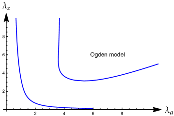
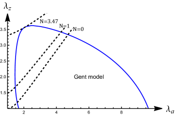
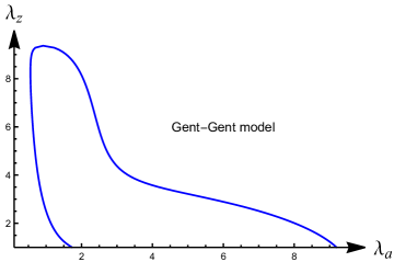
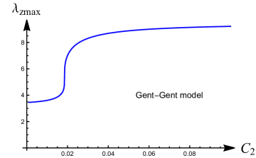
Figs 1(a, b) and 2(a) display the bifurcation condition (3.15) for the three material models given by (3.8)–(3.10). For each material model, the initiation pressure for localised bulging can be determined graphically as follows. If inflation is carried out with fixed axial force , say , then the loading path in the -plane is a curve represented by which is shown in Figs 1(b). The first (i.e. bottom left) intersection with the bifurcation curve gives the bifurcation values of and for localised bulging. In the case of fixed ends with a specified pre-stretch, the loading path is a horizontal line in the -plane and the first intersection with the bifurcation curve gives the bifurcation value of for localised bulging. In either case, the initiation pressure is computed with the use of (3.14)1. It is found that for values of and in a sufficiently small neighbourhood of and , the initiation pressures predicted by the three material models are very close to each other. For instance, in the case of fixed axial force with , the initiation pressures predicted by the Ogden, Gent, Gent-Gent models are 0.59, 0.56, and 0.61, respectively, with the predictions by the Ogden and Gent-Gent models differing by only 3.3%. However, their predictions begin to diverge for larger values of and . Most importantly, there exists the qualitative difference that whereas both the Gent and Gent-Gent models predict the existence of a maximum axial force or pre-stretch beyond which the loading path has no intersections with the bifurcation curve (and hence localised bulging becomes impossible), the Ogden model predicts otherwise due to the fact that the associated bifurcation curve extends to infinity in the direction. Also, the maximum pre-stretches predicted by the Gent and Gent-Gent models are and , respectively, which are quite different. It is then of interest to investigate whether such a pre-stretch maximum exists or not for commonly used rubber materials, and if it does, whether it is accurately predicted by the Gent and Gent-Gent material models. Since the Gent-Gent model reduces to the Gent model when , to understand the significant difference in the above predictions, we have shown in Figs 2(b) the dependence of the maximum pre-stretch on the parameter with the other two parameters and fixed at the values given by (3.11). It is seen that experiences a jump as crosses a value approximately equal to .
Motivated by the above observations, we decided to conduct additional experiments for the case of fixed ends with large pre-stretches. We used tubes made of natural latex rubber that are sold on the market as exercise bands and catheters. The tubes used all have inner radius mm, outer radius mm, and the effective experimental length is mm. The experimental set-up is the same as that described in our earlier paper, Wang et al. (2019). The measurement system mainly includes air compressor, pressure regulating valve, throttle valve, tension sensor, pressure sensor, stretching module, data acquisition card. The tension and pressure sensors are used to convert analog signal voltage output to the data acquisition card. With a volume of liters, the air compressor can provide sufficient pressure. The pressure regulating valve has a set range of MPa, and the tension sensor has a range of N. The pressure sensor has a range MPa with an accuracy of 0.25%FS. Before each experiment, the sensors were calibrated to determine the relationship between voltage, tension, and pressure. The pre-stretch is controlled by a motor screw system, and the displacement range is m. We measured the internal pressure at one end of the tube. We assume that the pressure in the tube is rapidly homogenized and so the pressure is uniform everywhere.
Before each experiment, the tube was repeatedly stretched 3 times, each time to twice the original length of the tube. The tube was subsequently installed on the experimental device, and the distance between the two fixtures was taken as the initial length . After the tube has been stretched to length so that , the two ends are fixed and inflation begins.
 |
 |
|
| (a) | (b) |
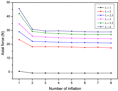
Fig. 3(a) displays the axial force required to maintain the prescribed axial pre-stretch before the start of each inflation. It shows that the above mentioned pre-stretching alone is not sufficient to remove Mullins effect. The latter only disappears after two full inflations. It can be seen that the larger the pre-stretch is, the greater the drop in the axial force is due to the first inflation. When the pre-stretch is 4, the initial tension decreases from 45.5 N to 30.8 N after the first inflation, a decrease of 32.4%. When the pre-stretch is 3.5, 3, 2.5 and 2, respectively, the corresponding reductions in the initial tension are 30.6%, 25.2%, 23.8% and 21.9%, respectively. When there is no pre-stretch , the axial tension is essentially 0 although after the first full inflation, the axial force is negative, which is due to the residual deformation of the tube caused by the inflation.
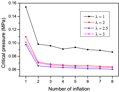
Fig. 3(b) shows that the initiation (critical) pressure for localised bulging becomes independent of the number of inflations after two full inflations, again verifying the above observation that Mullins effect can be eliminated by two full inflations (a full inflation is one in which the bulge has appeared and propagated to the ends of the tube). When the pre-stretch is , the critical pressure of the tube was reduced from 0.154 to 0.098 by 36.3% between the first two inflations, and decreased by only 2.4% from the second to the third inflations. After that, the critical pressure remained unchanged with the increase of inflation times.
 |
 |
|
| (a) | (b) |
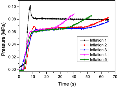
The effect of a pre-stretch in the range has been studied in Wang et al. (2019). When the pre-stretch is larger, localised bulging exhibits new characteristics. Fig. 4(a) shows the pressure variation with respect to time in five inflations of the same tube that has been subjected to a pre-stretch of . In the first inflation, localised bulging occurs when the pressure reaches 0.105 MPa. Localised bulging still occurs in the second inflation, but disappears in subsequent inflations.
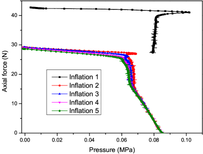
For the current case of fixed ends, the axial force keeps changing during the inflation process. Fig. 4(b) shows the relationship between the pressure and axial force when the pre-stretch is equal to . It is seen that in the first two inflations when localised bulging takes place, the axial force decreases quite slowly in uniform inflation but drops rapidly during the propagation stage. In subsequent inflations, the relationship can clearly be divided into two distinct phases. The first phase corresponds to uniform inflation in which axial force decreases quite slowly, whereas in the second phase the axial force unloads rapidly as pressure is increased, culminating in Euler buckling (for thin-walled tubes) or axisymmetric periodic buckling (for thick-walled tubes).
Table 1 shows the critical (initiation) pressure in multiple inflations with a range of pre-stretch values. The same batch of tubes were used in all experiments, but different tubes were used for different pre-stretch values. It can be seen from Table 1 that when the pre-stretch is less than 3, localised bulging occurs in all inflations. However, when the pre-stretch is , , or , respectively, localised bulging does not occur starting from the 5th, 4th and the 3rd inflation, respectively. Based on these results, we may conclude that localised bulging becomes impossible when the pre-stretch is approximately as large as 4.5. Thus, the Gent material model slightly under-predicts this value, the Gent-Gent material model over-predicts this value, whereas the Ogden material model cannot predict this behaviour. Interestingly, in contrast with the observation made by Hejazi et al. (2021) that rupture occurs when the pre-stretch is equal to or larger than 3, we have not observed rupture before the bulge (if it occurs) has propagated to the tube ends. The only explanation that we may offer is that the particular latex rubber tubes that we used are less prone to rupture.
| 1 | 2 | 2.5 | 3 | 3.5 | 4 | 4.5 | |
|---|---|---|---|---|---|---|---|
| inflation 1 | 0.1542 | 0.1094 | 0.0975 | 0.1014 | 0.1005 | 0.1128 | 0.136 |
| inflation 2 | 0.0983 | 0.0713 | 0.0656 | 0.07 | 0.0732 | 0.075 | 0.0825 |
| inflation 3 | 0.0959 | 0.0684 | 0.0641 | 0.0668 | 0.0695 | 0.0681 | x |
| inflation 4 | 0.0909 | 0.067 | 0.0631 | 0.0656 | 0.0662 | x | x |
| inflation 5 | 0.0936 | 0.066 | 0.0625 | 0.0645 | x | x | x |
| inflation 6 | 0.0901 | 0.066 | 0.0613 | 0.0637 | x | x | x |
| inflation 7 | 0.089 | 0.065 | 0.0613 | 0.0633 | x | x | x |
| inflation 8 | 0.0864 | 0.064 | 0.0605 | 0.0632 | x | x | x |
4 Characterisation of the propagation stage
Having established the fact that the Gent material model can qualitatively predict the existence of a limiting pre-stretch better than the Gent-Gent model or the Ogden model, we now characterise the propagation stage using the Gent material model.
 |
 |
|
| (a) | (b) |
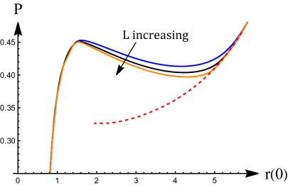
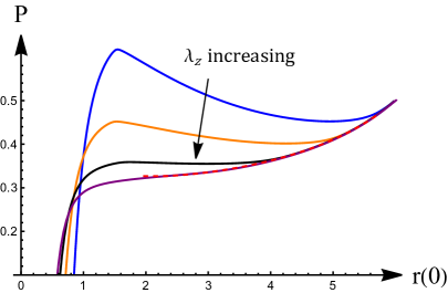
It was reported in Wang et al. (2019) that in the case of fixed ends, the pressure would increase to a maximum under uniform inflation, reach a minimum after the initiation of a bulge, and then increase monotonically. The latter ascending branch was not described analytically. In view of the results reported in Figure 13 of Fu et al. (2021) for an analogous problem, see also Henann & Bertoldi (2014) and Xuan & Biggins (2017), we anticipate that the right ascending branch mentioned above should approach a single asymptote that is independent of the pre-stretch or the tube length. This is verified in Fig. 5 where we present our Abaqus simulation results for a variety of pre-stretch values and tube lengths. Such an asymptote does indeed exist, as shown in Fig. 5 in dashed line. This asymptote is determined as follows.
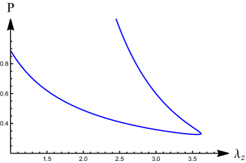
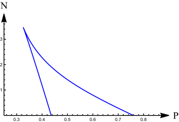
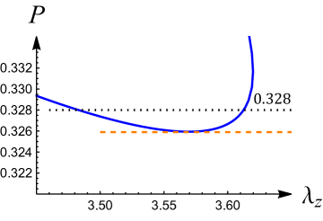
We refer to Fig. 1(b) and note that there exists a single loading curve in the case of fixed axial force, approximately given by , that is tangent to the bifurcation curve. Localised bulging becomes impossible if . In a similar way, in the case of fixed ends, the horizontal line is tangent to the bifurcation curve, and localised bulging becomes impossible if . These facts are made more transparent in Fig. 6(a, b) where the bifurcation curve is presented in the -plane and -plane, respectively. The curve in Fig. 6(a) is obtained by expressing as a function of through the bifurcation condition, and then plot against . The curve in Fig. 6(b) is obtained using parametric plotting by viewing and as functions of , with determined by the bifurcation condition. The maximum of in Fig. 6(b) is given by . This figure also provides the additional information that localised bulging is impossible under axial tension if is less than , the minimum value of in Fig. 6(a) attained at . This minimum also features in the force versus diagrams to be discussed next.
 |
 |
|
| (a) | (b) |
 |
 |
|
 |
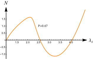 |
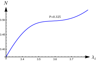
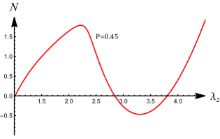
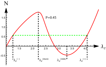
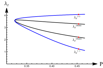
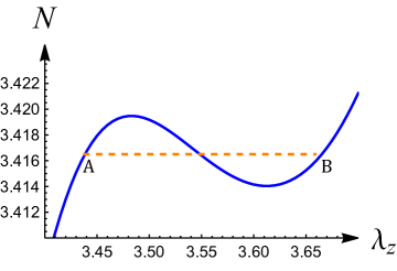
To appreciate why localised bulging becomes impossible when is less than and why Abaqus simulations usually abort when reaches a large enough value, we now investigate the dependence of on as is increased gradually. A typical set of results is presented in Fig. 7. It is seen that when is sufficiently small, the versus curve is monotonically increasing. It is only when becomes larger than the above-mentioned minimum that the variation of has an shape with a maximum followed by a minimum. This is consistent with the result that when inflation is carried out with fixed and variable , localised bulging takes place when ; see Eqn (21) in Fu & Ilíchev (2015). For instance, when , the maximum of occurs at (with the corresponding equal to ). This means that (i) when the tube is stretched with pressure fixed at , localised bulging will occur when reaches , and also (ii) when the tube is inflated with a pre-stretch , localised bulging will occur when . When the variation of has an shape, equal area rule may be applied and a Maxwell state may be obtained. Fig. 8(b) shows the variation of the two values of corresponding to the Maxwell state, together with the two values of corresponding to the maximum and minimum of . The notations , , , are defined in Fig. 8(a) where we show the variation of against for a typical . For each , Fig. 8(b) gives the two Maxwell values and . The corresponding values of , say , , can then be determined by solving (3.14)1. The larger of these two values is the appearing in Fig. 5, and the collection of computed in this way forms the asymptote in Fig. 5.
It is seen in Fig. 7(d) that when becomes as large as , the axial force corresponding to the Maxwell state is negative. When is negative or sufficiently negative depending on the wall thickness, Euler buckling or axisymmetric buckling would occur, and Abaqus simulations would eventually abort. Thus, the asymptote in Fig. 5 starts at the minimum and terminates at a value approximately equal to at which .
It is also seen in Fig. 5(b) that the asymptote, where it exists, coincides with the solid curve corresponding to the special stretch . This is the stretch at which attains its minimum, as mentioned earlier. This special stretch is discussed in the next section.
 |
 |
|
| (a) | (b) |
 |
 |
|
| (a) | (b) |
5 Solution near the pressure minimum
Fig. 9 shows a close-up of the bifurcation curve in Fig. 6(a) near the pressure minimum where and . We consider the scenario whereby the tube is first subjected to an axial pre-stretch given by , and then inflated by increasing gradually. It is anticipated that when reaches the critical value , a bifurcation will take place and an inhomogeneous deformation with non-constant and will emerge. We denote the values of and near the end by and , respectively. For a tube that is sufficiently long, these values are effectively the same values as (the difference being exponentially small). In other words, as far as localised bulging or a kink solution is concerned, the tube is effectively infinite provided it is sufficiently long.
The inflation pressure corresponding to the Gent model is given by
| (5.16) |
This equation can be solved explicitly to express in terms of and , and the solution is denoted by in the subsequent analysis.
With and specified, we look for an inhomogeneous bifurcated solution that approaches this uniform state as the end is approached. Extending the analysis of Fu et al. (2008), we find that if , then the incremental solution satisfies the ordinary differential equation
| (5.17) |
where the three coefficients have long but explicit expressions which are not written out here for the sake of brevity. The bifurcation condition corresponds to (Fu et al., 2008) and the pressure minimum in Fig. 9 corresponds to . With expressed in terms of and with the use of (5.16), we rewrite equation (5.17) symbolically in the form
| (5.18) |
where, for instance, . With fixed, the pressure is taken to be the bifurcation parameter.
Denote the coordinates of the pressure minimum in Fig. 9(a) by . When so that , an explicit expression for the localised solution may be obtained from (5.18) by neglecting the quartic and higher order terms on the right hand side. It can then be deduced that the localised solution is of the bulging type if (corresponding to ), and is of the necking type if . This switching from the bulging type to the necking type was also observed by Ye et al. (2020) through a weakly nonlinear analysis for a tube of arbitrary thickness. Here we focus on the special case with .
We note, however, that despite the assumption that uniform inflation is now carried out with , as soon as is increased beyond its minimum, a bifurcation from the homogeneous state into an inhomogeneous state takes place and the will change in order to satisfy the condition that the total length is fixed at . Thus, we set
| (5.19) |
where is a small positive parameter, and and are constants. On substituting these expansions into the solution of (5.16), we obtain
| (5.20) |
where .
Expanding the right hand side of (5.18) in terms of , we obtain
| (5.21) |
where , , , , all partial derivatives being evaluated at the pressure minimum. In obtaining (5.21) we have made use of the property that at the pressure minimum. This property also explains the scaling in (5.19)2.
It can be seen that the first four terms on the right hand side of (5.21) are all of the same order as the left hand side if and varies on a long spatial scale of order . In terms of the scaled variables
| (5.22) |
the amplitude equation (5.21) reduces to
| (5.23) |
after we have neglected terms of order or higher, where and are the two roots of
We consider the special case when these two roots are repeated, which occurs when
| (5.24) |
and the roots are
| (5.25) |
In this case, equation (5.23) reduces to , where we have assumed, without loss of generality, that so that the solution decays to the constant state as the end is approached. This differential equation can be integrated to yield the explicit kink-wave solution (Giudici & Biggins, 2020; Fu et al., 2021)
| (5.26) |
where the constant of integration has been chosen such that .
For the Gent material model under consideration, we find that
| (5.27) |
To conform with the assumption , we require so that we take the minus choice in (5.24) for . As a result, as , we have and , respectively. Thus, the non-trivial solution represents a “two-phase” deformation (or a kink-wave solution) with the “two-phases” given by
or more precisely,
| (5.28) |
The corresponding values of are
| (5.29) |
where the ratio is given just below (5.20).
As a consistency check, we note that the two values of given by (5.29) should correspond to the coordinates of points and in Fig. 9(b) where the dashed line cuts the curve into equal areas. For values of and close to and , respectively, the has the Taylor expansion
| (5.30) |
where
with all the partial derivatives evaluated at the pressure minimum. It then follows that to leading order the dashed line in Fig. 9(b) is given by
| (5.31) |
and the points and have coordinates
| (5.32) |
Consistency between this result and (5.29) requires that
| (5.33) |
We have verified numerically that these relations are indeed satisfied.
Combining the simulation results in Fig. 5(b), the theoretical results in Fig. 8(b), and the analysis in this section so far, we may now summarise the evolution of the deformation in an inflated tube with fixed ends as follows. If inflation is carried out with a pre-stretch , then increasing with the fixed follows a horizontal line in Fig. 8(b). When this line intersects the curve marked “”, a localised bulge will initiate. If inflation is carried out with mass control, the pressure will decrease to a minimum and then rise again, as shown in Fig. 5(b). However, if it is under pressure control (so that pressure is not allowed to decrease), a snap-through will take place and the deformation will jump to a “two-phase” deformation with the values of in the two “phases” given by and , respectively; the latter two values can be read off from Fig. 8(b) by drawing a vertical line at the pressure assigned. If the pressure is increased further after the snap-through, the values of and in the two “phases” will change continuously by staying on the same branches in Fig. 8(b). On the other hand, if inflation is carried out with , the behaviour is similar except that the localisation is of the necking type and the intersection is with the curve marked “” in Fig. 8(b). In the exceptional case when inflation is carried out with exactly, the bifurcation is exceptionally supercritical: when reaches the minimum in Fig. 8(b), the deformation smoothly evolves into a “two-phase” deformation without going through a snap-through, as can be seen in Fig. 5(b). This two “phase” deformation is described analytically by (5.26) when is only slightly larger than its minimum. Further away from this minimum, the values of and in the two “phases” are given by the same branches in Fig. 8(b) although an analytical expression for the narrow transition region no longer exists. The proportion of each “phase” is determined such that the total length of the tube remains at .
6 Conclusion
The current study was motivated by two considerations. Firstly, it is observed that the Ogden material model and the Gent or Gent-Gent material model make similar and realistic predictions for localised bulging when the axial pre-strain (pre-stretch minus unity) or the fixed axial force is sufficiently small, but their predictions diverge for large values of axial pre-strain or tension. It is then of interest to investigate how an actual rubber tube would behave under large pre-strains. Secondly, the entire inflation process for the case of fixed axial force is well understood both theoretically and experimentally, but this does not seem to be the case when the ends of the tube are fixed during inflation. Previous experiments have shown that after the initiation of a localised bulge the pressure would reach a minimum and then rise again, but this ascending branch has not previously been described analytically.
We carried out experiments using a typical commercially available rubber tube and confirmed that there does indeed exist a maximum pre-stretch above which localised bulging will not occur under inflation. The Gent material model can describe this property both qualitatively and quantitatively. This is probably because the existence of the maximum pre-stretch for localised bulging is closely related to the finite chain extensibility that the Gent model was designed to model. The Gent-Gent model can predict this property qualitatively. It is also possible to predict this property quantitatively by re-calibrating the Gent-Gent model and requiring to be sufficiently small in fitting the model to experimental data, guided by the results in Fig. 2(b), but we did not pursue this possibility further. We cannot, however, conclude that this property is shared by all other rubber or rubber-like materials. Thus, the current study only serves to show that finding a tractable material model that can serve all purposes is extremely challenging, if not impossible.
Our analysis of the above-mentioned ascending branch has been inspired by the recent study on the localised bulging/necking of a solid cylinder under surface tension (Fu et al., 2021), which in turn has benefitted from previous studies on the problem of localised bulging in an inflated rubber tube without surface tension. In view of what has been achieved in the latter paper, we anticipated that the ascending branch should tend to an asymptote that is independent of the tube length or the pre-stretch. This was verified by both analysis and Abaqus simulations in the current study.
It is previously known that localised bulging is also possible when the tube is extended/stretched at a fixed pressure, and it occurs when the tension reaches the maximum corresponding to uniform extension. By presenting the bifurcation condition in the -plane, it is revealed that there exists a minimum pressure below which localized bulging would be impossible if the tube were to be continuously stretched axially. This minimum pressure is attained at when the Gent material model is used. The latter stretch value is very close to the stretch maximum above which localised bulging becomes impossible when the tube is inflated by an internal pressure. For inflation with fixed ends and a pre-stretched , the first bifurcation corresponds to localized bulging if and localised necking if , and the bifurcation is sub-critical in both cases. In the exceptional case when inflation is carried out with , the tube will deform smoothly into a “two-phase” state when the pressure is increased across the critical value predicted by the bifurcation condition, and the bifurcation is exceptionally super-critical.
Acknowledgements
This work was supported by the National Natural Science Foundation of China (Grant Nos 12072224, 12002067). The Abaqus simulations were carried out on TianHe-1 (A) at the National Supercomputer Center in Tianjin, China.
References
- Alexander (1971) Alexander, H. (1971). Tensile instability of initially spherical balloons. Int. J. Eng. Sci., 9, 151–160.
- Alhayani et al. (2013) Alhayani, A. A., Giraldo, J. A., Rodríguez1, J., & Merodio, J. (2013). Computational modelling of bulging of inflated cylindrical shells applicable to aneurysm formation and propagation in arterial wall tissue. Finite Elem. Anal. Des., 73, 20–29.
- Alhayani et al. (2014) Alhayani, A. A., Rodríguez, J., & Merodio, J. (2014). Competition between radial expansion and axial propagation in bulging of inflated cylinders with application to aneurysms propagation in arterial wall tissue. Int. J. Eng. Sci., 85, 74–89.
- Bucchi & Hearn (2013a) Bucchi, A., & Hearn, G. (2013a). Predictions of aneurysm formation in distensible tubes: Part A – theoretical background to alternative approaches. Int. J. Mech. Sci., 71, 1–20.
- Bucchi & Hearn (2013b) Bucchi, A., & Hearn, G. (2013b). Predictions of aneurysm formation in distensible tubes: Part B – theoretical background to alternative approaches. Int. J. Mech. Sci., 70, 155–170.
- Chater & Hutchinson (1984) Chater, E., & Hutchinson, J. W. (1984). On the propagation of bulges and buckles. ASME J. Appl. Mech., 51, 269–277.
- Chen (1997) Chen, Y.-C. (1997). Stability and bifurcation of finite deformations of elastic cylindrical membranes - Part I. stability analysis. Int. J. Solids Struct., 34, 1735–1749.
- Dehghani et al. (2019) Dehghani, H., Desena-Galarza, D., Jha, N. K., Reinoso, J., & Merodio, J. (2019). Bifurcation and post-bifurcation of an inflated and extended residually-stressed circular cylindrical tube with application to aneurysms initiation and propagation in arterial wall tissue. Finite Elem. Anal. Des., 161, 51–60.
- Demirkoparan & Merodio (2017) Demirkoparan, H., & Merodio, J. (2017). Bulging bifurcation of inflated circular cylinders of doubly fiber-reinforced hyperelastic material under axial loading and swelling. Math. Mech. Solids, 22, 666–682.
- Emery & Fu (2021a) Emery, D., & Fu, Y. B. (2021a). Elasto-capillary circumferential buckling of soft tubes under axial loading: existence and competition with localised beading and periodic axialmodes. Mech. Soft Mater., 3, Article 3.
- Emery & Fu (2021b) Emery, D., & Fu, Y. B. (2021b). Localised bifurcation in soft cylindrical tubes under axial stretching and surface tension. Int. J. Solids Struct., 219-220, 23–33.
- Emery & Fu (2021c) Emery, D., & Fu, Y. B. (2021c). Post-bifurcation behaviour of elasto-capillary necking and bulging in soft tubes. Proc. R. Soc. A, 477, 20210311.
- Fu & Ilíchev (2015) Fu, Y. B., & Ilíchev, A. T. (2015). Localized standing waves in a hyperelastic membrane tube and their stabilization by a mean flow. Math. Mech. Solids, 20, 1198–1214.
- Fu et al. (2021) Fu, Y. B., Jin, L. S., & Goriely, A. (2021). Necking, beading, and bulging in soft elastic cylinders. J. Mech. Phys. Solids, 147, 104250.
- Fu et al. (2016) Fu, Y. B., Liu, J. L., & Francisco, G. S. (2016). Localized bulging in an inflated cylindrical tube of arbitrary thickness – the effect of bending stiffness. J. Mech. Phys. Solids, 90, 45–60.
- Fu et al. (2008) Fu, Y. B., Pearce, S. P., & Liu, K.-K. (2008). Weakly nonlinear analysis of localized bulging of an inflated hyperelastic tube of arbitrary wall thickness. Int. J. Non-linear Mech., 43, 697–706.
- Fu et al. (2012) Fu, Y. B., Rogerson, G. A., & Zhang, Y. T. (2012). Initiation of aneurysms as a mechanical bifurcation phenomenon. Int. J. Non-linear Mech., 47, 179–184.
- Gent (1996) Gent, A. (1996). A new constitutive relation for rubber. Rubber Chem. Technol., 69, 59–61.
- Gent & Rivlin (1952) Gent, A. N., & Rivlin, R. S. (1952). Experiments on the mechanics of rubber ii: The torsion, inflation and extension of a tube. Proc. Roy. Soc. B, 65, 118–121.
- Giudici & Biggins (2020) Giudici, A., & Biggins, J. S. (2020). Ballooning, bulging and necking: an exact solution for longitudinal phase separation in elastic systems near a critical point. Phy. Rev. E, 102, 033007.
- Goncalves et al. (2008) Goncalves, P. B., Pamplona, D. C., & Lopes, S. R. X. (2008). Finite deformations of an initially stressed cylindrical shell under internal pressure. Int. J. Mech. Sci., 50, 92–103.
- Haughton & Ogden (1979a) Haughton, D. M., & Ogden, R. W. (1979a). Bifurcation of inflated circular cylinders of elastic material under axial loading i. membrane theory for thin-walled tubes. J. Mech. Phy. Solids, 27, 179–212.
- Haughton & Ogden (1979b) Haughton, D. M., & Ogden, R. W. (1979b). Bifurcation of inflated circular cylinders of elastic material under axial loading ii. exact theory for thick-walled tubes. J. Mech. Phy. Solids, 27, 489–512.
- Hejazi et al. (2021) Hejazi, M., Hsiang, Y., & Phani, A. S. (2021). Fate of a bulge in an inflated hyperelastic tube: theory and experiment. Proc. Roy. Soc. A, 477, 20200837.
- Henann & Bertoldi (2014) Henann, D. L., & Bertoldi, K. (2014). Modeling of elasto-capillary phenomena. Soft Matter, 10, 709–717.
- Horny et al. (2015) Horny, L., Netusil, M., & Horak, Z. (2015). Limit point instability in pressurization of anisotropic finitely extensible hyperelastic thin-walled tube. Int. J. Non-linear Mech., 77, 107–114.
- Jin et al. (2021) Jin, L. S., Forte, A. E., & K, B. (2021). Mechanical valves for on-board flow control of inflatable robots. Adv. Sci., 5, DOI: 10.1002/advs.202101941.
- Kanner & Horgan (2007) Kanner, L. M., & Horgan, C. O. (2007). Elastic instabilities for strain-stiffening rubber-like spherical and cylindrical thin shells under inflation. Int. J. Non-linear Mech., 42, 204–215.
- Kyriakides & Chang (1990) Kyriakides, S., & Chang, Y.-C. (1990). On the inflation of a long elastic tube in the presence of axial load. Int. J. Solids Struct., 26, 975–991.
- Kyriakides & Chang (1991) Kyriakides, S., & Chang, Y.-C. (1991). The initiation and propagation of a localized instability in an inflated elastic tube. Int. J. Solids Struct., 27, 1085–1111.
- Lestringant & Audoly (2018) Lestringant, C., & Audoly, B. (2018). A diffuse interface model for the analysis of propagating bulges in cylindrical balloons. Proc. Roy. Soc. A, 474, 20180333.
- Lestringant & Audoly (2020) Lestringant, C., & Audoly, B. (2020). Asymptotically exact strain-gradient models for nonlinear slender elastic structures: a systematic derivation method. J. Mech. Phys. Solids, 136, 103730.
- Liu et al. (2019) Liu, Y., Ye, Y., Althobaiti, A., & Xie, Y. X. (2019). Prevention of localized bulging in an inflated bilayer tube. Int. J. Mech. Sci., 153, 359–368.
- Lu et al. (2015) Lu, T. Q., An, L., Li, J. G., Yuan, C., & Wang, T. J. (2015). Electro-mechanical coupling bifurcation and bulging propagation in a cylindrical dielectric elastomer tube. J. Mech. Phy. Solids, 85, 160–175.
- Mallock (1891) Mallock, A. (1891). Note on the instability of india-rubber tubes and balloons when distended by fluid pressure. Proc. Roy. Soc., A 49, 458–463.
- Ogden (1972) Ogden, R. W. (1972). Large deformation isotropic elasticity – on the correlation of theory and experiment for incompressible rubberlike solids. Proc. Roy. Soc., A 326, 565–584.
- Ogden et al. (2004) Ogden, R. W., Saccomandi, G., & Sgura, I. (2004). Fitting hyperelastic models to experimental data. Comput Mech, 34, 484–502.
- Pamplona et al. (2006) Pamplona, D. C., Goncalves, P. B., & Lopes, S. R. X. (2006). Finite deformations of cylindrical membrane under internal pressure. Int. J. Mech. Sci., 48, 683–696.
- Pucci & Saccomandi (2002) Pucci, E., & Saccomandi, G. (2002). A note on the gent model for rubber-like materials. Rubber Chem Technol, 75, 839–852.
- Ren et al. (2011) Ren, J. S., Zou, J. W., & Yuan, X. G. (2011). Instability analysis in pressurized three-layered fiber-reinforced anisotropic rubber tubes in torsion. Int. J. Eng. Sci., 49, 342–353.
- Rivlin (1949) Rivlin, R. S. (1949). Large elastic deformations of isotropic materials. vi. further results in the theory of torsion, shear and flexture. Phil. Trans. Roy. Soc. Lond. A, 242, 173–195.
- Rodríguez-Martínez et al. (2015) Rodríguez-Martínez, J. A., Fernández-Sáez, J., & Zaera, R. (2015). The role of constitutive relation in the stability of hyper-elasticspherical membranes subjected to dynamic inflation. Int. J. Eng. Sci., 93, 31–45.
- Shi & Moita (1996) Shi, J., & Moita, G. F. (1996). The post-critical analysis of axisymmetric hyper-elastic membranes by the finite element method. Comput. Methods Appl. Mech. Engrg, 135, 265–281.
- Shield (1972) Shield, R. T. (1972). On the stability of finitely deformed elastic membranes. Part II: Stability of inflated cylindrical and spherical membranes. ZAMP, 23, 16–34.
- Takla (2018) Takla, M. (2018). Bifurcation of elastic-plastic thick-walled cylindrical structures. Int. J. Mech. Sci., 141, 303–315.
- Usevitch et al. (2020) Usevitch, N. S., Hammond, Z. M., Schwager, M., Okamura, A. M., Hawkes, E. W., & Follmer, S. (2020). An untethered isoperimetric soft robot. Sci. Robot., 5, DOI: 10.1126/scirobotics.aaz0492.
- Varatharajan & DasGupta (2017) Varatharajan, N., & DasGupta, A. (2017). Study of bifurcation in a pressurized hyperelastic membrane tube enclosed by a soft substrate. Int. J. Non-linear Mech., 95, 233–241.
- Wang et al. (2017) Wang, J., Althobaiti, A., & Fu, Y. B. (2017). Localized bulging of rotating elastic cylinders and tubes. J. Mech. Mater. Struct., 12, 545–561.
- Wang & Fu (2018) Wang, J., & Fu, Y. B. (2018). Effect of double-fibre reinforcement on localized bulging of an inflated cylindrical tube of arbitrary thickness. J. Eng. Math., 109, 21–30.
- Wang & Fu (2021) Wang, M., & Fu, Y. B. (2021). Necking of a hyperelastic solid cylinder under axial stretching: Evaluation of the infinite-length approximation. Int. J. Eng. Sci., 159, 103432.
- Wang et al. (2019) Wang, S. B., Guo, Z. M., Zhou, L., Li, L. A., & Fu, Y. B. (2019). An experimental study of localized bulging in inflated cylindrical tubes guided by newly emerged analytical results. J. Mech. Phy. Solids, 124, 536–554.
- Wineman (2015) Wineman, A. S. (2015). Determining the time of bulge formation in an elastomeric tube as it inflates, elongates and alters chemorheologically. Math. Mech. Solids, 20, 9–24.
- Wineman (2017) Wineman, A. S. (2017). Bulge initiation in tubes of time-dependent materials. Math. Mech. Solids, 22, 636–648.
- Xuan & Biggins (2017) Xuan, C., & Biggins, J. (2017). Plateau-rayleigh instability in solids is a simple phase separation. Phy. Rev. E, 95, 053106.
- Ye et al. (2019) Ye, Y., Liu, Y., Althobaiti, A., & Xie, Y. X. (2019). Localized bulging in an inflated bilayer tube of arbitrary thickness: Effects of the stiffness ratio and constitutive model. Int. J. Mech. Sci., 176, 173–184.
- Ye et al. (2020) Ye, Y., Liu, Y., & Fu, Y. B. (2020). Post-bifurcation analysis of a thin-walled hyperelastic tube under inflation. J. Mech. Phys. Solids, 135, 103804.
- Yin (1977) Yin, W.-L. (1977). Non-uniform inflation of a cylindrical elastic membrane and direct determination of the strain energy function. J. Elast., 7, 265–282.
- Yu & Fu (2021) Yu, X., & Fu, Y. B. (2021). An analytic derivation of the bifurcation conditions for localization in hyperelastic tubes and sheets. ZAMP, submitted.
- Zhou et al. (2018) Zhou, L., Wang, S. B., Li, L. A., & Fu, Y. B. (2018). An evaluation of the gent and gent-gent material models using inflation of a plane membrane. Int. J. Mech. Sci., 146-147, 39–48.