Coupling between improper ferroelectricity and ferrimagnetism in hexagonal ferrites
Abstract
Antisymmetric Dzyaloshinskii-Moriya (DM) interactions generating from the spin-orbit coupling induce various fascinating properties, like magnetoelectric (ME) effect, weak ferromagnetism and non-trivial topological spin textures like skyrmions, in real materials. Compared to their symmetric isotropic exchange counterpart, these interactions are generally of a weaker order of strength, creating modest twisting in the spin structure which results in weak ferromagntism or weak linear ME effect. Our proposed two-sublattice model, in contrast, predicts a hitherto unobserved, charge ordered non-collinear ferrimagnetic behavior with a considerably high magnetization M coexisting with a ferroelectric (FE) order with an electric polarization P and a strong cross coupling between them which is primarily driven by the inter-sublattice DM interactions. The key to realize these effects is the coupling between these microscopic interactions and the FE primary order parameter. We predict microscopic mechanisms to achieve electric field E induced spin-reorientation transitions and 180∘ switching of the direction of M. This model was realized in the hexagonal phase of LuFeO3 doped with electrons. This system shows 15 C/cm2, 1.3 /Fe and magnetic transition near room temperature ( 290 K). Our theoretical results are expected to stimulate further quest for energy-efficient routes to control magnetism for spintronics applications.
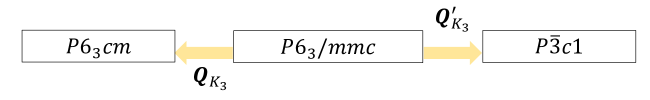
Multisublattice magnets show various fascinating properties, like spin-reorientation (SR) transitions RFO-MAG ; ref2 ; yamaguchi ; tokura ; Rao ; Tokunaga ; Zhao ; DAS , non-trivial ferrimagnetism and topological order (FIM1, ; FIM2, ; FIM3, ; FIM4, ; FIM5, ; FIM6, ; FIM7, ; FIM8, ; FIM9, ), which owe their origin to various microscopic interactions. Moreover, the quest for efficient routes of manipulation of these microscopic interactions by the application of external stimuli in order to control the properties of these systems, is at the forefront of various research activities FIM9 ; FIM10 ; FIM11 ; FIM12 ; FIM13 ; FIM14 . LuFe2O4 is one such system, exhibiting Fe2+/Fe3+ charge ordered (CO) pattern in the Fe double layer, resulting in ferrimagnetic order with a robust magnetization 0.8 - 1.4 /Fe LFO124-MAG1 below 240 K (LFO124-1, ; LFO124-2, ) and to the genesis of various interesting functionalities (LFO124-F1, ; LFO124-F2, ; LFO124-F3, ; LFO124-F4, ), though its ferroelectric (FE) order remains ambiguous LFO124-1 ; LFO124-2 ; LFO124-3 ; LFO-AFE1 ; LFO-AFE2 ; LFO-AFE3 ; LFO-AFE4 ; LFO-JM1 . The constructed (LuFeO3)m/(LuFe2O4)1 superlattices manifest various interesting properties (LFO-JM1, ; LFO-JM, ; LFO-JM2, ), like room temperature multiferroic and magnetoelectric (ME) behavior and dimensionality controlled topological order. Hexagonal LuFeO3 shows improper FE behavior with an electric polarization (P) below 1040 K and canted antiferromagnetic (AFM) behavior below 147 K with a net magnetization of 0.03 /Fe (LFO113-1, ; LFO113-HD, ; LFO113-2, ; LFO113-3, ; LFO113-4, ). The ferrimagnetic magnetization ( M ) in LuFe2O4 arises due the CO pattern () characterized by the wave vector , while in LuFeO3 P gets induced by an zone boundary structural distortion ( ) following symmetry at of the paraelectric (PE) structure (LFO-FE1, ; LFO-FE2, ; LFO-FE3, ). The engineered superlattices not only exhibit enhancement in the magnetic transition temperature and magnetization compared to the parent systems, but are also reported to show strong ME switching phenomena LFO-JM1 . However, the cross-coupling between ferrimagnetism and ferroelectricity is not well understood yet.
Here, employing first-principles density functional theory (DFT) calculations and finite temperature Monte Carlo (MC) simulations, we propose an alternate model where such C-type CO pattern forms in the LuFeO3 structure itself, under electron doping. We observed that the doped system retains its improper FE nature, with an electric polarization P at par with the parent system. The C-type pattern creates a two-sublattice model where the Fe2+ triangular lattice is embedded within the Fe3+ hexagonal lattice, resulting in the formation of unique non-collinear ferrimagnetic phases with the spins in the two magnetic sublattices aligned in mutually perpendicular () directions, giving rise to a high magnetization M. As in ferrite superlattices, the order of magnitude of M and the corresponding magnetic transition temperature, both show significant enhancement in comparison to the parent material. These phases originate primarily due to the interplay between inter-sublattice Dzyaloshinskii-Moriya (DM) interactions and , predicting microscopic mechanisms to achieve electric field induced SR transitions and 180∘ ME switching, where P and M simultaneously switch their individual orientations.
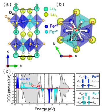
In LuFeO3, the FE order is improper as the P is the secondary effect of a primary distortion, . The distortion, which breaks the inversion symmetry of , assumes the form of tilted FeO5 bipyramids towards (away) the axis and results in one-up/two-down (one-down/two-up) buckling of the Lu ions LFO113-HD . is defined by its magnitude and a phase factor representing the direction of the tilt of FeO5 bipyramids. The non-linear coupling between and induces electric polarization P directed along the crystallographic c () axis, following the Landau free energy LFO113-HD ; LFO-FE3 ,
| (1) |
where takes up six discrete values () due to symmetry, where P of the odd and even number structures are oriented in mutually opposite directions LFO-NS . This leads to the formation of topologically protected FE and ME vortex domain structures in rare-earth manganites and ferrites (TPD-1, ; TPD-2, ; TPD-3, ; TPD-YU, ; TPD-4, ; TPD-5, ; TPD-6, ; LFO-JM2, ). Notably also transforms as symmetry (see Sec. II in Supplementary Materials SM ). GGA+ results (Sec. I in the Supplementary Materials (SM, )) considering 4.5 eV and 0.95 eV at the Fe sites (LFO-JM1, ; LFO-JM, ; LFO113-HD, ), show that LuFeO3 crystallizes in the FE phase with 24 meV/f.u. lower in energy compared to structure. It exhibits 14 C/cm2 which agrees with the previous reports LFO113-HD .
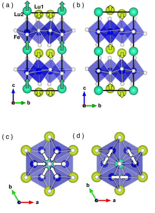
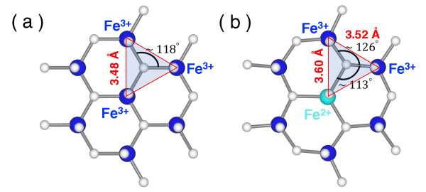
We indroduced excess carriers in the system by changing the number of valence electrons and adding a homogeneous background charge to keep the system neutral, like in previous studies e-FE1 ; e-FE2 . Optimizing both doped and structures, we observed that, LuFeO3 at the electrons () per Fe doping level clearly shows the formation two distinct type of Fe ions (see Fig. 1). Where of them show completely filled majority spin channels leaving the minority channels almost empty and hence a 3+ nominal oxidation state (3 configuration), similar to LuFeO3 LFO113-HD . Whereas of them show partial occupancy in the minority spin channels (with 3 electronic configuration resulting in 2+ oxidation state) in addition to completely filled majority spin channels. A -type CO structure with each Fe layer consisting of Fe2+ triangular lattice embedded within Fe3+ hexagonal lattice (Fig. 1(a) and (b)) is formed, as was observed in LuFe2O4. The doped system exhibits distortion characterized by an electric polarization 15 C/cm2 and insulating behavior with 0.8 eV band gap, similar to parent LuFeO3. The mixed valent state was 180 meV/f.u. higher in energy (see Sec. II in the Supplementary Materials SM for details).
To determine the resulting magnetic order of the CO two-sublattice system, we conducted MC simulations considering spin Hamiltonian with the general form,
| (2) |
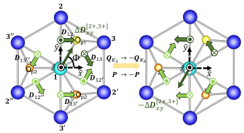
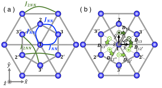
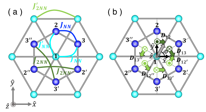
here and represent the Fe-Fe symmetric exchange (SE) and antisymmetric (DM) interactions, respectively. denotes single ion anisotropy (SIA) tensor of the Fe ions. We constructed two models, and , corresponding to the undoped (one-sublattice ) and doped (two-sublattice) systems, respectively (detail description of these models and subsequent MC simulations are given in Sec. III of the Supplementary Materials SM ). and consist of, ( i ) nearest-neighbor (NN), second-nearest-neighbor (2NN) in-plane and effective inter-layer Fe-Fe SE interactions. ( ii ) NN Fe-Fe DM interactions as depicted in Fig. 2. The transverse component is induced by the distortion , while the longitudinal component is already existing in the PE phase. The DM vectors in the consecutive Fe layers are anti-parallel to each other due to symmetry. (iii) The SIA has and non-zero off-diagonal components .
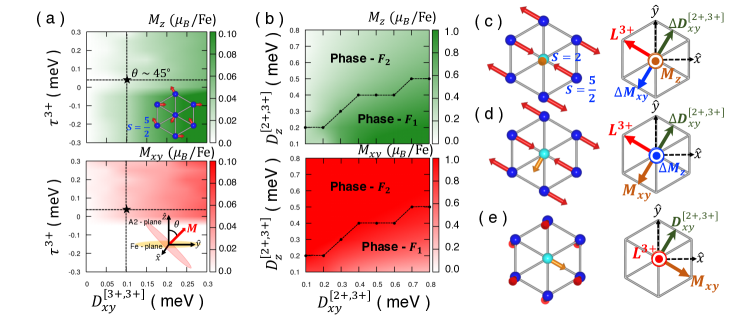
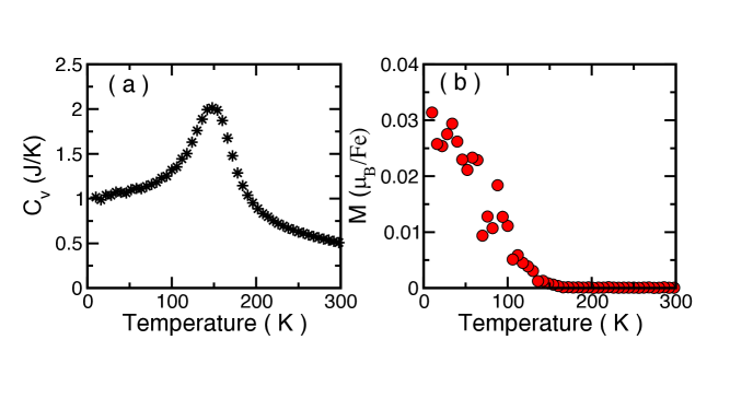
Fig. 3(a) shows the results of MC simulations employing model . The estimated values of DM interactions and SIA parameters (Sec.III-B in the supplementary Materials (SM, )) show that, i.e. (Fig. 2) and . We incorporated these postulates in MC simulations. Both NN and 2NN interactions are AFM in nature with estimated strengths of 6.3 meV and 0.3 meV, respectively, agreeing well with the previous reports (LFO113-HD, ). Geometric frustration created by the six NN AFM Fe-Fe SE interactions in the triangular lattice induces the formation of multiple, energetically degenerate, 120∘ non-collinear orders (LFO113-HD, ). The effective AFM 0.4 meV interaction breaks the geometric frustration and stabilizes the A2-type magnetic order () (Fig. 3(a)). Notably, Fe3+ ions result in uniaxial () magnetic anisotropy, contrasting the in-plane () magnetic anisotropy of Mn3+ ions in its manganite counterpart LFO113-HD , which tilts the A2 spin ordered plane (Fig. 3(a)). gives rise to a modest canted magnetization. DFT estimated values of magnetic parameters stabilize 45∘ tilted A2 phase below 148 K exhibiting a canted magnetization of 0.03 /Fe (Fig.S5 and S6 in the Supplementary Materials SM ). These observations are at par with experimental reports LFO113-1 ; LFO113-HD ; LFO113-2 ; LFO113-3 ; LFO113-4 , establishing the power of this approach.
Fig. 3(b) shows results of MC simulations employing model . The key modifications of compared to are, (1) the strength of the NN Fe3+-Fe3+ interaction is increased from 6.3 8.5 meV (primarily due to the enhancement of the Fe3+-O-Fe3+ of the mediating path (Fig. S8 in Supplementary Materials SM ). (2) The NN AFM Fe2+-Fe3+ interaction 1.1 meV is introduced. (3) A weak FM 2NN Fe2+-Fe2+ interaction -0.1 meV is incorporated. (4) Fe2+ ions exhibit strong spin-orbit (LS) coupling with orbital moment 0.2 , order of magnitude stronger than Fe3+ ion ( 0.1). As in LuFe2O4 (LFO124-F1, ; LFO124-F2, ; LFO124-F3, ; LFO124-F4, ), Fe2+ uniaxial magnetic anisotropy having 0.2 meV was included (). (5) The inter-sublattice DM interactions (), are likely to be stronger than their intra-sublattice counterparts (), playing a significant role in the determination of the magnetic order.
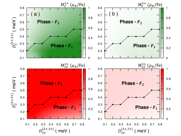
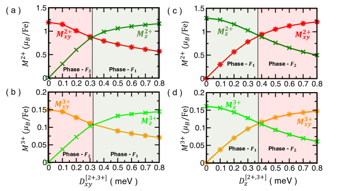
Our results (Fig. 3(b)) show the formation of non-collinear ferrimagnetic orders, where the FM ordered Fe2+ spins are oriented with respect to the AFM ordered Fe3+ sublattice ( denotes AFM order parameter), resulting in a net magnetization M. Without , the Fe2+ spins do not show any cooperative order. Three magnetic phases were identified, namely , and (Fig. 3(c)-(e)). aligns the major components of the Fe2+ and Fe3+ spins along the axis and in the plane, respectively, giving rise to longitudinal and transverse components of M as,
| (3) |
| (4) |
corresponds to co-planar mutually magnetic order with major and minor (induced by ) components. In , the major Fe2+ and Fe3+ spins are oriented in plane and along the axis, respectively. The stability of these phases is controlled by the complex interplay between the effective Fe2+-Fe3+ DM interactions,
| (5) |
and the SIA ( and ). Here, and . Both the direction and magnitude of are synchronized with (Fig. 2 and Sec. IV of the Supplementary Materials SM ).
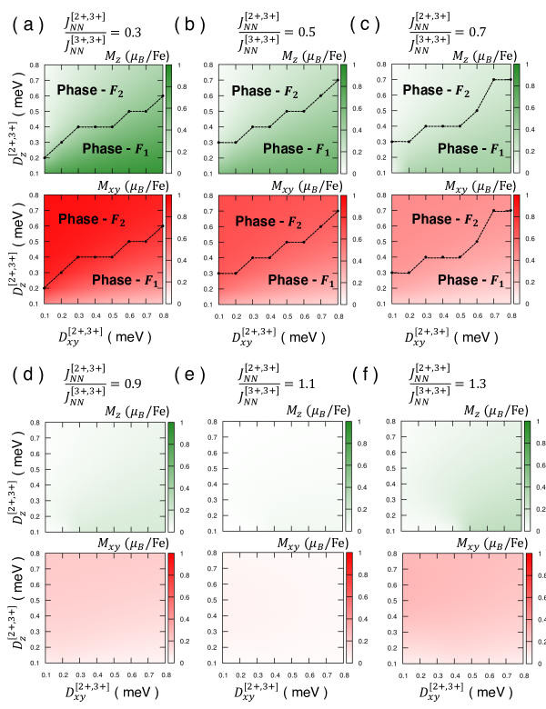
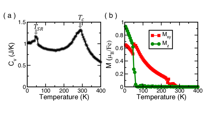
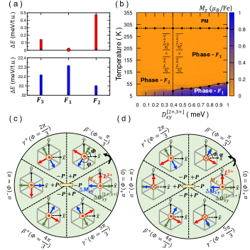
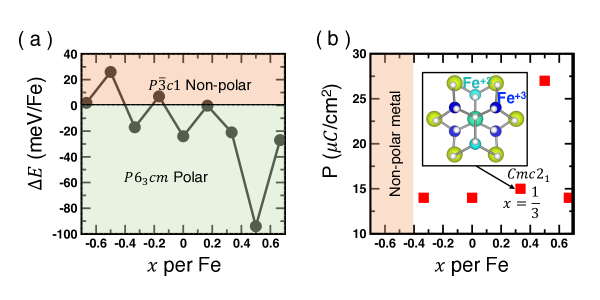
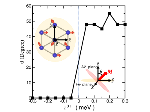
Next, we conducted GGA+ total energy calculations considering the polar and non-polar structures of the ferrimagnetic orders. The and ground state magnetic orders appear in the polar and the non-polar phases, respectively (Fig. 4(a)). These results are in harmony with the MC solutions obtained in the magnetic parameter space (Fig. 4(b)). This indicates SR transition with the modulation on the parameter synchronized with . Temperature also drives SR transition (Fig. 4(b)). At low temperature ( 5 K) cooperative order forms as . However, at high temperature order is formed due to entropy. The paramagnetic (PM) to ferrimagnetic phase transition temperature () is primarily determined by the relative strength, which also controls the magnitude of magnetization (Fig.S11 in the Supplementary Materials (SM, )). In the doped system, 290 K and 1.3 /Fe(see Fig.S12 in the Supplementary Materials (SM, )), both are significantly higher than their LuFeO3 counterparts (LFO113-1, ; LFO113-HD, ; LFO113-2, ; LFO113-3, ; LFO113-4, ), indicating an effective route to enhance the magnetic properties of LuFeO3.
The manipulation of P in these systems is complex in nature and not fully understood yet. However, the non-llinear coupling between P and is a well established fact (LFO113-HD, ; LFO-FE3, ). The process leads to either or rotation of by an angle (Fig. 4(c) and (d)). The tri-linear coupling between , M and (Eq. 3 and Eq. 4) and the coupling between and (Eq. 5 and Fig. 2) show that, () either reverses the direction of (reversing the direction of ) or that of . Moreover, formation of the ’clover-leaf’ vortex domain pattern (TPD-1, ; TPD-2, ; TPD-3, ; TPD-YU, ; TPD-4, ; TPD-5, ; TPD-6, ), suggests two probable ME domain structures. The first is characterized by the rotation of to its NN domain () leading both and to rotate in phase by . However, does not change its direction (Fig. 4(c)). In the second structure, the rotation of to its NN domain () induces both and to rotate out of phase by leading to the 180∘ switching of (Fig. 4(d). In the present system, process is expected to be more feasible, as the intermediate state exhibits lowest transition barrier height (Fig. 4(a) and (b)) and is associated with lower magnetostatic energy. This phenomenon opens up effective routes to achieve 180∘ ME switching via electric polling method (TPD-2, ).
In (LuFeO3)m/(LuFe2O4) superlattices, previous DFT calculations and EELS measurements showed the formation of the hole-doped LuFe2O4 ferrimagnetic tail-to-tail domain wall (LFO-JM1, ; LFO-JM2, ), transferring to the LuFeO3 layer forming head-to-head wall. Also, a coupling between and based on LuFe2O4 FE model was proposed, where an increase in the former led to a subsequent increase in the latter (LFO-JM1, ). Our present study, on the other hand, proposes doped LuFeO3 FE model, where localization of the doped in the form of C-type order and the formation of ferrimagnetic order can lead to a significant enhancement in M ( 2.4 - 4.0 per LuFe2O4 f.u.) (LFO-JM1, ) and a likely increase in . Additionally, it is expected to contribute to a complex ME switching process which is worth exploration.
In summery, we predict non-collinear ferrimagnetism, SR transitions and 180∘ ME switching phenomena governed by the coupling between charge ordering, DM interactions and improper ferroelectricity. These predictions are based on MC simulations on a two-sublattice model, constructed by doping the improper FE hexagonal phase of LuFeO3 with electrons. We elucidate the prospective microscopic mechanisms to control the stabilization of ferrimagnetic orders by applying electric field E induced SR transitions and 180∘ switching of the direction of M. Our proposed model will expectedly motivate the designing of non-collinear ferrimagnetic and ME materials with prospective applications in spintronics technology.
H.D. acknowledges the fruitful discussions with Saurabh Ghosh, M.J.Swamynadhan, Andrew O’Hara and Sokrates T. Pantelides. Research at the Tokyo Institute of Technology is supported by the Grants-in-Aid for Scientific Research No. 19K05246 from the Japan Society for the Promotion of Science (JSPS). H.D. also acknowledges computational support from TSUBAME supercomputing facility.
References
- (1) D. Treves, Phys. Rev. 125, 1843 (1962).
- (2) K. W. Blazey and G. Burns, Proc. Phys. Soc. 91, 640 (1967).
- (3) T. Yamaguchi, J. Phys. Chem. Solids. 35, 479 (1974).
- (4) Y. Tokunaga, S. Iguchi, T. Arima, and Y. Tokura, Phys. Rev. Lett. 101, 097205 (2008).
- (5) B. Rajeswaran, D. I. Khomskii, A. K. Zvezdin, C. N. R. Rao, and A. Sundaresan, Phys. Rev. B 86, 214409 (2012).
- (6) Y. Tokunaga, N. Furukawa, H. Sakai, Y. Taguchi, T. Arima and Y. Tokura, Nat. Mater. 8, 558–562 (2009).
- (7) H. J. Zhao, L. Bellaiche, X. M. Chen and J. Íñiguez, Nat. Commun. 8, 14025 (2017).
- (8) X. Ye, J. Zhao, H. Das, D. Sheptyakov, J. Yang, Y. Sakai, H. Hojo, Z. Liu, L. Zhou, L. Cao, T. Nishikubo, S. Wakazaki, C. Dong, X. Wang, Z. Hu, H.-J. Lin, C.-T. Chen, C. Sahle, A. Efiminko, H. Cao, S. Calder, K. Mibu, M. Kenzelmann, L. H. Tjeng, R. Yu, M. Azuma, C. Jin and Y. Long, Nat. Commun. 12, 1917 (2021).
- (9) L. Neél, Proc. Phys. Soc. A 65, 869 (1952).
- (10) E. W. Gorter, Nature 173, 123–124 (1954).
- (11) M. Kubota, T. Arima, Y. Kaneko, J. P. He, X. Z. Yu, and Y. Tokura, Phys. Rev. Lett. 92, 137401 (2004).
- (12) J. H. Jung, M. Matsubara, T. Arima, J. P. He, Y. Kaneko, and Y. Tokura, Phys. Rev. Lett. 93, 037403 (2004).
- (13) H. Ishizuka and Y. Motome, Phys. Rev. Lett. 109, 237207 (2012).
- (14) A. K. Nayak, M. Nicklas, S. Chadov, P. Khuntia, C. Shekhar, A. Kalache, M. Baenitz, Y. Skourski, V. K. G., A. Puri, U. Zeitler, J. M. D. Coey and C. Felser, Nature Materials 14, 679–684 (2015)
- (15) J. Girovsky, J. Nowakowski, Md. E. Ali, M. Baljozovic, H. R. Rossmann, T. Nijs, E. A. Aeby, S. Nowakowska, D. Siewert, G. Srivastava, C. Wäckerlin, J. Dreiser, S. Decurtins, S.-X. Liu, P. M. Oppeneer, T. A. Jung and N. Ballav, Nat Commun 8, 15388 (2017).
- (16) J. Seo, C. De, H. Ha, J. E. Lee, S. Park, J. Park, Y. Skourski, E. S. Choi, B. Kim, G. Y. Cho, H. W. Yeom, S.-W. Cheong, J. H. Kim, B.-J. Yang, K. Kim and J. S. Kim, Nature 599, 576–581 (2021).
- (17) S. K. Kim, G. S. D. Beach, K.-J. Lee, T. Ono, T. Rasing and H. Yang, Nat. Mater. 21, 24–34 (2022).
- (18) N. Bergeard, V. Loṕez-Flores, V. Halté, M. Hehn, C. Stamm, N. Pontius, E. Beaurepaire and C. Boeglin, Nat Commun 5, 3466 (2014).
- (19) J. Becker, A. Tsukamoto, A. Kirilyuk, J. C. Maan, Th. Rasing, P. C. M. Christianen, and A. V. Kimel, Phys. Rev. Lett. 118, 117203 (2017)
- (20) C. Kim, S. Lee, H.-G. Kim, J.-H. Park, K.-W. Moon, J. Y. Park, J. M. Yuk, K.-J. Lee, B.-G. Park, S. K. Kim, K.-J. Kim and C. Hwang, Nat. Mater. 19, 980–985 (2020).
- (21) M. Huang, M. U. Hasan, K. Klyukin, D. Zhang, D. Lyu, P. Gargiani, M. Valvidares, S. Sheffels, A. Churikova, F. B’́uttner, J. Zehner, L. Caretta, K.-Y. Lee, J. Chang, J.-P. Wang, K. Leistner, B. Yildiz and G. S. D. Beach, Nat. Nanotechnol. 16, 981–988 (2021).
- (22) D. Afanasiev, J. R. Hortensius, B. A. Ivanov, A. Sasani, E. Bousquet, Y. M. Blanter, R. V. Mikhaylovskiy, A. V. Kimel and A. D. Caviglia, Nat. Mater. 20, 607–611 (2021).
- (23) F. Wang, J. Kim, G. D. Gu, Y. Lee, S. Bae, and Y.-J. Kim, J. Appl. Phys. 113, 063909 (2013).
- (24) N. Ikeda, H. Ohsumi, K. Ohwada, K. Ishii, T. Inami, K. Kakurai, Y. Murakami, K. Yoshii, S. Mori, Y. Horibe and H. Kitô, Nature 436, 1136–1138 (2005).
- (25) A. D. Christianson, M. D. Lumsden, M. Angst, Z. Yamani, W. Tian, R. Jin, E. A. Payzant, S. E. Nagler, B. C. Sales, and D. Mandrus, Phys. Rev. Lett. 100, 107601 (2008).
- (26) H. J. Xiang and M.-H. Whangbo, Phys. Rev. Lett. 98, 246403 (2007).
- (27) Weida Wu, V. Kiryukhin, H.-J. Noh, K.-T. Ko, J.-H. Park, W. Ratcliff, II, P. A. Sharma, N. Harrison, Y. J. Choi, Y. Horibe, S. Lee, S. Park, H. T. Yi, C. L. Zhang, and S.-W. Cheong, Phys. Rev. Lett. 101, 137203 (2008).
- (28) K.-T. Ko, H.-J. Noh, J.-Y. Kim, B.-G. Park, J.-H. Park, A. Tanaka, S. B. Kim, C. L. Zhang, and S-W. Cheong, Phys. Rev. Lett. 103, 207202 (2009).
- (29) F. Wang, J. Kim, Y.-J. Kim, and G. D. Gu, Phys. Rev. B 80, 024419 (2009).
- (30) A. B. Harris and T. Yildirim, Phys. Rev. B 81, 134417 (2010).
- (31) M. Angst, R. P. Hermann, A. D. Christianson, M. D. Lumsden, C. Lee, M.-H. Whangbo, J.-W. Kim, P. J. Ryan, S. E. Nagler, W. Tian, R. Jin, B. C. Sales, and D. Mandrus, Phys. Rev. Lett. 101, 227601 (2008).
- (32) D. Niermann, F. Waschkowski, J. de Groot, M. Angst, and J. Hemberger, Phys. Rev. Lett. 109, 016405 (2012).
- (33) J. de Groot, T. Mueller, R. A. Rosenberg, D. J. Keavney, Z. Islam, J.-W. Kim, and M. Angst, Phys. Rev. Lett. 108, 187601 (2012).
- (34) S. Lafuerza, J. García, G. Subías, J. Blasco, K. Conder, and E. Pomjakushina, Phys. Rev. B 88, 085130 (2013).
- (35) J. A. Mundy, C. M. Brooks, M. E. Holtz, J. A. Moyer, H. Das, A. F. Réebola1, J. T. Heron, J. D. Clarkson, S. M. Disseler, Z. Liu, A. Farhan, R. Held, R. Hovden, E. Padgett, Q. Mao, H. Paik, R. Misra, L. F. Kourkoutis, E. Arenholz, A. Scholl, J. A. Borchers, W. D. Ratcliff, R. Ramesh, C. J. Fennie, P. Schiffer, D. A. Muller and D. G. Schlom, Nature 537, 523–527 (2016).
- (36) S. Fan, H. Das, A. Rébola, K. A. Smith, J. Mundy, C. Brooks, M. E. Holtz, D. A. Muller, C. J. Fennie, R. Ramesh, D. G. Schlom, S. McGill and J. L. Musfeldt, Nat Commun 11, 5582 (2020).
- (37) M. E. Holtz, E. S. Padgett, R. Steinhardt, C. M. Brooks, D. Meier, D. G. Schlom, D. A. Muller, and J. A. Mundy, Phys. Rev. Lett. 126, 157601 (2021).
- (38) E. Magome, C. Moriyoshi, Y. Kuroiwa, A. Masuno, and H. Inoue, Jpn. J. Appl. Phys. 49, 09ME06 (2010).
- (39) H. Das, A. L. Wysocki, Y. Geng, W. Wu, and C. J. Fennie, Nat. Commun. 5, 2998 (2014).
- (40) W. Wang, J. Zhao, W. Wang, Z. Gai, N. Balke, M. Chi, H. N. Lee, W. Tian, L. Zhu, X. Cheng, D. J. Keavney, J. Yi, T. Z. Ward, P. C. Snijders, H. M. Christen, W. Wu, J. Shen, and X. Xu, Phys. Rev. Lett. 110, 237601 (2012).
- (41) S. M. Disseler, J. A. Borchers, C. M. Brooks, J. A. Mundy, J. A. Moyer, D. A. Hillsberry, E. L. Thies, D. A. Tenne, J. Heron, M. E. Holtz, J. D. Clarkson, G. M. Stiehl, P. Schiffer, D. A. Muller, D. G. Schlom, and W. D. Ratcliff, Phys. Rev. Lett. 114, 217602 (2015).
- (42) J. A. Moyer, R. Misra, J. A. Mundy, C. M. Brooks, J. T. Heron, D. A. Muller, D. G. Schlom, and P. Schiffer, APL Mater. 2, 012106 (2014).
- (43) B. B. Van Aken, T. T. M. Palstra, A. Filippetti and N. A. Spaldin, Nat. Mater. 3, 164–170 (2004).
- (44) C. J. Fennie and K. M. Rabe, Phys. Rev. B 72, 100103 (2005).
- (45) S. Artyukhin, K. T. Delaney, N. A. Spaldin and M. Mostovoy, Nature Mater 13, 42–49 (2014).
- (46) Sec.I computational details of the first-principles density functional theory (DFT) calculations, Sec. II improper ferroelectric phases of the parent and doped LuFeO3, Sec. III computational details of the Monte Carlo simulations and detailed description of the and models, Sec.IV identified ferrimagnetic phases and Monte Carlo results.
- (47) N. A. Spaldin, Nat Rev Mater 2, 17017 (2017).
- (48) M. Fiebig, Th. Lottermoser, D. Fr’́ohlich, A. V. Goltsev and R. V. Pisarev, Nature 419, 818–820 (2002).
- (49) T. Choi, Y. Horibe, H. T. Yi, Y. J. Choi, Weida Wu and S.-W. Cheong, Nature Mater 9, 253–258 (2010).
- (50) Y. Geng, N. Lee, Y. J. Choi, S.-W. Cheong, and W. Wu, Nano Lett. 12, , 6055–6059 (2012).
- (51) Y. Kumagai and N. A. Spaldin, Nat Commun 4, 1540 (2013).
- (52) Y. Geng, H. Das, A. L. Wysocki, X. Wang, S-W. Cheong, M. Mostovoy, C. J. Fennie and W. Wu, Nature Mater 13, 163–167 (2014).
- (53) M. Lilienblum, T. Lottermoser, S. Manz, S. M. Selbach, A. Cano and M. Fiebig, Nature Phys 11, 1070–1073 (2015).
- (54) M. Giraldo, Q. N. Meier, A. Bortis, D. Nowak, N. A. Spaldin, M. Fiebig, M. C. Weber and T. Lottermoser, Nat Commun 12, 3093 (2021).
- (55) J. Zhang, P. V. Lukashev, S. S. Jaswal, and E. Y. Tsymbal1, Phys. Rev. B 96, 014435 (2017).
- (56) S. Li and T. Birol, Phys. Rev. Lett. 127, 087601 (2021).
- (57) I. V. Anisimov, F. Aryasetiawan, and A. I. Lichtenstein, J. Phys. Condens. Matter. 9, 767 (1997).
- (58) J. P. Perdew, K. Burke, and M. Ernzerhof, Phys. Rev. Lett. 77, 3865–3868 (1996).
- (59) G. Kresse and J. Hafner, Phys. Rev. B 47, 558–561 (1993).
- (60) G. Kresse and J. Furthmiiller, Phys. Rev. B 54, 11169–11186 (1996).
- (61) R. D. King-Smith and David Vanderbilt, Phys. Rev. B 49, 5828 (1994).
- (62) B. H. Bransden and C. J. Joachain, Physics of Atoms and Molecules (Longman Scientific & Technical, Essex, England, 1983), pp. 339–341.
- (63) N. Metropolis and S. Ulam, J. Am. Stat. Assoc. 44, 335 (1949).
- (64) N. Metropolis, A. W. Rosenbluth, M. N. Rosenbluth, and A. H. Teller, J. Chem. Phys. 21, 1087 (1953).
I Supplementary Materials
II I. DFT computational details
The first-principles calculations were conducted employing the density functional theory DFT+ method LDAU with the Perdew-Burke- Ernzerhof (PBE) form of exchange correlation functional PBE and using the projector augmented plane wave basis-based method as implemented in the VASP VASP1 ; VASP2 . We considered 4.5 eV and 0.95 eV as was used in the previous studiesLFO113-HD ; LFO-JM1 ; LFO-JM . We considered Lu 4 states in the core. Considering the polar and non-polar phases structural relaxations were performed for both parent LuFeO3 and the carrier doped systems employing 0.001 eV/Å convergence criteria of the Hellmann-Feynman forces. In the present study, the effect of excess carrier was simulated by changing the number of electrons in the calculation and adding a homogeneous background charge to keep the system neutral e-FE1 ; e-FE2 . We optimized the structures considering various magnetic orders. We used Monkhorst-Pack centred k-point mesh and a kinetic energy cut-off value of 500 eV. We calculated the electric polarization using the Berry phase method BP as implemented in VASP.
In order to estimate the symmetric exchange interactions between the magnetic ions, we conducted total energy calculations of multiple collinear spin orders. Additionally, the values of single-ion-anisotropy (SIA) parameters were calculated considering total energy of various non-collinear spin structures in the presence of spin-orbit () coupling as implemented in VASP SO .
III II. Improper ferroelectric phase
The paraelectric phase of LuFeO3 has symmetry. The phonon instability with irreducible symmetry at the zone-boundary point can lead to either a polar or a non-polar structure (see Fig. S1). The corresponding structural distortion patterns are depicted in Fig. S2. Employing GGA+ method we, therefore, optimized the polar and the non-polar structures by varying the concentration of carrier doping level, as shown in Fig. S3(a). We doped the system with both electrons and holes. As expected, the parent compound stabilizes in the phase with an electric polarization of 14 C/cm2 directed along the crystallographic c axis.
Interestingly, while most of the electron doped systems are expected to crystallize in the FE insulating phase, the majority of the hole doped systems tends to crystallize in the non-polar metallic phase (see Fig. S3(a)). In particular, our results show formation of Fe2+/Fe3+ charged ordered (CO) C-type state, similar to LuFe2O4, for electron doping level of per Fe. In the Cq-type state, in each Fe layer, Fe2+ triangular (T) lattice is situated within the Fe3+ hexagonal lattice, as shown in Fig. S3(b). The doped system crystallizes in the structure exhibiting strong distortions which induce a net polarization of 15 C/cm2 slightly tilted from the crystallographic c axis, as shown in Fig. S3(b).
IV III. Finite temperature Monte Carlo (MC) simulations
IV.1 A. Computational details
We performed classical Monte Carlo (MC) simulations using METROPOLIS algorithms MC1 ; MC2 and proper periodic boundary conditions as implemented in our group MC package, to study magnetic phase transitions as a function of temperature and magnetic parameters. We calculated total energy as a function of temperature () by considering number of MC steps for each temperature step and performing spin-flips. Here represents total number of Fe ions, respectively, in the MC supercell structure. During each spin-flip process it randomly rotates the direction of the selected spin with a uniform probability distribution of the associated unit spin vector over a unit sphere. The specific heat as a function of temperature was calculated employing,
| (S1) |
where the angles bracket denotes thermal average. We also calculated the magnetization of the system as a function of temperature as,
| (S2) |
where, represent component of M along the Cartesian axes , and , respectively. is the Bohr magneton and denotes the gyromagnetic ratio.
IV.2 B. Model
In the present study, we conducted MC simulations considering a spin model Hamiltonian of the parent system defined as,
| (S3) |
where the first term denotes the energy contribution due to the symmetric exchange (SE) interactions between Fe3+ spins and given by,
| (S4) |
it consists of nearest-neighbor (NN) and second-nearest-neighbor (2NN) in-plane SE interactions between Fe3+ () spins (see Fig. S4(a)). In the parent system, we considered that the Fe spins interact via six almost equivalent NN and six equivalent 2NN connecting pathways, as the difference in the strength of NN SE interactions mediated through non-equivalent planar oxygens (Op1 and Op2) is expected to be negligible. and denote the site of the Fe3+ spins and each pair was counted once. For the parent system, let us denote,
| (S5) |
In addition, SE interactions between the consecutive Fe layers mediated via Fe-O-Lu-O-Fe pathways, , were also taken into account. The distortion splits six equivalent inter-layer SE interactions into two and four non-equivalent SE interactions, namely and , respectively. The important parameter that contribute to stabilize a magnetic order in this structure is the effective inter-layer SE interaction defined as, .
| LuFeO3 | (meV) | (meV) | (meV) | - LuFeO3 | (meV) | (meV) | (meV) | (meV) |
| 6.3 (6.3∗) | 0.3 (0.5∗) | 0.4 (0.38∗) | 8.5 | 0.3 | 1.1 | -0.1 |
In order to estimate the values of these parameters for the parent system we calculated total energy of various spin configurations using a supercell of the structure. The estimated values are tabulated in Table S1.
In the paraelectric (PE) phase, only the NN DM interactions parallel to the axis are allowed and the symmetry adopted patterns are shown in Fig. S4(b) around the ion 1. The distortions induce the in-plane components, where around ion 1, two and four of the NN DM vectors form clockwise and anti-clockwise rotational patterns mediated via planar oxygen Op1 and Op2, respectively. (see Fig. S4(b)). Accordingly, let us define, and . However, previous DFT calculations indicate that LFO113-HD . Therefore, in order to simplify the spin model, we have used this postulate throughout the present study. The corresponding energy contribution of a single Fe layer () shown in Fig. S4(b) is given by,
| (S6) |
where the effective DM vectors can be defined as,
| (S7) | |||
| (S8) | |||
| (S9) |
Where represent the angle between the transverse component of the effective with axis. Also, and . As the consecutive Fe triangular layers, are connected through a axis, the associated effective transverse components of the DM vectors are anti-parallel to each other.
The SIA tensor of the Fe3+ ions consists of non-equivalent diagonal components () and off-diagonal components . Considering the zero trace condition, . In the PE phase and . Our present results and previous reports LFO113-HD suggest, . Additionally, to further simplify the model we assumed , as the effect of this off-diagonal component will be captured by the transverse component of the DM interactions. We therefore employed a simplified form of SIA tensor as,
| (S10) |
The positive and negative value of indicates uni-axial () and uni-planar () magnetic anisotropy, respectively. The DFT estimated values of SIA parameters are listed in Table S2.
| LuFeO3 | - LuFeO3 | ||||
|---|---|---|---|---|---|
| (meV) | (meV) | (meV) | (meV) | (meV) | |
| 0.03 (0.08∗) | 0.1∗ | 0.06∗ | 0.03 | 0.21 |
We report the results of Monte Carlo (MC) simulations performed on an 886 cell consisting of 2304 magnetic ions with spin value , and considering 109 MC steps for each temperature using the model Hamiltonian . The convergence of and the ground state magnetic structure were cross checked by considering upto 101010 ( 6000) cell size and 109 MC steps. We considered both cooling and heating processes to carefully cross check the stability of the magnetic phases. During these processes, the final simulated magnetic configuration corresponding to a particular temperature was considered as the initial magnetic configuration corresponding to the next value of temperature. We conducted finite temperature MC simulations considering a wide magnetic parameter space of DM interactions between the magnetic ions and as well as their SIA.
IV.3 C. Model
The electron doped system shows a transition from symmetry due the formation of C charge order. It introduces two magnetic sublattices, such as Fe2+ () triangular () and Fe3+ () hexagonal (). We incorporated the changes in the spin Hamiltonian accordingly,
| (S11) |
where the first term denotes SE interactions between magnetic ions and is given by,
| (S12) |
where and denote the site of the Fe2+ () and Fe3+ () spins in the and sublattices (see Fig. S7(a)), respectively. Similar to the parent system, we neglected the slight differences in the strength of the NN SE interactions and considered each Fe2+ spin interacts with NN Fe3+ spins mediated via six equivalent pathways, i.e. ,
| (S13) |
and with six equivalent 2NN Fe2+ spins as,
| (S14) |
On the other hand, the intra-Fe3+ sublattice interactions are described as,
| (S15) |
The estimated values of SE interactions are given in Table S1. The antiferromagnetic (AFM) NN interaction between Fe3+ spins increases under the influence of the doped electrons to a value of 8.5 eV. This behavior can be associated with the increase in the superexchange Fe-O-Fe pathways from (see Fig. S8). Note that, and superexchange connecting angles prefer AFM and ferromagnetic (FM) interaction, respectively. The is also AFM in nature, but almost an order of magnitude smaller than . This can be attributed to various factors, such as lowering of the Fe2+-O-Fe3+ (see Fig. S8) of the mediating pathways and FM components due to the Fe2+-Fe3+ multi-orbital hopping process. While within Fe3+ sublattice remains AFM in nature and weak, the interaction between Fe2+ spins was found to be FM and weak in nature.
The inter-layer SE interaction is complex in nature. Each Fe3+ ions experience four Fe3+-Fe3+ and two Fe2+-Fe3+ interactions mediated through long Fe-O-Lu-O-Fe pathways with an effective interaction . On the other hand, each Fe2+ ions experience four Fe2+-Fe3+ and two Fe2+-Fe2+ interactions mediated through long Fe-O-Lu-O-Fe pathways with an effective interaction . While we consider an effective of same strength and nature as of the parent system, i.e. 0.4 meV, we ignored in the present MC simulations.
In the doped structure considering the NN DM vector pattern same as the parent system, as depicted in S7(b), the energy contribution of a single Fe layer () is given by,
| (S16) |
Similar to the parent system we ignored the small non-equivalency effects. The effective DM vectors can be defined as,
| (S17) |
| (S18) |
| (S19) |
Where represent the angle between the transverse component of the effective with axis. For clarity we assumed . Also, , , and . As the consecutive Fe triangular layers are connected through a axis, the associated effective transverse components of the DM vectors are anti-parallel to each other.
Assuming similar postulates as developed in the case of the parent system, we therefore employed a simplified form of SIA tensor as,
| (S20) |
| (S21) |
The positive and negative value of () indicates uni-axial () and uni-planar () magnetic anisotropy of the Fe3+ (Fe2+) ions, respectively. The DFT estimated values of SIA parameters are given in Table S2.
Similar to model, we conducted MC simulations performed on the model considering an 886 cell consisting of 1536 Fe3+ () and 768 Fe2+ () magnetic ions, and considering 109 MC steps for each temperature using the model constructed through GGA+ calculations. The convergence of and the ground state magnetic structure were cross checked by considering upto 101010 ( 6000) cell size and 109 MC steps. We primarily conducted finite temperature MC simulations considering magnetic parameter space using the values of as estimated in the parent system and the estimated SIA parameters and SE interactions. This approach allowed us to explore the effect of on the stability of the magnetic order, as well as to develop the coupling between the magnetic order and the improper FE distortion , hence with electric polarization P.
V IV. Ferrimagnetic order
Finite temperature MC simulations predicted three ferrimagnetic phases. Two magnetic order parameters can be defined as, (1) net magnetization M of the sublattice and (2) AFM order in the H sublattice. As the magnetization is primarily contributed by the Fe2+ sublattice, as shown in Fig. S9, one can define the phase as,
| (S22) | |||
| (S23) |
The energy contribution due to Fe2+ - Fe3+ DM interaction is given by,
| (S24) |
where the effective DM interactions are defined as, and . One can derive,
| (S25) | |||
| (S26) |
Which display the coupling between , M and . Following these approach one can define phase and . The stability of these phases strongly depends on the complex interplay between the magnetic interactions (see Fig. S9-S11) and temperature. Hence, subtle changes in the structure is expected to drive spin-reorientation transitions.