Geometrically programmed self-limited assembly of tubules using DNA origami colloids
Abstract
Self-assembly is one of the most promising strategies for making functional materials at the nanoscale, yet new design principles for making self-limiting architectures, rather than spatially unlimited periodic lattice structures, are needed. To address this challenge, we explore the trade-offs between addressable assembly and self-closing assembly of a specific class of self-limiting structures: cylindrical tubules. We make triangular subunits using DNA origami that have specific, valence-limited interactions and designed binding angles, and study their assembly into tubules that have a self-limited width that is much larger than the size of an individual subunit. In the simplest case, the tubules are assembled from a single component by geometrically programming the dihedral angles between neighboring subunits. We show that the tubules can reach many micrometers in length and that their average width can be prescribed through the dihedral angles. We find that there is a distribution in the width and the chirality of the tubules, which we rationalize by developing a model that considers the finite bending rigidity of the assembled structure as well as the mechanism of self-closure. Finally, we demonstrate that the distributions of tubules can be further sculpted by increasing the number of subunit species, thereby increasing the assembly complexity, and demonstrate that using two subunit species successfully reduces the number of available end states by half. These results help to shed light on the roles of assembly complexity and geometry in self-limited assembly and could be extended to other self-limiting architectures, such as shells, toroids, or triply-periodic frameworks.
Self-assembly is a fundamental building principle used by Nature to make functional materials, including virus capsids for encapsulation and delivery [1], cytoskeletal filaments for transport [2], and macromolecular machines with diverse roles, like the ribosome for protein synthesis [3]. Recently, there has been considerable effort aimed at mimicking biological self-assembly to synthesize user-prescribed structures from synthetic nanometer- and micrometer-scale particles. For example, by encoding short-range specific interactions, DNA-grafted colloidal particles can be programmed to assemble into a variety of two- and three-dimensional crystal phases with prescribed symmetry groups and lattice constants [4, 5, 6, 7]. However, rather than unbounded crystal phases, the aforementioned biological functionalities—encapsulation, motility, and protein synthesis—arise from self-limiting structures that have one or more self-limited length scales.
How does one go beyond periodic lattice structures with macroscopically uncontrolled dimensions, to program the assembly of self-limiting architectures that have self-limited length scales that are arbitrarily large with respect to the size of the individual subunits [8]? There are two prominent paradigms for prescribing self-limited assembly: 1) addressable assembly and 2) self-closing assembly. In addressable assembly, every component of a multi-species ensemble is distinct and is programmed to occupy a specific location within a target structure [9, 10, 11]. Therefore, increasing the self-limited length scale necessitates increasing the assembly complexity in terms of the number and interaction specificity of the subunits. In self-closing assembly, anisotropic interactions give rise to the accumulation of curvature during growth that causes the structure to self-close at a finite size [8]. In contrast to addressable assembly, the self-limited length scale in self-closing assembly is therefore controlled by the binding angles between neighboring subunits and is programmed geometrically rather than through specific interactions, and as such, may require only one or relatively few subunits to target a specific self-closing size. But which strategy should one select for a particular target geometry, and which approach is more accurate, precise, or economical? Because the vast majority of examples either address only one paradigm or do not distinguish between the two, as in DNA-coated colloids [12], DNA tiles [13, 14, 15, 16, 17], hierarchical assembly of DNA origami [18, 19, 20] and designed proteins [21, 16], direct comparisons between addressability and geometry in prescribing self-limited assembly are obscured.
In this article, we create an experimental platform using DNA origami for examining the roles of geometric and interaction specificity in arguably the simplest system that could in principle be programmed by geometry alone: the assembly of cylindrical tubules from rigid triangular monomers. The tubule is the ideal target geometry because it represents an infinitely large class of structures, each of which can be assembled from a single subunit species by controlling the dihedral angles between neighboring subunits. As anticipated, we show that we can vary the self-limited width of the tubules by tuning the dihedral angles between neighboring subunits without changing the interaction complexity. However, we find that the width of the assembled tubules takes a range of values and that the distribution broadens upon increasing the mean tubule width. We discuss how this distribution of the self-limited width is a generic feature of self-closing assembly when the self-limited length scale is sufficiently large compared to the size of the building block [22], which we understand using a simple theory. We conclude by exploring how increasing the assembly complexity enables us to constrain the width distribution by using multiple species of triangles with increased numbers of specific interactions. For a binary mixture of triangle species, we validate that the allowed states of the assembled tubules are reduced by half, as expected from simple geometrical arguments.
Results and Discussion
.1 Design principles
Our system consists of rigid triangular subunits made by DNA origami [20] that encode all of the information necessary to self-assemble tubules with user-prescribed geometries (Fig. 1A). Assembling tubules from triangular subunits requires that we specify two types of information: 1) the interaction specificity between the edges and 2) the local curvature between neighboring subunits. We encode the specific interactions by using unique protrusions and recesses that give rise to shape-complementary lock-and-key interactions whose attraction originates from blunt-end stacking (Fig. 1B) [23]. At a minimum, we require three specific interactions—one per side—which are each homophilic. These three specific interactions allow the triangular subunits to assemble into a deterministic triangular lattice, where each side aligns with one of the three lattice directions.
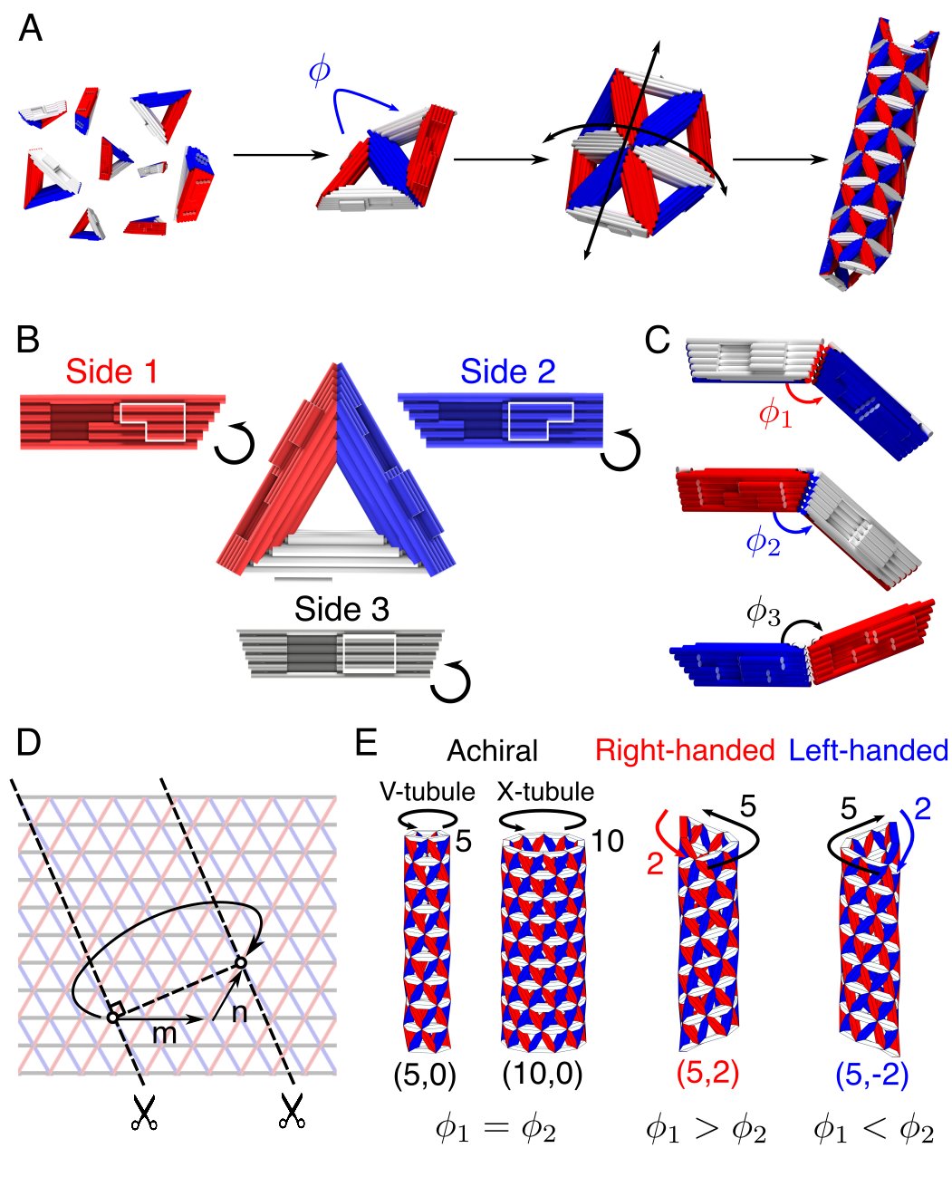
Additionally, we encode the local curvature by specifying the dihedral angles between neighboring subunits. Specifically, we design the bevel angles of each side of the triangular subunit such that it forms the three dihedral angles with its three neighbors corresponding to a target tubule geometry (Fig. 1C). For example, the subunit in Fig. 1B–C, which assembles into a tubule with five subunit edges in circumference, has dihedral angles of 138.2, 138.2, and -158.4 degrees for sides 1, 2, and 3, respectively. The accumulation of curvature from the dihedral angles upon assembly results in the formation of a curved triangular lattice. For appropriately chosen angles, the lattice will close upon itself to form a tubule (Fig. 1D), which can be chiral or achiral depending on how the tubule closes (Fig. 1E). See Supplementary Information II for more details of the tubule geometry.
Because the curvature originates from the combination of three bevel angles, the width, handedness, and pitch of the resulting tubules can be programmed using these three angles alone. Indeed, the final tubule structure is equivalent to the equilateral Yoshimura pattern of a buckled cylindrical shell [24], which constitutes a class of origami tilings of cylinders via a single triangular facet with a single set of fold angles on its three edges. In the case of tubules, larger dihedral angles in the direction perpendicular to the tubule axis produce wider tubules. Furthermore, setting the dihedral angles of sides 1 and 2 to different values produces chiral tubules with different pitch and handedness (Fig. 1E). The relative magnitude of the two dihedral angles determines the handedness and the difference between the two angles determines the pitch, with a larger difference leading to a larger pitch. Thus, by tuning the dihedral angles of the three sides, we can assemble a variety of different tubule structures. We note that the ability to program any tubule geometry using a single triangular facet is in contrast to the ability to program assembly of an icosahedral shell, for example, which requires a larger and larger number of unique facets upon increasing the shell diameter [1, 20].
The resulting tubules can be uniquely classified using a pair of lattice indices, [25]. Here, refers to vector along side 3 of the triangle and refers to the vector along side 1 () or side 2 (). Therefore, defines the shortest distance along the triangular lattice to go around the tubule and come back to the same vertex. Note that we only consider the case . With our convention, we use the positive index to define right-handed tubules and the negative index for left-handed tubules. Each tubule type is associated with a different set of dihedral angles for the three sides.
.2 Tubule assembly
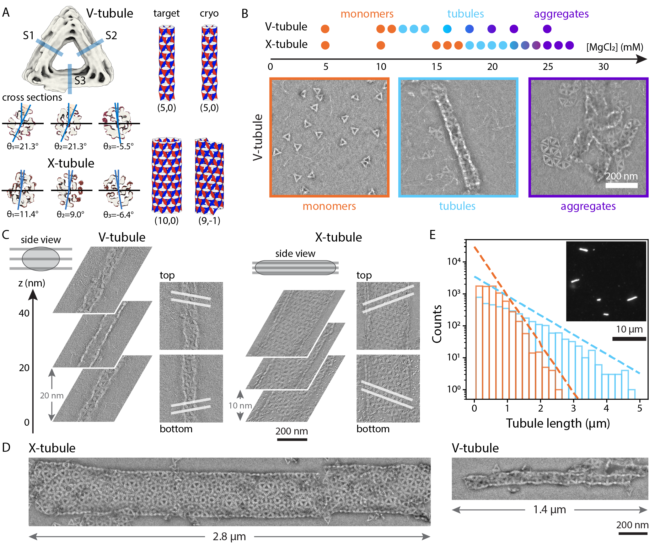
To demonstrate the utility of our experimental approach, we design two different monomers that assemble into tubules with different widths: V-triangle, which targets a (5,0) tubule, and X-triangle111Roman numerals V and X are used as shorthand for the target tubule types (5,0) and (10,0) respectively., which targets a (10,0) tubule (Fig. 2A). Each side of the triangle has a cross-section that is 4-by-6 double helices arranged on a square lattice (Fig. S3A). We specify the three unique bevel angles required for a particular tubule geometry by varying the relative lengths of the double helices (Fig. S3B). We encode the specific shapes of the protrusions and recesses by designing the scaffold routing, which we choose to disallow off-target binding and to enforce the correct relative orientations of neighboring subunits. The size of the subunits is set by the length of the DNA scaffold, which is 8064-nucleotides long. See Supplementary Information III for details of the subunit design.
We fold, purify, and assemble the subunits using standard DNA origami protocols. In brief, we fold the origami using a slow, linear temperature ramp, purify the resulting monomers by gel extraction, and then assemble them at constant temperature for one week in a rotating incubator [26] (see Supplementary Information V). For a given design, we perform multiple assembly experiments at different concentrations of MgCl2 to tune the strength of the intersubunit attraction. Finally, we characterize the structures of the individual monomers using single-particle cryogenic electron microscopy (cryo-EM) [27] and the entire assemblies using negative-stain transmission electron microscopy (TEM).
The bevel angles of the folded monomers are close to the target values but do not match them exactly. By fitting a pseudo-atomic model to our cryo-EM reconstructions [28] we make an estimate of the bevel angles of each of the three sides for both of our monomers (Fig. 2A). We find that for the V-triangle the three sides have angles of () compared with the target angles of (). Comparing these angles to the angles of different tubule types, this monomer is closest to a () tubule, as designed. In contrast, for the X-triangle, we see monomer bevel angles of () compared with (), yielding a closest state of a () tubule. While the () tubule has a similar diameter to the () one, it is chiral and left-handed rather than achiral, as in the designed monomer. See Supplementary Information VIII for more detail on the cryo-EM reconstructions.
The assembly of the triangular subunits into self-limiting structures depends on the intersubunit attraction, which can be controlled by varying the concentration of MgCl2. For both designs, we observe the same sequence of outcomes upon increasing the Mg2+ concentration (Fig. 2B). At low Mg2+ concentration, we observe only monomers and oligomers containing a few subunits. At intermediate Mg2+ concentration, we see the assembly of filament-like, self-limited structures in coexistence with monomers. The fact that we observe the coexistence of assemblies and monomers suggests that assembly occurred near to equilibrium and that the assembled filaments likely grew by consuming monomers rather than the merging of clusters. At higher Mg2+ concentrations, we observe large disordered aggregates and rarely observe monomers or small clusters. Therefore, we hypothesize that these large aggregates are likely due to kinetic arrest [29]. These results are consistent with previous measurements of the stacking interactions between blunt ends, which show that the interactions become stronger upon increasing Mg2+ concentration [30].
TEM tomography confirms that the filament-like structures are indeed tubules. First, we observe a single filament assembled from V-triangles (Fig. 2C). Looking at different slices through the filament in the direction normal to the EM grid, or -stack, we see that the structure clearly shows two triangular lattices at different positions, separated by a hollow core. The distance between the top and bottom lattices is around 40 nm, which is shorter than the expected diameter of 88 nm, but longer than 20 nm, or twice the thickness of a triangle. Therefore, we hypothesize that the cross-section of the tubule deposited on grid is elliptical. Finally, we also see that the top and bottom lattices have different orientations of the triangular lattice with respect to one another, as would be expected for a chiral tubule. Taken together, these observations confirm that the filament is indeed a tubule. Going further, the lattice orientation can be tracked around the tubule, yielding a (4,1) tubule for this case. While this determination only gives us the magnitude of n, we also determine the handedness by comparing our reconstructions to reconstructions of a DNA origami nanohelix labeled with gold nanoparticles in a right-handed, chiral arrangement (see Supplementary Information VII B) [31, 32].
Similarly, we find that the wider filaments formed from X-triangles are also tubules. As with the V-triangles, the tomograms of the wide filaments show two triangular lattices, which are mirror images of one another, and spaced apart along the direction. In this case, the distance between the bottom and the top lattices is around 20 nm, which matches the height of two triangles. We suspect that this spacing is due to the flattening of the X-tubule during the sample preparation. This hypothesis is further supported by the observation that the two triangular lattices appear to be planar, as expected for a flattened tubule. Finally, similar to the example V-tubule, the specific X-tubule shown in Fig. 2C is also chiral and right-handed, as seen in the mirror reflection of the top and bottom lattices (see Supplementary Information VII B).
Remarkably, we find that both V-tubules and X-tubules can grow to micrometers in length and exhibit length distributions that are characteristic of equilibrium one-dimensional growth. Figure 2D shows examples of some of the longest tubules that we observe in electron microscopy for both designs. The V-tubule is roughly 1200 nanometers in length and is made from about 210 subunits. The X-tubule is nearly 3 micrometers long and is assembled from about 1400 subunits. To complement our EM observations, we also perform epi-fluorescence experiments to get a more complete view of the tubule lengths (Fig. 2E, see Supplementary Information VII A for details). We find that both V- and X-tubules are characterized by length distributions that decay exponentially, with means of 0.5 micrometers and 0.9 micrometers, respectively, which is consistent with expectations for equilibrium one-dimensional assembly [33]. In the extremes, we find assemblies reaching up to 5 micrometers in length. Comparing our X-tubule results to earlier attempts to assemble tubules of similar width from DNA origami subunits [19] shows that our approach yields assemblies that are roughly an order of magnitude longer and contain about five times the number of subunits. Furthermore, our results show that although the width of the tubule is self-limited, the tubule lengths are unconstrained.
.3 Tubule distributions
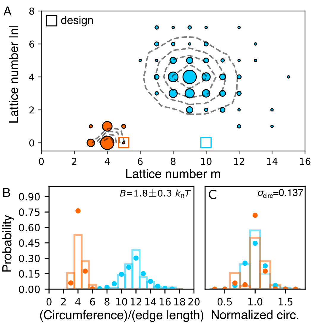
Whereas the results above show the structure of single tubules, our assembly experiments yield an ensemble of tubules that exhibits a variety of widths and lattice orientations, despite being formed from a single monomer type. For both the V- and X-tubule designs, we identify the pair of indices () that classifies the structure for each of hundreds of individual tubules, and create a distribution (Fig. 3A). The distribution shows that the most probable tubule types are (4,0) and (9,4) for the V- and X-tubules respectively, with the probability of different states falling off with distance from this tubule type. Furthermore, we find that the breadth of the X-tubule distribution is larger than that of the V-tubule. Although we cannot easily determine the chirality of every tubule, we examined 13 chiral V-tubules and 15 chiral X-tubules using tomography. In both cases, all of the tubules that we examined were right-handed. See the Supplementary Information VII B and VII C for a detailed description of the tubule classification.
The observed distributions beg two important questions: 1) Why are the tubule distributions not centered around the target structures? and 2) What determines the breadth of the tubule distribution around the most probable tubule type? We address the first question by returning to our single-particle reconstructions of the monomers from cryo-EM (Fig. 2A). While the V-triangle estimates a state close to the peak of the experimental distribution, the X-triangle estimate is 13% narrower in width than the (9,4) peak that we observe. We note that the cryo-EM map of the X-triangle shows that some parts of the lock-and-key design protrude from the structure due to a missed crossover in the origami design (Fig. S16). Therefore, we hypothesize that this aspect of the structure causes a poor fit for the lock-and-key shapes of the interaction, leading to unintended torques that could skew the dihedral angles to a different value. This misfit would cause a shift in the mean of the distribution away from what is expected from the geometry of the monomer alone.
Next, we tackle the origin of the breadth of the distribution. We start by noting that tubules with neighboring lattice numbers only vary by small changes in their dihedral angles. Therefore, if the bending rigidity of the assembly is sufficiently small, thermal fluctuations will cause the dihedral angles between neighboring triangles to explore a range of possible values, leading to tubules with larger or smaller diameters.
This idea can be captured by considering the Helfrich energy of an elastic sheet, where is the surface area, is the bending rigidity, and is the fluctuation of the sheet’s curvature in the circumferential direction [34]. We assume that as the assemblies grow, they must first form a patch-like circular sheet before closing into a tubule. Thermal fluctuations will cause this sheet to accommodate different curvatures from its preferred value, but once it grows large enough to close into a tubule we assume that it can not open into a sheet again, thereby locking in a specific tubule circumference. If the growth rate is faster than the dissociation of a subunit-subunit bond, then once a tubule forms and starts to grow, the possibility of opening a large number of bonds to allow the tubule to reform into a different type becomes increasingly unlikely. Therefore, we estimate the size of assemblies at this closure point as a disk with a diameter that corresponds to the circumference of the closed tubule. The fluctuations of the sheet’s curvature at the point of closure will inherently lead to a distribution of tubule circumferences. Under these assumptions, we can write the Helfrich energy for a tubule at closure as
| (1) |
where is the circumference of a tubule. Assuming that the circumferences follow a Boltzmann distribution, , we can relate the spread of the widths to the bending rigidity ([22], see Supplementary Information IX for details).
The predictions from the Helfrich energy are consistent with our experimental observations, suggesting that the width distribution is determined by the bending rigidity of the growing assembly and the irreversibility of closure. Figure 3B shows the distribution of the tubule circumference for both V- and X-tubules. Following the insight we gained from considering the Helfrich energy, we rescale the circumference by the mean circumference of each distribution. Figure 3C shows that for both V- and X-tubules the scaled distributions have similar breadths, with standard deviations of 0.149 and 0.125, respectively. The importance of this observation is that it is an inherent feature of self-closing assemblies at finite temperature: Whenever the assembly has a finite bending rigidity, the system will form a distribution of end states with a breadth that depends on the self-limited length scale relative to the size of the subunit.
Using the variance of the width distributions, we make an estimate of the bending rigidity of the V- and X-tubules. Assuming both assemblies have the same bending rigidity, we find . To our knowledge, this is the first estimate of bending rigidity of shape-complementary interactions in DNA origami. Moreover, we can use this bending rigidity as an input to perform more detailed energetics calculations (see Supplementary Information IX) to get a complete () distribution for the expected tubules [22], which is shown in the contours of Fig. 3A. Similarly, we can compute the circumference distributions for the model. In both cases, we find that our model predictions match the experimental data well (Fig. 3B), further supporting the idea that the distribution of tubules we observe in the experiment is due to finite bending rigidity and is therefore expected for self-closing structures.
.4 Pruning the tubule distribution by increasing the assembly complexity
Our observations of the X-tubule assembly highlight an inherent challenge in using self-closing assembly alone to target finite-sized soft materials: As we target larger self-closing lengths, the distribution of the self-limited dimension also gets broader. So how do we overcome this challenge to assemble wider tubules without compromising the accuracy of the assembly?
Here we turn our attention toward the other paradigm for encoding self-limitation: addressable assembly. The rationale of this approach is relatively easy to understand. By increasing the number of particle species per structure, and therefore the total number of specific interactions, the location of any given particle within that structure becomes more precisely defined. In the fully-addressable limit, each particle species can only occupy a single position within the final structure while simultaneously maximizing the number of its favorable interactions. Therefore, by eliminating the other ways in which the particles can be arranged, the yield of the target assembly can be increased.
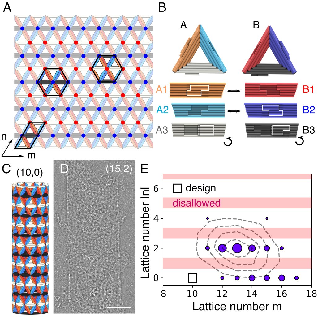
We explore this approach by assembling a (10,0) tubule from two unique species of triangular subunits. Figure 4 shows our specific realization of this concept using a binary tiling that is compatible with tubule self-assembly (Fig. 4A, see Supplementary Information IV). The two species are placed periodically and unidirectionally in the pattern. Since each side encodes a specific dihedral angle, the sides must always remain in the same orientation. As before, a triangular lattice of these two species can be rolled up into a (10,0) tubule. However, unlike before, the binary lattice contains two distinct types of vertices. As a result, the assembled tubules have an additional constraint: When the triangular lattice closes to form a tubule, the closing vertices must match. Therefore, for our specific case, we expect that only tubules with an even lattice number can assemble. The specific implementation of the lock-and-key geometries and their interactions is shown in Fig. 4B and the expected assembly is shown in Fig. 4C.
The distribution of assembled tubules demonstrates that increasing the assembly complexity limits the accessible states. Figure 4D shows an example tubule and Fig. 4E is the tubule distribution that we measure. We find that the distribution is maximal at (13,2), with some tubules being chiral and others achiral. All 7 tomography reconstructions of chiral tubules were identified to be right-handed (see Supplementary Information VII B). Most importantly, we do not find a single tubule classified by an odd value of , as we intended by our design. We also find that the probability of the most common state is increased compared to what it would be with a single particle type. The binary assembly has a larger average circumference than the X-tubule, which would suggest that the probability for the most common state would be comparatively lower. However, we find that the most populated state for the binary assembly is 22.1% compared to 17.6% for the X-tubule. This increase in probability is a result of using more species of triangles for the assembly since some fraction of tubules that might have had an odd are distributed to nearby even states.
As before, although the distribution is not centered around the target state, it has a width that is consistent with our energetics model. We hypothesize that the shift in the center of the distribution is again due to the experimental design challenge of accurately encoding the dihedral angles in our DNA origami subunits. The bevel angles of the triangles are designed to target X-tubules, similar to the previous case. However, cryo-EM reconstructions of the individual subunits reveal bevel angles that would target a (13,-1) tubule (see Supplementary Information VIII).
Conclusion
In summary, we devised a new class of colloidal particles using DNA origami and studied the roles of geometry and interaction complexity in their self-limited assembly into tubules. Our DNA origami design scheme allows for control over the valence, interaction specificity, and local curvature of the subunits, independently. We demonstrate that the new DNA origami colloids enable the assembly of complex structures, such as tubules, with self-limited dimensions that are much larger than the individual subunits. Using this design principle, we designed and assembled tubules of different widths, demonstrating that information encoded in the geometry of individual subunits can be used to program the geometry of the entire assembly. However, due to the intrinsic flexibility of the binding, tubules with a variety of widths and chiralities assembled from the same subunits, which was especially prominent for wider tubules. Such a distribution of assembled tubules for a single monomer type is an inherent feature of bending fluctuations in curvature-limited assemblies.
Here, we experimentally demonstrated one path toward removing off-target structures to focus the distribution on the target of interest. The precision in reaching a specific state can be increased by combining interaction specificity with geometric specificity in a multi-species design. As one specific realization of this concept, we assembled tubules using two species of subunits, which effectively reduced the number of accessible states by half. Therefore, as more species of subunits are added to the system, we anticipate that the yield of the target state will increase, though likely at the cost of longer timescales for assembly [22]. Another possibility other than interaction specificity that follows from our observations is that one can exploit the geometric specificity of the system to mitigate the formation of off-target structures. For example, designing ever more rigid binding sites should increase the energetic cost to deform the structure away from the target geometry. While it is not clear how much control there is over this aspect given the material properties of the subunits themselves, one might expect the bending rigidity to vary with the particle aspect ratio (i.e. thickness to width) based on elastic considerations alone. Finally, Nature, confronted with the same design challenge of assembling tubules from few components, has evolved a third strategy for eliminating off-target states: employing seeded nucleation, as seen with the in vivo assembly of microtubules [35, 2, 36]. Thus, if one can tune the supersaturation level to avoid spurious nucleation while still allowing for growth by monomer addition, having templates off of which tubules grow would improve the specificity of a given target structure without impeding the kinetics [17].
A somewhat surprising result of the origami design is how different the bevel angles of the three different versions of the X-triangle are (see Supplementary Information Table IV). Even though all three of these structures were constructed using the same design principle, resulting in the same length of scaffold strands for each helix, this approach did not result in the same bevel angles for the different sides. One main difference is that the crossover connections between helices had to be placed in different locations to accommodate the different lock-and-key designs. This subtle change may cause unintended torsion within the sides that impact the relative angles of adjacent sides. One avenue to address this issue would be to use interior supporting struts to add additional length constraints to the system. Another possible issue is that the short (one to three base pairs) single-stranded DNA segments connecting helices at the vertices might over constrain the vertices and add stress to the subunit. A design modification that might avoid this issue is to only connect the sides at the vertices in a few locations. Lastly, it seems prudent to use existing simulation software, such as oxDNA [37], ENRG MD [38], and mrdna [39] to screen different arrangements of crossovers to find ones that yield the desired bevel angles.
Overall, our DNA origami colloids represent a powerful platform for programming the assembly of self-limiting architectures. We argue that our ability to program the local curvature with the precision of a few degrees per subunit opens up new directions in materials design that surpass what is currently possible. Whereas tubules assembled from DNA tiles are made from ‘floppy’ components and therefore prescribed mainly by the interaction specificity encoded in the tile sequences [13, 14, 15, 16], our tubule structures can be programmed by both interaction specificity and geometrical specificity. As we showed, these two paradigms can play important complementary roles in self-limited assembly. Geometric specificity can enable economical designs that require only a few subunit species and interaction specificity can improve the accuracy of assembly by eliminating off-target structures. Therefore, going forward, we anticipate that being able to prescribe both mechanisms of self-limited assembly will allow access to a new library of self-assembled structures with interesting material applications. Examples include 2D lattice-like membranes for patterning or separations [40, 18], spherical shells for encapsulation and delivery [20], fibers or length-limited tubules through geometrical frustration [41, 42], and three-dimensional3D periodic structures for structural coloration [43].
Materials and Methods
Brief descriptions of our experimental methods are provided below. For more detailed methods see the Supplementary Information I.
Assembly of triangular subunits
DNA origami subunits are assembled in a one-pot reaction with 50 nM of p8064 scaffold DNA (Tilibit) and 200 nM of each staple strand (IDT, see Supplementary Information for sequences) in a standard ‘folding buffer’. Standard ‘folding buffers’, described previously [26], contain mM MgCl2, 5 mM Tris base, 1 mM EDTA, and 5 mM NaCl (FoB). Reaction solutions are subjected to a thermal annealing cycle in a Tetrad (Bio-Rad) thermocycler. Optimal MgCl2 concentrations and annealing protocols are described in Supplementary Information Table S1.
Purification of subunits
All origami subunits are purified by gel extraction and concentrated by ultrafiltration. We use a 1.5% agarose gel with 0.5XTBE buffer, 5.5 mM MgCl2, and 0.5x SYBR-safe (Invitrogen). Custom-made gel combs that can hold 0.2 ml per well were used to increase the throughput. The folded solution is mixed 5:1 with loading dye (30% w/v Ficoll 400, 0.1% w/v bromophenol blue, 3xTBE) and run at 110V for 2 hours. We remove the monomer band with a razor blade and dice it into small pieces. Gel pieces are placed in a Freeze ’N Squeeze spin column (Bio-Rad) and kept at -20∘ C for 5 minutes, then spun down for 5 minutes at 13 krcf. The subnatant is concentrated by ultrafiltration with 0.5 ml Amicon 100 kDa filters. Amicon filters are first equilibrated by centrifuging down 0.5 ml of 1xFoB5 at 5 krcf for 7 minutes, after which the flow-through is removed. The DNA origami solution is added up to 0.5 ml and centrifuged at 14 krcf for 15 minutes, then the flow-through is removed. This process is repeated until all of the DNA origami solution has been filtered. Finally, we place the filter upside down over a new Amicon tube and centrifuge at 1 krcf for 2 minutes. The DNA origami concentration of the final solution is measured using a Nanodrop (Thermo Scientific).
Self-assembly of tubules
Purified subunits are assembled in 50 l mixtures of 1xFoB with a monomer concentration of 10 nM. The MgCl2 concentration () is varied from 5 to 30 mM. The assembly solution is pipetted into a capped 0.1 ml strip tube (Rotor-Gene), which is subsequently place into a 0.2 ml strip tube (Corning) to suppress evaporation and condensation within the tube. Tubes are loaded into a rotating incubator (Roto-Therm, Benchmark Scientific) at 40∘ C for a week.
Negative stain TEM
Assembly samples are incubated on glow-discharged FCF400-Cu TEM grids (Electron Microscopy Sciences) for 60–120 s. Grids are then stained with 2% aqueous uranyl formate solution with 20 mM NaOH for up to 30 s before blotting on filter paper and using vacuum suction to remove excess fluid. Images of the grids are acquired on an FEI Morgagni TEM operated at 80 kV with a Nanosprint5 CMOS camera (AMT) at magnifications between x8000 and x20000. Tomograms of grid samples are acquired on a Tecnai F20 TEM with an FEG run at 200kV with a Gatan Ultrascan 4kx4k CCD camera. Tilt series were observed at a magnification of x32000 from -50∘ to 50∘ in 2∘ increments. Subsequent analysis is performed using Etomo (IMOD [44]).
Cryo-electron microscopy
Higher concentrations of DNA origami are used to prepare cryo-EM grids, summarized in SI Table S3. Samples are placed on glow-discharged C-flat 1.2/1.3 400 mesh grids (Protochip). Plunge-freezing of the grids in liquid ethane is performed with an FEI Vitrobot with sample volumes of 3 l, blot times of 5–8 s, a blot force of -1, and a drain time of 0 s at 20∘ C and 95% humidity. All cryo-EM images were acquired with a Tecnai F30 TEM with the field emission gun electron source operated at 300kV and equipped with an FEI Falcon II direct electron detector at a magnification of x39000. Single-particle acquisition was performed with SerialEM. The defocus was set to -2 m for all acquisitions with a pixel size of 2.87 Angstrom.
Image processing was performed using RELION-3 [27]. Contrast-transfer-function (CTF) estimation was performed using CTFFIND4.1 [45]. After picking single particles we performed a reference-free 2D classification from which the best 2D class averages were selected for processing, estimated by visual inspection. The particles in these 2D class averages were used to calculate an initial 3D model. A single round of 3D classification was used to remove heterogeneous monomers and the remaining particles were used for 3D auto-refinement and post-processing. A summary of the cryo-EM reconstructions is shown in SI Table S3.
Epi-fluorescence imaging of tubules
To dye our samples, we incubate our assemblies with YOYO-1 dye (Invitrogen) at room temperature for at least half an hour in a solution of 5 nM DNA origami, 500 nM YOYO-1 dye, and 1xFoB, at the same MgCl2 concentration as that of the assembly. We pipette 1.6 l of the solution onto a microscope slide that has been cleaned with Alconox, ethanol (90%), acetone, deionized water, and subsequently plasma-cleaned. After deposition, a plasma-cleaned coverslip is placed on top to create a thin liquid layer. Samples are then imaged on a TE2000 Nikon inverted microscope with a Blackfly USB3 (FLIR) camera.
Acknowledgements.
We acknowledge Don Caspar for sparking an interest in the self-assembly of cylindrical tubules. We thank Botond Tyukodi and Farzaneh Mohajerani for helpful discussions, Thomas Gerling for experimental support, Ali Aghvami, Mike Rigney, and Berith Isaac, for technical support with electron microscopy. TEM images were prepared and imaged at the Brandeis Electron Microscopy facility. This work is supported by the Brandeis University Materials Research Science and Engineering Center, which is funded by the National Science Foundation under award number DMR-2011846. D.H. acknowledges support from the Masason Foundation. D.H., D.M.H., S.F., M.F.H., G.M.G., and W.B.R. conceived the research. D.H. and T.E.V. performed experiments. D.H., T.E.V, H.F., and E.F. analyzed the data. D.H., D.M.H., C.S., and H.D. designed the particles. All authors contributed to writing the manuscript.References
- Caspar and Klug [1962] D. L. D. Caspar and A. Klug, Physical Principles in the Construction of Regular Viruses, Cold Spring Harbor Symposia on Quantitative Biology 27, 1 (1962).
- Sui and Downing [2010] H. Sui and K. H. Downing, Structural Basis of Interprotofilament Interaction and Lateral Deformation of Microtubules, Structure 18, 1022 (2010).
- Wimberly et al. [2000] B. T. Wimberly, D. E. Brodersen, W. M. C. Jr, R. J. Morgan-Warren, A. P. Carter, C. Vonrhein, and T. Hartsch, Structure of the 30S ribosomal subunit, Nature 407, 327 (2000).
- Macfarlane et al. [2011] R. J. Macfarlane, B. Lee, M. R. Jones, N. Harris, G. C. Schatz, and C. A. Mirkin, Nanoparticle Superlattice Engineering with DNA, Science 334, 204 (2011).
- Rogers et al. [2016] W. B. Rogers, W. M. Shih, and V. N. Manoharan, Using dna to program the self-assembly of colloidal nanoparticles and microparticles, Nature Reviews Materials 1, 1 (2016).
- Fang et al. [2020] H. Fang, M. F. Hagan, and W. B. Rogers, Two-step crystallization and solid–solid transitions in binary colloidal mixtures, Proceedings of the National Academy of Sciences 117, 27927 (2020).
- He et al. [2020] M. He, J. P. Gales, E. Ducrot, Z. Gong, G.-R. Yi, S. Sacanna, and D. J. Pine, Colloidal diamond, Nature 585, 524 (2020).
- Hagan and Grason [2021] M. F. Hagan and G. M. Grason, Equilibrium mechanisms of self-limiting assembly, Rev. Mod. Phys. 93, 025008 (2021).
- Zeravcic et al. [2014] Z. Zeravcic, V. N. Manoharan, and M. P. Brenner, Size limits of self-assembled colloidal structures made using specific interactions, Proceedings of the National Academy of Sciences 111, 15918 (2014).
- Jacobs et al. [2015] W. M. Jacobs, A. Reinhardt, and D. Frenkel, Rational design of self-assembly pathways for complex multicomponent structures, Proceedings of the National Academy of Sciences 112, 6313 (2015).
- Ke et al. [2014] Y. Ke, L. L. Ong, W. Sun, J. Song, M. Dong, W. M. Shih, and P. Yin, DNA brick crystals with prescribed depths, Nature Chemistry 6, 994 (2014).
- Halverson and Tkachenko [2013] J. D. Halverson and A. V. Tkachenko, Dna-programmed mesoscopic architecture, Physical Review E 87, 062310 (2013).
- Rothemund et al. [2004] P. W. K. Rothemund, A. Ekani-Nkodo, N. Papadakis, A. Kumar, D. K. Fygenson, and E. Winfree, Design and Characterization of Programmable DNA Nanotubes, Journal of the American Chemical Society 126, 16344 (2004).
- Yin et al. [2008] P. Yin, R. F. Hariadi, S. Sahu, H. M. T. Choi, S. H. Park, T. H. LaBean, and J. H. Reif, Programming DNA Tube Circumferences, Science 321, 824 (2008).
- Wei et al. [2012] B. Wei, M. Dai, and P. Yin, Complex shapes self-assembled from single-stranded DNA tiles, Nature 485, 623 (2012).
- Shen et al. [2018] H. Shen, J. A. Fallas, E. Lynch, W. Sheffler, B. Parry, N. Jannetty, J. Decarreau, M. Wagenbach, J. J. Vicente, J. Chen, L. Wang, Q. Dowling, G. Oberdorfer, L. Stewart, L. Wordeman, J. De Yoreo, C. Jacobs-Wagner, J. Kollman, and D. Baker, De novo design of self-assembling helical protein filaments, Science 362, 705 (2018).
- Mohammed and Schulman [2013] A. M. Mohammed and R. Schulman, Directing self-assembly of dna nanotubes using programmable seeds, Nano letters 13, 4006 (2013).
- Tikhomirov et al. [2017] G. Tikhomirov, P. Petersen, and L. Qian, Programmable disorder in random DNA tilings, Nature Nanotechnology 12, 251 (2017).
- Wagenbauer et al. [2017a] K. F. Wagenbauer, C. Sigl, and H. Dietz, Gigadalton-scale shape-programmable DNA assemblies, Nature 552, 78 (2017a).
- Sigl et al. [2021] C. Sigl, E. M. Willner, W. Engelen, J. A. Kretzmann, K. Sachenbacher, A. Liedl, F. Kolbe, F. Wilsch, S. A. Aghvami, U. Protzer, M. F. Hagan, S. Fraden, and H. Dietz, Programmable icosahedral shell system for virus trapping, Nature Materials 20, 1281 (2021).
- Bale et al. [2016] J. B. Bale, S. Gonen, Y. Liu, W. Sheffler, D. Ellis, C. Thomas, D. Cascio, T. O. Yeates, T. Gonen, N. P. King, and D. Baker, Accurate design of megadalton-scale two-component icosahedral protein complexes, Science 353, 389 (2016).
- Videbæk et al. [2022] T. E. Videbæk, H. Fang, D. Hayakawa, B. Tyukodi, M. F. Hagan, and W. B. Rogers, Tiling a tubule: how increasing complexity improves the yield of self-limited assembly, J. Phys.: Condens. Matter 34, 134003 (2022).
- Gerling et al. [2015] T. Gerling, K. F. Wagenbauer, A. M. Neuner, and H. Dietz, Dynamic DNA devices and assemblies formed by shape-complementary, non–base pairing 3D components, Science 347, 1446 (2015).
- Yoshimura [1955] Y. Yoshimura, On the mechanism of buckling of a circular cylindrical shell under axial compression, Tech. Rep. (1955).
- Lee et al. [2009] R. K. F. Lee, B. J. Cox, and J. M. Hill, An exact polyhedral model for boron nanotubes, J. Phys. A: Math. Theor. 42, 065204 (2009).
- Wagenbauer et al. [2017b] K. F. Wagenbauer, F. A. S. Engelhardt, E. Stahl, V. K. Hechtl, P. Stömmer, F. Seebacher, L. Meregalli, P. Ketterer, T. Gerling, and H. Dietz, How We Make DNA Origami, ChemBioChem 18, 1873 (2017b).
- Zivanov et al. [2018] J. Zivanov, T. Nakane, B. O. Forsberg, D. Kimanius, W. J. Hagen, E. Lindahl, and S. H. Scheres, New tools for automated high-resolution cryo-em structure determination in relion-3, eLife 7, e42166 (2018).
- Kube et al. [2020] M. Kube, F. Kohler, E. Feigl, B. Nagel-Yüksel, E. M. Willner, J. J. Funke, T. Gerling, P. Stömmer, M. N. Honemann, T. G. Martin, et al., Revealing the structures of megadalton-scale dna complexes with nucleotide resolution, Nature Communications 11, 1 (2020).
- Whitelam and Jack [2015] S. Whitelam and R. L. Jack, The Statistical Mechanics of Dynamic Pathways to Self-Assembly, Annu. Rev. Phys. Chem. 66, 143 (2015).
- Kilchherr et al. [2016] F. Kilchherr, C. Wachauf, B. Pelz, M. Rief, M. Zacharias, and H. Dietz, Single-molecule dissection of stacking forces in DNA, Science 353, aaf5508 (2016).
- Kuzyk et al. [2012] A. Kuzyk, R. Schreiber, Z. Fan, G. Pardatscher, E.-M. Roller, A. Högele, F. C. Simmel, A. O. Govorov, and T. Liedl, DNA-based self-assembly of chiral plasmonic nanostructures with tailored optical response, Nature 483, 311 (2012).
- Briegel et al. [2013] A. Briegel, M. Pilhofer, D. N. Mastronarde, and G. J. Jensen, The challenge of determining handedness in electron tomography and the use of DNA origami gold nanoparticle helices as molecular standards, Journal of Structural Biology 183, 95 (2013).
- Phillips et al. [2012] R. Phillips, J. Kondev, J. Theriot, H. G. Garcia, and N. Orme, Physical biology of the cell (Garland Science, 2012).
- Helfrich and Prost [1988] W. Helfrich and J. Prost, Intrinsic bending force in anisotropic membranes made of chiral molecules, Physical Review A 38, 3065 (1988).
- Chrétien and Wade [1991] D. Chrétien and R. H. Wade, New data on the microtubule surface lattice, Biology of the Cell 71, 161 (1991).
- Roostalu and Surrey [2017] J. Roostalu and T. Surrey, Microtubule nucleation: beyond the template, Nature Reviews Molecular Cell Biology 18, 702 (2017).
- Ouldridge et al. [2011] T. E. Ouldridge, A. A. Louis, and J. P. Doye, Structural, mechanical, and thermodynamic properties of a coarse-grained dna model, The Journal of Chemical Physics 134, 02B627 (2011).
- Maffeo et al. [2016] C. Maffeo, J. Yoo, and A. Aksimentiev, De novo reconstruction of DNA origami structures through atomistic molecular dynamics simulation, Nucleic Acids Res. 44, 3013 (2016).
- Maffeo and Aksimentiev [2020] C. Maffeo and A. Aksimentiev, Mrdna: a multi-resolution model for predicting the structure and dynamics of dna systems, Nucleic Acids Research 48, 5135 (2020).
- Millan et al. [2014] J. A. Millan, D. Ortiz, G. v. Anders, and S. C. Glotzer, Self-Assembly of Archimedean Tilings with Enthalpically and Entropically Patchy Polygons (2014).
- Grason [2016] G. M. Grason, Perspective: Geometrically frustrated assemblies, The Journal of Chemical Physics 145, 110901 (2016).
- Tyukodi et al. [2021] B. Tyukodi, F. Mohajerani, D. M. Hall, G. M. Grason, and M. F. Hagan, Thermodynamic size control in curvature-frustrated tubules: Self-limitation with open boundaries, arXiv:2109.01174 [cond-mat] (2021), arXiv: 2109.01174.
- Michielsen and Stavenga [2008] K. Michielsen and D. Stavenga, Gyroid cuticular structures in butterfly wing scales: biological photonic crystals, Journal of The Royal Society Interface 5, 85 (2008).
- Kremer et al. [1996] J. R. Kremer, D. N. Mastronarde, and J. R. McIntosh, Computer visualization of three-dimensional image data using IMOD, Journal of Structural Biology 116, 71 (1996).
- Rohou and Grigorieff [2015] A. Rohou and N. Grigorieff, Ctffind4: Fast and accurate defocus estimation from electron micrographs, Journal of Structural Biology 192, 216 (2015).