End-to-End Simulation of
5G Networks Assisted by IRS and AF Relays
Abstract
The high propagation and penetration loss experienced at millimeter wave (mmWave) frequencies requires ultra-dense deployments of 5th generation (5G) base stations, which may be infeasible and costly for network operators. Integrated Access and Backhaul (IAB) has been proposed to partially address this issue, even though raising concerns in terms of power consumption and scalability. Recently, the research community has been investigating Intelligent Reflective Surfaces (IRSs) and Amplify-and-Forward (AF) relays as more energy-efficient alternatives to solve coverage issues in 5G scenarios. Along these lines, this paper relies on a new simulation framework, based on ns-3, to simulate IRS/AF systems with a full-stack, end-to-end perspective, with considerations on to the impact of the channel model and the protocol stack of 5G NR networks. Our goal is to demonstrate whether these technologies can be used to relay 5G traffic requests and, if so, how to dimension IRS/AF nodes as a function of the number of end users.
Index Terms:
End-to-end simulations, ns-3, intelligent reflecting surfaces (IRS), amplify and forward (AF), 3GPP, 5G.I Introduction
5th generation (5G) networks are being rolled out worldwide as a means to provide higher peak throughput and lower latency than previous generations. To accomplish this, the 3rd Generation Partnership Project (3GPP) has released a new set of innovations for 5G networks [1], including the support for network operations in the millimeter wave (mmWave) spectrum, in combination with massive-MIMO (m-MIMO) technologies. Transmissions at mmWaves, in turn, introduce several propagation issues, first and foremost the severe path and penetration losses, which force the communication to be in short range [2]. A possible solution could lie in a denser deployment of 5G mmWave base stations, which however would be costly for network operators, especially in terms of sites acquisition campaigns, rental fees, and fiber optic layout to provide wired backhauling [3].
To solve this issue, the 3GPP approved, as part of its 5G NR specifications for Rel-16 [4], Integrated Access and Backhaul (IAB) as a new paradigm to replace fiber-like infrastructures with self-configuring relays operating through wireless (mmWave) backhaul links. Despite this potential, m-MIMO-assisted IAB still requires complex signal processing as well as costly and energy consuming hardware [5]. This issue is exacerbated in rural/remote areas, where harsh weather and terrain, and the lack of a powerful electrical grid in many cases, may further complicate IAB installation [6].
In light of this, new technologies based on Intelligent Reflective Surfaces (IRSs) and Amplify-and-Forward (AF) relays have been proposed as promising alternatives to overcome the coverage issues of mmWave networks, with energy efficiency in mind [7]. An IRS is a meta-surface that can be programmed to favorably alter an electromagnetic (EM) field towards an intended destination. Specifically, IRSs are nodes which passively beamform the impinging signal, without amplification, thus being able to guarantee minimum capacity requirements in dead spots with lower power consumption compared to IAB [8]. AF relays, instead, are envisioned to capture an incident electromagnetic wave coming from a base station, to actively amplify the received signal, and to re-radiate it towards a target area to be served. They are candidates for achieving higher capacity with respect to IRS nodes, at the expense of higher cost and amplification noise [9].
Whether these technologies will be able to fulfill 5G (and beyond) service requirements and, if so, how to properly dimension IRS/AF systems, are still crucial issues that remain unsolved. While field experiments with real hardware are infeasible due to scalability and flexibility concerns, as well as the high cost of testbed components, computer-based simulations represent a viable approach for testing and calibrating IRS/AF deployments. Prior works, e.g., [10, 11], have addressed this task, though focusing on link-level analyses, which typically adopt conservative assumptions on the system architecture, and should be taken as a lower bound for more representative end-to-end performance studies.
To fill this gap, in this paper we provide a more comprehensive system-level performance evaluation of IRS/AF deployments using a new simulation framework that operates end-to-end, thus incorporating the interplay with the 5G NR protocol stack and relative control tasks, as well as the impact of the upper (including transport and application) layers. Our framework is based on ns-3 [12], an open-source discrete-event simulator for wireless networks. Specifically, we describe our ns-3 implementation of the IRS/AF channel, based on the current 3GPP channel model for 5G networks standardized in [13] and implemented, e.g., in the ns3-mmwave module [14], which models the Physical (PHY) and Medium Access Control (MAC) layers of the 5G NR protocol stack. Based on this, we conduct an extensive simulation campaign to study the performance of IRS/AF nodes for relaying connectivity requests from end users, compared to a baseline solution in which relays are not deployed. We demonstrate that IRSs and AF relays are valid solutions, especially in small networks, even though high-EIRP AF relays are required to support more aggressive traffic applications. Based on our simulations, we provide guidelines towards the optimal dimensioning of IRS and AF configurations, in terms of number of antenna elements and amplification power.
The rest of the paper is organized as follows. In Sec. II we present a mathematical characterization of the channel for IRS/AF relays, based on the 3GPP channel model for 5G networks. Sec. III describes our simulation methodology for IRS/AF relays. In Sec. IV we show our main numerical results, while Sec. V concludes the work with suggestions for future research.
II A 3GPP TR 38.901-Based Signal Model for IRS/AF-Assisted 5G Networks
A realistic characterization of the channel is the first step to obtain accurate simulation results. Therefore in this section we provide a mathematical model for the IRS and AF relay channels (Secs. II-B and II-C, respectively), based on the standard 3GPP channel model for 5G networks (Sec. II-A).
Notation. We use boldface upper- and lower-case letters to refer to matrices and vectors, respectively, while lower-case letters denote scalars. We use to denote the identity matrix of order , to indicate the -th entry of matrix , to indicate an diagonal matrix with entries . We use the superscripts T, H and for transposition, Hermitian transposition, and conjugation, respectively.
II-A The TR 38.901 Channel Model for 5G NR
We consider the 3GPP TR 38.901 Spatial Channel Model (SCM), standardized in [13]. This choice is motivated by the fact that TR 38.901 supports a wide range of frequencies, from to GHz, and can be integrated with realistic beamforming models. Furthermore, it is suggested and adopted by the 3GPP itself for the performance evaluation of 5G networks via system-level simulations.
In particular, the TR 38.901 model outlines the procedures for generating a channel matrix whose entries correspond to the impulse response of the channel between the -th radiating element of the antenna array of the signal source (S), and the -th radiating element of the antenna array of its destination (D), at time and with delay . To model multipath fading, each of these terms is computed as the superposition of different clusters, each of which consists of rays that arrive (depart) to (from) the antenna arrays with specific angles and powers. Based on [13], and using the simplifications proposed in [15], the generic entry of the channel matrix can then be computed as:
| (1) | ||||
For a complete description of the specific terms appearing in Eq. (1) we refer the interested reader to [15].
Then, a frequency-flat path gain term is added to each channel coefficient as a function of the carrier frequency and the distance between the endpoints, i.e.,
| (2) |
where model parameters and depend on the propagation conditions and the type of environment, and is an optional term for representing shadowing [15].
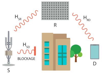
We consider the transmission of a single data stream , i.e., a sequence of signals, from a source S to a destination D via a relay R, as depicted in Fig. 1. Then, the channel matrix is combined with the beamforming vectors used at S and D, in order to obtain the Signal-to-Interference-plus-Noise Ratio (SINR) experienced at D. In particular, let be the signal transmitted from S to D, and , and be the beamforming vectors used at S, D and the I-th interferer, respectively. Moreover, we define the following matrices: is the channel matrix between the source and the destination, is the channel matrix between the I-th interferer and the destination, is the channel matrix from the I-th interferer to the relay, is the channel matrix between the source and the relay, and is the channel matrix between the relay and the destination. In a relay-free environment, the signal received at the User Equipment (UE) is computed as:
| (3) |
where represents the circularly symmetric complex Gaussian noise vector with correlation matrix , and is the signal received from the -th interferer. Accordingly, the SINR at D reads:
| (4) |
where and are the powers of the useful and the -th interfering signals, respectively.
II-B A Signal Model for the IRS
An IRS is a planar surface made of low-cost passive reflecting elements that can be programmed to alter an EM field, for example to achieve three-dimensional beamforming towards an intended destination. The working principle is similar to that of a conventional relay, the main difference being that while the latter amplifies the received signal before retransmitting it, an IRS reflects and beamforms the signal without introducing any amplification, thus saving power compared with other relaying solutions [8].
In particular, each element of the IRS acts as an antenna that captures and reflects the incoming signals, introducing a phase shift on the baseband-equivalent signal. We denote with , the reflection coefficient of the -th IRS element, where is the induced, controllable phase shift. Adopting a complex baseband notation, the signal reflected by an IRS (denoted as R), impinged with a signal originating from a source S, reads
| (5) |
where is a diagonal matrix defined as , and typically referred to as IRS configuration. Therefore, the signal received at the intended destination D (under far-field assumption with respect to the IRS) can be expressed as
| (6) |
II-C A Signal Model for the AF Relay
AF relays have been studied in the context of cooperative communications as a means to regenerate a relayed signal through amplification, with the goal of improving the system capacity. Unlike IRSs, AF relays feature a non-negligible power consumption, and introduce noise amplification.
In this work we consider as AF relay a device equipped with transmit and receive antennas. Therefore, the signal received at D is:
| (7) |
where in this case matrix also accounts for the amplification gain, and its structure depends on the specific relay design. Moreover, represents the circularly symmetric complex Gaussian noise vector with covariance matrix . Then, the power of the noise term relayed by the AF relay to receiver D and measured after the combiner at the UE, is
| (8) |
III A Full-Stack Simulator for IRS/AF Relays
Despite the availability of accurate sub-6 GHz and mmWave channel models, analytical evaluations of the 5G NR protocol stack introduce several assumptions in the system architecture, and are generally not desirable [16]. Additionally, 5G/6G cellular networks are rapidly shifting towards open and controllable network configurations, which further introduce unprecedented data-driven programmability [17]. In these regards, computer simulators are emerging as a valuable tool to let researchers better understand the performance of wireless networks, and dimension them accordingly [18].
Several simulators for 5G cellular and vehicular networks are available in the literature [14, 19, 20, 21, 22, 23, 24, 25]. However, they provide a detailed characterization of either the lower (i.e., at link-level) or the upper (i.e., at system-level) layers of the 5G NR protocol stack. Notably, the latter sacrifice PHY layer accuracy to reduce the computational complexity, but incorporate accurate models of the remainder of the protocol stack, thus enabling scalable end-to-end simulations. Despite the many software-based evaluation platforms available, to the best of our knowledge there are no end-to-end simulators for IRSs and AF relays. In [26], the authors presented an open-source module for IAB, even though it was not extended to support passive relays like IRSs. Moreover, the authors in [27] presented an ns-3 IRS module, but their work focused on vehicular networks, and did not consider the case of AF relays.
In this paper we close the gap and propose an ns-3-based simulator for IRSs and AF relays. Arguably, the main effect of the presence of these entities is the alteration of the wireless channel between the communication endpoints. Accordingly, our simulator extends the ns-3 mmwave module [14] (among the most popular 5G-oriented NR-compliant frameworks to simulate 5G networks) by implementing a new signal model for IRS and AF relays, following the characterization in Secs. II-B and II-C, respectively, which is then used to compute the SINR experienced by signals transmitted over a relayed wireless link.
III-A Implementation of the IRS/AF Signal Model
In line with [15], we assume that the transmission of the signal occurs over a frequency-selective wireless channel as 5G NR supports network operations with a bandwidth up to 400 MHz, when using FR2 [28]. Therefore, the evaluation of the SINR requires, among other things, the computation of the Power Spectral Density (PSD) of the useful component of the signal at D, i.e., , starting from that of the input signal . Additionally, we consider that both the transmitter and the receiver feature m-MIMO arrays equipped with multiple antenna elements, and use the beamforming vectors and , respectively. Under these assumptions, the input-output relationship in (3) becomes [8, 29]:
| (9) | ||||
where in turn is defined as:
where matrix is the relay matrix, i.e., a matrix which fully encodes the effect of the relay, i.e., either IRS or AF, as described in Secs. II-B and II-C for the single user case, respectively, over the wireless channel. Notably, S and D are either in Non-Line-of-Sight (NLoS) (in this case they communicate via the relay, and we consider the direct link towards D to be unavailable), or in Line-of-Sight (LoS) (in this case they do not use the relay). Accordingly, assuming that the source of interest is in NLOS with respect to its intended destination, (9) becomes:
| (10) | ||||
where and are the two disjoint sets of interferers which experience either a LoS or a NLoS channel towards D, respectively. Then, the PSD of the useful component of the signal at the receiver can be written as:
| (11) |
Based on the above definitions, our simulator computes the PSD by checking whether the communication from S to D involves a relay. If so, the PSD is computed according to the following steps.
- 1.
-
2.
Configuration of the relay and the beamforming vectors. We assume that the choice of the beamforming vectors for both S and D ( and ), as well as the relay configuration (), consist in the choice of a codeword from a pre-defined pre-computed codebook. Moreover, we assume that the devices do not have full channel knowledge, i.e., they do not know the realizations of and . Then, in line with the 5G NR beam management procedure [30], the choice of the codeword in the codebook is performed via exhaustive search, i.e., by repeatedly sending pilot signals, and measuring the SINR experienced with various configurations of the codebook. Eventually, we choose the combination of , , and yielding the highest SINR.
Notably, this procedure is not repeated at each transmission opportunity. Instead, , , and are stored and re-used for the whole channel coherence time, to mimic the actual 5G NR beam management procedure, and also reduce the complexity of the simulations. Furthermore, the evaluation of the SINR is performed by neglecting the small-scale fading terms, to further reduce the overhead. The small-scale fading will be eventually incorporated in Step 4 of the model.
-
3.
Long-term computation. Along the lines of [15], the PSD of the transmitted signal at D can be expressed as:
(12) In Eq. (12), is the equivalent channel matrix between S and D, whose generic entry is:
(13) where and are the number of multipath clusters in and , respectively. Moreover, and denote entries and of vectors and , respectively. Then, Step 3 consists in the evaluation of the long-term fading:
(14) -
4.
Small-scale fading and path loss. The small-scale fading terms are combined with the terms to compute the overall fading component of the PSD of interest:
(15) where
(16) Additionally, the path loss is computed as in (2). Since the useful signal received at D experiences two channels (from S to R, and from R to D) as a cascade, as described in (9), two path loss terms are added (in dB), to obtain the final PSD of at D as:
(17) -
5.
Interference and SINR. As the last step, we evaluate the PSDs of the interfering signals at D. To do so, we follow Steps 1–4 as for the useful component of the signal. However, the beamforming configurations are not optimized as described in Step 2. That is to say, each interferer uses the beamforming vector yielding the highest SINR towards its intended destination, while R and D employ the same configurations used in the previous steps. Finally, the SINR is evaluated as:
where is the PSD of the thermal noise at D.
III-B Integration of the IRS/AF Signal Model in the Simulator
In Sec. III-A we described how our simulator computes the channel (in terms of PSD) in case of IRS/AF relays, which is then used to calculate the end-to-end SINR at the destination D. Notice that the SINR can refer to either the SINR relative to the whole bandwidth, for narrowband signals over frequency-flat channels, or the SINR experienced over a single subcarrier, for wideband signals transmitted over frequency-selective channels. In the second case, the SINRs corresponding to the various frequency chunks are then mapped into a single SINR value, according to additional maps obtained from link-level simulations [31]. Based on that, our simulator defines a Link-to-System Mapping (L2SM), i.e., a table which associates a given SINR to a MAC-layer Transport Block (TB) error rate [32], in turn used to decide whether the TB has been correctly received or not.
The upper layers of the 5G NR protocol stack are modeled based on the ns3-mmwave module [14]. It implements a custom PHY layer supporting the NR frame structures and numerologies, and a MAC layer with ad hoc beamforming and scheduling policies. The Radio Link Control (RLC) and Packet Data Convergence Protocol (PDCP) layers implement network functions such as packet segmentation, retransmissions and/or reassembly.
IV Performance Evaluation
In this section we describe our simulation setup and parameters (Sec. IV-A), and evaluate the performance of IRSs and AF relays, considering full-stack network metrics as a function of different antenna array configurations (Sec. IV-B).
IV-A Simulation Setup
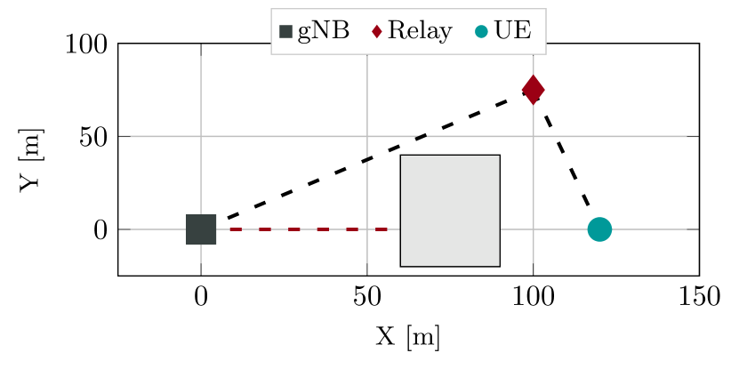
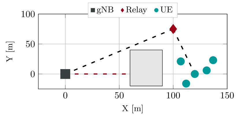
In our simulations we consider two simple yet realistic urban canyon scenarios, where we deploy a single Next Generation Node Base (gNB), UEs, with (5) in Scenario 1 (2), as illustrated in Fig. 2, and a single relay, which can be either an IRS or an AF relay. The wireless channel is modeled as an Urban Macro (UMa) link [13]. The LoS/NLoS condition depends on the geometry of the scenario. In particular, we assume that the direct wireless link between the UEs and the gNB is blocked by a building, as illustrated in Fig. 2, which introduces an additional penetration loss modeled based on [13, Sec. 7.4.3.1]. The end nodes can still communicate in LoS via the relay.
Our simulation parameters are reported in Table I. Specifically, the UEs download User Datagram Protocol (UDP) data, modeled as a constant bit-rate stream of 50 Mbps, from a remote server. We assume that, at each transmission opportunity towards the generic -th UE, both AF and IRS relays can use their optimal configuration, i.e., the codeword yielding the highest end-to-end SINR towards UE . The system operates at 28 GHz, with a total bandwidth of 100 MHz, to be shared among all the devices in Time Division Multiple Access (TDMA). The gNB is equipped with an antenna array of 64 elements, and uses a power of 33 dBm. For the IRS, we consider a number of reflecting elements from 200 to 7 200. For the AF relay, we consider antenna arrays from 16 to 256 elements.
| Parameter | Value |
|---|---|
| Carrier frequency | 28 GHz |
| Total bandwidth | 100 MHz |
| Number of UEs () | {1, 5} |
| gNB antenna array | HV |
| gNB max RF power | 33 dBm |
| UE antenna array | HV |
| IRS antenna array | {HV, HV,HV, HV} |
| AF antenna array | {H V, H V, H V} |
| AF amplification | 40 dB |
| Antenna radiation pattern | [13, Table 7.3-1] |
| UDP source rate | 50 Mbps |
IV-B Numerical Results
We now compare the end-to-end performance of IRS- and AF-relay assisted networks in terms of:
-
•
SINR. It is a measure of the quality of the channel. It depends on PHY-layer characteristics, including the relative distance between the transmitter, the receiver and the relay (if applicable), the operating frequency, the propagation conditions, and the channel bandwidth.
-
•
End-to-end throughput. It is measured as the total number of received bytes per user divided by the total simulation time.
-
•
End-to-end latency. It is measured from the time each packet is generated at the application layer to when it is successfully received. Accordingly, it accounts for both transmission and queuing times.
-
•
Packet Error Rate (PER). It is measured as the ratio between the number of packets delivered with errors and the total number of transmitted packets.
The IRS/AF performance will be evaluated against a baseline scenario (referred to as “gNB-only”) in which there is no intermediate relay.
SINR
Our analysis starts with the SINR statistics depicted in Fig. 3, relative to Scenario 1 with . First, in Fig. 3(a) we observe that the presence of the relay improves the SINR (on average up to dB) compared to the “gNB only” baseline, in which the UE communicates in NLoS. Notably, as depicted in Fig. 3(b), both IRS and AF relays provide an end-to-end SINR gain which scales proportionally with respect to the number of radiating elements at the relay. For the IRS, this effect is given by the beamforming gain, as well as by the fact that the power collected by the IRS is proportional to its surface area, which in turn is proportional to the number of radiating elements [33].
The AF-assisted configurations always outperform the IRS-assisted ones in terms of SINR (on average up to dB, with the same number of antennas): this is expected since the AF relay amplifies the signal, thus achieving a higher end-to-end gain. Notice that the SINR is below 0 dB when the IRS is made of less that elements, which justifies the use of very large IRS panels. Indeed, an IRS panel of elements provides an average SINR of dB, which is enough to support reliable transmissions as long as communication requirements are not too extreme, as we will demonstrate in the following paragraphs.
End-to-end throughput
In Fig. 4 we plot the end-to-end throughput experienced at the application layer, thus considering the impact of the whole 5G NR protocol stack. When (Scenario 1) the average throughput is an indication of the ergodic capacity. We see that the throughput for the “gNB only” baseline is zero, given the very low SINR (below the sensitivity threshold of most commercial receivers) experienced at the physical layer. Interestingly, even though the AF relay with antennas guarantees, on average, 15 dB higher SINR than an IRS with elements (from Fig. 3(a)), we see that the end-to-end throughput of the two configurations is comparable. This demonstrates that, in a simple scenario with only one UE, an average SINR of 15 dB is enough to satisfy all traffic requests. In this case, the IRS is more desirable than an AF relay given its simplicity. Also, it is not convenient to further increase the IRS size, given that the throughput is already maximized and equal to the UDP source rate (50 Mbps in our simulations).
When (Scenario 2) the average per-UE throughput decreases significantly with respect to Scenario 1 due to the fact that, in a multi-user scenario, radio resources must be shared among UEs, which may lead to channel congestion. This result validates the accuracy and realism of our ns-3 framework. Nevertheless, this effect is less pronounced for very large antenna panels. For example, for an AF relay of antennas, the per-UE throughput drops by almost , while considering an array of elements the per-UE throughput decreases by only . Even in Scenario 2, AF-assisted networks can still sustain the application source rate, as long as at least antennas are used. On the other hand, IRSs are constrained by the limited SINR available at the PHY layer, and are never able to achieve the full source rate offered by the application. The maximum achievable throughput is around Mbps for elements, i.e., % compared to the case of .
End-to-end latency
Finally, in Fig. 5 we plot the 95-th percentile of the end-to-end latency experienced at the application layer. We can see that the performance is generally poor even in the simple scenario in which only one UE is deployed (Scenario 1), where the latency is higher than ms for most relay configurations, suggesting that in these cases the system is unstable. In fact, the use of relays featuring small antenna panels results in very high levels of queuing and buffering, which leads to latency degradation. This issue can be solved by configuring larger IRS and AF relays, despite the increased system complexity. For example, an IRS of elements and an AF relay with elements can guarantee an end-to-end latency lower than ms, that is in line with most 5G application requirements. Notice that the latency for the “gNB only” configuration is not particularly representative, as it is relative to only the correctly received packets. In fact, without the relay, transmissions are in NLoS and result in several packet losses (see the PER in Fig. 6), which makes the system less congested; the (few) packets that make it to the application layer are then transmitted with lower delay. Nevertheless, the latency is still more than two orders of magnitude higher than considering the best IRS and AF configurations, an indication that relays are desirable in these types of networks.
When (Scenario 2), the latency is generally higher compared to when . This is expected since UEs are competing for the available resources. In addition, using UDP as transport protocol, thus with a full buffer source traffic model, each end-to-end flow does not self-regulate to the actual network conditions, thus congestion arises. Better performance could be achieved considering non-UDP traffic: for example, the congestion control mechanism available in Transmission Control Protocol (TCP) would regulate the source traffic, and prevent network congestion and buffer overflow.
Notice that, even considering the most aggressive IRS architecture with elements, the latency is on average above ms, vs. ms in Scenario 1. This is due to the fact that, in this scenario, more than 20% of the packets are lost and retransmitted (see Fig. 6), which increases the packet delay. For an AF relay with antennas, instead, the latency is more than times lower and equal to around ms on average, with a PER as low as 3%, which can still support some key target communication requirements. We can conclude that IRS-assisted networks, despite consuming less power, are not appropriate in this scenario, unless very large IRS panels are used.
V Conclusions and Future Work
IRSs and AF relays are amongst the most promising technologies to facilitate 6G networks. Not only can these elements improve both communication and coverage of wireless devices, but also promote lower energy consumption compared to IAB systems. In this paper we proposed a signal model for IRSs and AF relays, based on the 3GPP TR 38.901 channel for 5G NR networks, and explained the methodology we used to perform network-level simulations of 5G scenarios with IRS and AF relay nodes. Based on this framework, we performed simulations to provide numerical guidelines to dimension IRS/AF-assisted networks. In particular we obtained that:
-
•
Both IRS and AF relays can improve the throughput, latency and PER of end users compared to a baseline scenario in which relays are not deployed.
-
•
IRSs are valid solutions in small networks, and more desirable technologies than AF relays given their inherent simplicity and power efficiency.
-
•
AF relay are more appropriate in dense networks, while IRSs should be large, despite the increased system complexity, to satisfy the typical communication requirements.
As part of our future research we will further extend our network simulator to consider more sophisticated/advanced scenarios, for example in which heterogeneous types of relays are deployed, and compare the numerical performance of IRS/AF relays with that of IAB.
Acknowledgment
The work of Amir Ashtari Gargari received support by the European Commission through the EU MSCA ITN Program (grant no. 861222).
References
- [1] 3GPP, “NR and NG-RAN overall description,” TS 38.300, 2018.
- [2] S. Rangan, T. S. Rappaport, and E. Erkip, “Millimeter-wave cellular wireless networks: Potentials and challenges,” Proceedings of the IEEE, vol. 102, no. 3, pp. 366–385, Mar. 2014.
- [3] D. López-Pérez, M. Ding, H. Claussen, and A. H. Jafari, “Towards 1 Gbps/UE in cellular systems: Understanding ultra-dense small cell deployments,” IEEE Communications Surveys & Tutorials, vol. 17, no. 4, pp. 2078–2101, 2015.
- [4] 3GPP, “NR; Study on integrated access and backhaul,” TR 38.874, 2018.
- [5] M. Polese, M. Giordani, T. Zugno, A. Roy, S. Goyal, D. Castor, and M. Zorzi, “Integrated Access and Backhaul in 5G mmWave Networks: Potential and Challenges,” IEEE Communications Magazine, vol. 58, no. 3, pp. 62–68, March 2020.
- [6] A. Chaoub, M. Giordani, B. Lall, V. Bhatia, A. Kliks, L. Mendes, K. Rabie, H. Saarnisaari, A. Singhal, N. Zhang, S. Dixit, and M. Zorzi, “6G for Bridging the Digital Divide: Wireless Connectivity to Remote Areas,” IEEE Wireless Communications [Early Access], 2021.
- [7] R. Flamini, D. De Donno, J. Gambini, F. Giuppi, C. Mazzucco, A. Milani, and L. Resteghini, “Towards a Heterogeneous Smart Electromagnetic Environment for Millimeter-Wave Communications: An Industrial Viewpoint,” IEEE Transactions on Antennas and Propagation, 2022, doi: 10.1109/TAP.2022.3151978.
- [8] E. Björnson, Ö. Özdogan, and E. G. Larsson, “Intelligent reflecting surface versus decode-and-forward: How large surfaces are needed to beat relaying?” IEEE Wireless Communications Letters, vol. 9, no. 2, pp. 244–248, Oct 2019.
- [9] C. Huang, A. Zappone, G. C. Alexandropoulos, M. Debbah, and C. Yuen, “Reconfigurable intelligent surfaces for energy efficiency in wireless communication,” IEEE Transactions on Wireless Communications, vol. 18, no. 8, pp. 4157–4170, Jun 2019.
- [10] Q. Wu and R. Zhang, “Intelligent reflecting surface enhanced wireless network: Joint active and passive beamforming design,” in IEEE Global Communications Conference (GLOBECOM). IEEE, 2018.
- [11] E. Basar and I. Yildirim, “Simris channel simulator for reconfigurable intelligent surface-empowered communication systems,” in IEEE Latin-American Conference on Communications (LATINCOM), 2020.
- [12] The ns-3 network simulator. [Online]. Available: https://www.nsnam.org
- [13] 3GPP, “Study on channel model for frequencies from 0.5 to 100 GHz,” 3rd Generation Partnership Project (3GPP), Technical Report (TR) 38.901, Jun. 2018, version 15.0.0.
- [14] M. Mezzavilla, M. Zhang, M. Polese, R. Ford, S. Dutta, S. Rangan, and M. Zorzi, “End-to-end simulation of 5G mmWave networks,” IEEE Commun. Surveys Tuts, vol. 20, no. 3, pp. 2237–2263, 2018.
- [15] T. Zugno, M. Polese, N. Patriciello, B. Bojović, S. Lagen, and M. Zorzi, “Implementation of a Spatial Channel Model for ns-3,” in Proceedings of the 2020 Workshop on ns-3, 2020, p. 49–56.
- [16] P. K. Gkonis, P. T. Trakadas, and D. I. Kaklamani, “A Comprehensive Study on Simulation Techniques for 5G Networks: State of the Art Results, Analysis, and Future Challenges,” Electronics, vol. 9, no. 3, p. 468, Mar 2020.
- [17] L. Bonati, M. Polese, S. D’Oro, S. Basagni, and T. Melodia, “Open, programmable, and virtualized 5G networks: State-of-the-art and the road ahead,” Computer Networks, vol. 182, p. 107516, Dec 2020.
- [18] F. Wilhelmi, M. Carrascosa, C. Cano, A. Jonsson, V. Ram, and B. Bellalta, “Usage of network simulators in machine-learning-assisted 5G/6G networks,” IEEE Wireless Communications, vol. 28, no. 1, pp. 160–166, Feb 2021.
- [19] S. Choi, J. Song, J. Kim, S. Lim, S. Choi, T. T. Kwon, and S. Bahk, “5G K-SimNet: End-to-end performance evaluation of 5G cellular systems,” in 2019 16th IEEE Annual Consumer Communications & Networking Conference (CCNC). IEEE, 2019, pp. 1–6.
- [20] G. Nardini, D. Sabella, G. Stea, P. Thakkar, and A. Virdis, “Simu5G–An OMNeT++ Library for End-to-End Performance Evaluation of 5G Networks,” IEEE Access, vol. 8, pp. 181 176–181 191, 2020.
- [21] N. Patriciello, S. Lagen, B. Bojovic, and L. Giupponi, “An E2E simulator for 5G NR networks,” Simulation Modelling Practice and Theory, vol. 96, p. 101933, Nov 2019.
- [22] S. Pratschner, B. Tahir, L. Marijanovic, M. Mussbah, K. Kirev, R. Nissel, S. Schwarz, and M. Rupp, “Versatile mobile communications simulation: The Vienna 5G link level simulator,” EURASIP Journal on Wireless Communications and Networking, vol. 2018, no. 1, pp. 1–17, Sep 2018.
- [23] M. K. Müller, F. Ademaj, T. Dittrich, A. Fastenbauer, B. R. Elbal, A. Nabavi, L. Nagel, S. Schwarz, and M. Rupp, “Flexible multi-node simulation of cellular mobile communications: the Vienna 5G System Level Simulator,” EURASIP Journal on Wireless Communications and Networking, vol. 2018, no. 1, September 2018.
- [24] C.-K. Jao, C.-Y. Wang, T.-Y. Yeh, C.-C. Tsai, L.-C. Lo, J.-H. Chen, W.-C. Pao, and W.-H. Sheen, “WiSE: a system-level simulator for 5G mobile networks,” IEEE Wireless Communications, vol. 25, no. 2, pp. 4–7, Apr 2018.
- [25] M. Drago, T. Zugno, M. Polese, M. Giordani, and M. Zorzi, “MilliCar: An ns-3 Module for MmWave NR V2X Networks,” in Proceedings of the 2020 Workshop on ns-3, Gaithersburg, MD, USA, Jun. 2020.
- [26] M. Polese, M. Giordani, A. Roy, S. Goyal, D. Castor, and M. Zorzi, “End-to-end simulation of integrated access and backhaul at mmWaves,” in IEEE 23rd International Workshop on Computer Aided Modeling and Design of Communication Links and Networks (CAMAD). IEEE, 2018.
- [27] K. Heimann, B. Sliwa, M. Patchou, and C. Wietfeld, “Modeling and Simulation of Reconfigurable Intelligent Surfaces for Hybrid Aerial and Ground-Based Vehicular Communications,” 24th International ACM Conference on Modeling, Analysis and Simulation of Wireless and Mobile Systems, 2021.
- [28] 3GPP, “NR - user equipment (ue) radio transmission and reception; part 1: Range 1 standalone - Rel. 16,” TS 38.101-1, 2020.
- [29] Q. Wu and R. Zhang, “Intelligent reflecting surface enhanced wireless network via joint active and passive beamforming,” IEEE Transactions on Wireless Communications, vol. 18, no. 11, pp. 5394–5409, Aug 2019.
- [30] M. Giordani, M. Polese, A. Roy, D. Castor, and M. Zorzi, “A tutorial on beam management for 3GPP NR at mmWave frequencies,” IEEE Commun. Surveys Tuts, vol. 21, no. 1, pp. 173–196, Firstquarter 2019.
- [31] S. Lagen, K. Wanuga, H. Elkotby, S. Goyal, N. Patriciello, and L. Giupponi, “New radio physical layer abstraction for system-level simulations of 5G networks,” in IEEE International Conference on Communications (ICC), 2020.
- [32] M. Mezzavilla, M. Miozzo, M. Rossi, N. Baldo, and M. Zorzi, “A lightweight and accurate link abstraction model for the simulation of LTE networks in ns-3,” in Proceedings of the 15th ACM international conference on Modeling, analysis and simulation of wireless and mobile systems, 2012, pp. 55–60.
- [33] E. Björnson, Ö. Özdogan, and E. G. Larsson, “Reconfigurable intelligent surfaces: Three myths and two critical questions,” IEEE Communications Magazine, vol. 58, no. 12, pp. 90–96, 2020.