scaletikzpicturetowidth[1]\BODY
Unfreezing Social Navigation: Dynamical Systems based Compliance for Contact Control in Robot Navigation
Abstract
Large efforts have focused on ensuring that the controllers for mobile service robots follow proxemics and other social rules to ensure both safe and socially acceptable distance to pedestrians. Nonetheless, involuntary contact may be unavoidable when the robot travels in crowded areas or when encountering adversarial pedestrians. Freezing the robot in response to contact might be detrimental to bystanders’ safety and prevents it from achieving its task. Unavoidable contacts must hence be controlled to ensure the safe and smooth travelling of robots in pedestrian alleys. We present a force-limited and obstacle avoidance controller integrated into a time-invariant dynamical system (DS) in a closed-loop force controller that let the robot react instantaneously to contact or to the sudden appearance of pedestrians. Mitigating the risk of collision is done by modulating the velocity commands upon detecting a contact and by absorbing part of the contact force through active compliant control when the robot bumps inadvertently against a pedestrian. We evaluated our method with a personal mobility robot -Qolo- showing contact mitigation with passive and active compliance. We showed the robot able to overcome an adversarial pedestrian within 9 N of the set limit contact force for speeds under 1 m/s. Moreover, we evaluated integrated obstacle avoidance proving the ability to advance without incurring any other collision.
Index Terms:
Mobile Service Robots, Human-Robot Interaction, Force control, Compliance and Impedance ControlI Introduction
As a consequence of the widespread diffusion of mobile robots in public environments, the chances that robots and bystanders may collide will increase. Looking at the statistics in the automotive sector, the number of crashes involving pedestrians is a considerable portion of the total number of accidents [1]. Real-life implementations of any obstacle avoidance are limited by the reactivity of the robot i.e. kinematic and dynamic constraints, actuation power, and highly limited computational resources on mobile robots. Robots cannot behave like pedestrians. Most of the service robots are non-holonomic and cannot step on the side. They are also less reactive and lacks the means to communicate their intended move in easily interpretable ways, and are rarely knowledgeable of proxemics and other social rules [2]. Nonetheless, the utility of mobile service robots is getting traction and valuable services such as in-hospital assistance, last-mile deliveries (Starship Inc. USA), autonomous cleaning robots (Bluebotics, Switzerland) and autonomous wheelchairs (Whill Inc. Japan) are becoming popular.
Similarly to what happened with industrial collaborative robots [3, 4], chances are high that deployment will proceed and that society will slowly accept and allow physical contact between mobile robots and humans, especially in crowded environments [5]. Hence, there is some urgency to develop control approaches and design requirements to mitigate risks and allow motion control in post-contact between a pedestrian and a service robot.
Most attention has been given to pre-collision planning [4, 6] and human motion prediction [7, 8]. As far as physical collisions between humans and robots are concerned, efforts were solely directed at evaluating collisions with collaborative robot arm manipulators [9, 3, 10]. These works were instrumental and led to the ISO 15066:2016 [11] standard that establishes values for pain thresholds for blunt impacts with respect to force and pressure, after collisions with a robotic arm for determining what should be its operational velocity around humans. However, there is no equivalent standard for collision with light-weight vehicles [12].
Mutual anticipation remains critical in ensuring that humans can navigate safely in crowded environments [13]. Nonetheless, pedestrians’ expectations of robots’ motion capabilities may exceed robots’ actual motion constraints, thereby increasing the risk of misinterpreted reciprocal avoidance. Currently, the basic safety control system let the robot freeze as soon as it perceives a contact [14], a reaction that would most likely be unexpected by pedestrians and lead to more dangerous collisions with pedestrians stumbling on the robot. This may be particularly the case, considering that collisions would occur within highly dynamic environments such as malls, airports, hospitals, markets, or mix-traffic areas where pedestrians, mobility devices, and even vehicles are frequent. Herewith, making a ”frozen” robot a danger to itself and bystanders [15]. In this work, we investigate a possible less dangerous and better accepted post-collision reaction that avoids the ”freezing” robot problem.
We extend our dynamical systems (DS) based obstacle avoidance controller [16], by augmenting it with a compliant control mechanism, using a passive DS approached offered in [17]. Assuming that we have real-time contact sensing in closed-loop control, we enable impedance control for our mobile robot through estimated contact forces over a known hull, following our previous approach for explicit force modulation for collaborative robot environments developed in [18]. Unlike previous works on DS-based compliance, in our formulation the obstacle’s exact shape and contact location are unknown. Thus, we simplify the problem by assuming a single contact point and use the only information at our disposal, namely the hull shape of the robot, for controlling the desired force during the interaction.
A similar principle for closed-loop force control with 6-axes Force/Torque was offered in [19] with a focus on learning touch commands on a stiff hull. While the method in [20] offered an impedance control response when guiding a person’s motion while limiting the maximum guidance force. Our control approach offers the reactivity of time-invariant DS combined with contact estimations of impacts through a compliant bumper, herewith ensuring impact absorption through passive and active compliance for mitigating unexpected impacts with mobile robots.
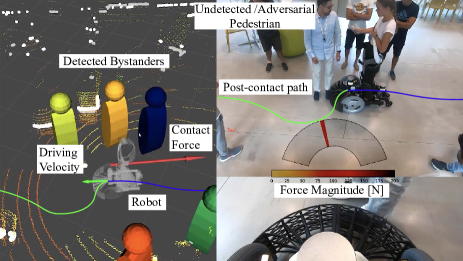
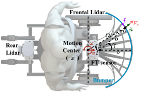
We validate the method on the semi-autonomous standing mobility vehicle Qolo [21, 22] shown in Fig. 1; a type of powered wheelchair for standing mobility of lower-limb impaired people, similar to powered scooters, hoverboards, and unicycles, currently widespread. We tested the approach to validate performance at mitigating contact forces by generating multiple collisions with a static obstacle varying the speed at contact. We show that the robot could successfully slide against the obstacle without exceeding the limit on contact force. Although current implementation relies on the assumption of single contact, this could be extended with higher sensing resolution such as multi-contact sensing in mobile manipulators through artificial skin [23], or through other sensing methods [24]. The source code and simulations with other robot types is available at: https://github.com/epfl-lasa/sliding-ds-control [25].
II Problem Statement
In this formulation for post-collision control, we assumed:
-
1.
Knowledge of the expected contact surface, namely a convex human body part.
-
2.
A collision could occur unexpectedly, thus, distance to the obstacle is unknown a priori.
-
3.
Expected contact occurs at a single location per sensing surface.
-
4.
The operational speed of the robot is slow enough to be safe in the transient phase thus, controllable post-collision.
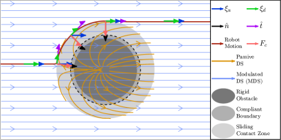
In Fig. 2 we depicted a linear-DS with the robot represented as a holonomic point-mass (any point in this Cartesian space) and the pedestrian in contact as a convex shape. There are two zones of contact with the obstacle represented by: first, a physically impenetrable obstacle (dark grey), and second, a deformable region of the obstacle with a compliant boundary (dotted line) which allows controlling for safe contact force. Finally, we mark a sliding zone (lighter-grey) that represents the volume occupied by the robot during contact around the obstacle. The resulting behaviour of the system is a force bounded sliding contact around the obstacle after entering in contact with the compliant boundary, assuming that there will be a state where the modulated DS will lead away from the contact surface without colliding with other obstacles.
Controller Formulation
In order to derive the motion controller, we modelled the robot dynamics as: , where represents the robot’s Cartesian velocity as a time invariant position dependent dynamical system. corresponds to the virtual mass of the robot, accounts for centrifugal and Coriolis terms, represents the control forces and any external disturbances to be rejected. An impedance-DS is used to achieve a sliding motion for overcoming the obstacle. We design a nominal trajectory controlling for the robot’s speed and generated through a function . We then control for the torques using a damped tracking controller over ,
| (1) |
where represents a negative defined damping effect. is the dynamical system effectively controlling the robot during contact, composed as: , where represents the driving force generated by the nominal DS input tangential to the collision surface which can be transformed into the contact dynamics as:
| (2) |
where accounts for a discretizing time constant. describes the force control function as:
| (3) |
where was chosen a contact force limit bounded by safety and acceptability, while represents the measured contact force. Yielding a controller of the form:
| (4) |
The damping effect on the matrix was controlled by a normal and tangential parameters over the surface of the obstacle, and , respectively.
| (5) |
where was defined by the contact location normal. The parameter allow to control the behaviour around the surface, for instance by setting we can provide an undamped free motion along the tangential direction of the collision surface.
Finally, transformation to the velocity domain of the robot was done by a first order Taylor expansion, thus the control for a desired velocity can be written as,
| (6) |
Releasing contact:
Equation 6 allows the robot to slide over the obstacle while limiting a constant contact force (), but it does not allow the robot to move away from the obstacle. Thus, we defined an additional term in (6) () when the normal vector and underlying dynamical system desired motion oppose each other. Herewith, enabling the robot to move away from the obstacle if the DS indicates a feasible free-motion space.
Then, the final controller is defined as:
| (9) |
Velocity magnitude
When required by the robot application, the driving underlying DS magnitude could be upper bounded by , hereby, guaranteeing a controllable speed allowed during contact interaction around the obstacle.
Moving target
In case of a traceable moving obstacle in contact, we can include such estimation of the obstacle’s motion to the previous formulation by defining the robot’s state relative to the obstacle’s pose (). This effectively makes the desired motion dependent on the obstacle’s response. The DS, hence, speeds up or slows down according to the obstacle’s speed while controlling the desired contact force. Such behaviour requires explicit velocity estimation of the obstacle in contact. This estimate could be local, using, for instance, optical flow from a fish-eye camera or laser-based tracker of objects in close vicinity. While this requires the placement of more sensors, such as sensors scanning space on the side of the robot, this could enhance fluidity social navigation in interactions with a crowd flow or other dynamic obstacles.
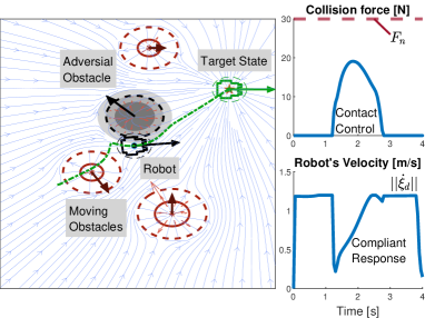
Fig. 3 depicts a linear-DS towards an attractor (green mark) modulated by the surrounding moving obstacles. An example of a mobile robot navigation in 2D. The resulting DS acts as the input to the proposed compliant modulation when an ”adversarial” obstacle (invisible to the modulation) gets in contact (sensed by penetration and simulated with a constant mass-spring system), which triggers the compliant controller and enables a sliding behaviour around it while avoiding all other moving obstacles.
III Control architecture and Sliding surface
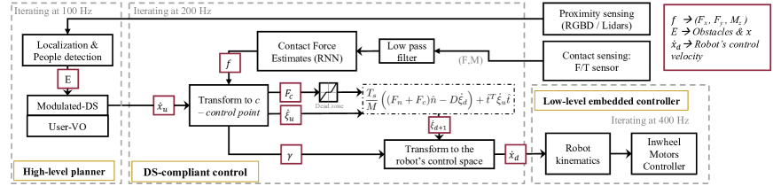
We based the robot’s control architecture on a continuous controller that handles three states of the mobile robot, namely: obstacle avoidance, contact, and post-collision control. Fig. 4 describes the general controller in three stages. First a high-level closed-loop motion planner drives the dynamics of the robot in its control space (). While we used a modulated DS [16] for obstacle avoidance, any other velocity-based planners could be used here, e.g, in the case of velocity obstacles (VO) based obstacle avoidance through the formulation in [26]. Second, control of compliance and contact force through sliding method using a known sensing surface over the robot’s hull with a limited contact force . Ensuring that the robot reacts to unexpected contacts and advances with a sliding manoeuvre should the underlying obstacle avoidance lead away from the contact surface without colliding with other obstacles. Third, a low-level controller that handles the execution in real-time closed-loop control.
III-A Control Point over the Robot’s Surface
To execute the control in a mobile robot we need to include a transformation between the robot’s control space and a control point () around the bumper shape by using the estimated collision location over the bumper surface at an angle . Which was estimated as from the center of the bumper (see Fig. 5).
Thus, we control the effective velocity () at the point of collision perpendicular to the bumper surface by transforming it to the control space of the robot.
The surface at the control point can be described using the normal () and tangential () unit vectors,
| (10) | |||||
| (11) |
Then, we can define a Jacobian matrix () to transform the motion at center of the robot (in the case of Qolo, a non-holonomic differential wheel system) to an effective velocity () at the control point on the surface in contact (holonomic):
With a known hull surface (see Fig. 5) described as,
| (13) | |||||
| (14) |
With the system controlled in the velocity space of the robot we map the DS through the following:
| (15) |
where, and are the desired linear and angular velocities defined by the high level planner resp.
Finally, we transform back to the robot’s control space () through the inverse of the Jacobian.
III-B Non-linear compliance compensation
The impact absorbing bumper (see Fig. 5) was designed as a compliant surface light-weighted () in ABS material, mounted on a 6 axis force/torque (FT) sensor (Botasys Rokubi 2.0) at the centre of the semi-circular bumper. The bumper was mounted through a padding material to the hard surface of the robot frame with spring-loaded screws at each side of the mount, thus, releasing part of the weight to the main frame of the robot. Herewith, mitigating the impact during the transient phase. Unlike the work in [19] where a stiff hull was developed mounted on an FT sensor. However, this brings a challenge in accurately estimating contacts on the surface of the hull, which we have tackled by learning the non-linearity of the passive-compliance through data of known impact forces.
To remove the effects of the non-rigidity of the bumper (see Fig. 5), a prediction model was developed through 2 methods, first with a support vector regression (SVR), and secondly with a recurrent neural network (RNN), where we chose the second in implementation.
We trained the models with a known force applied to the bumper at various locations through an second FT sensor impacting the bumper surface. Then, the effective force and moment at the onboard FT sensor were estimated assuming a rigid model of the bumper. The non-linear model was trained over the measured FT values from the onboard sensor to find , , and . We use three independent models to get corrections over , and .
Assumptions: First, other components of the forces (, and ) are significantly smaller thus can be neglected. Second, the model removes all non-rigidity effects from the sensor measurements, herewith, we can consider the bumper as a rigid body on the robot’s structure. Third, we only account for pure forces applied at the point of contact.
The calibration dataset consisted of slow and fast force variations on the bumper at various force magnitudes, impulse responses at various force magnitudes, and pulls on the bumper to cancel any undesired behaviour. The dataset was generated by applying a known force (using a FT sensor) on a grid on the bumper. For each type of force profile, 3 samples of of impacts were recorded at at each point on the grid. Further details of the data and implementation of SVR and RNN are available in the online repository [25].
Contact force estimation comparison SVR vs. RNN
The calibration dataset is divided into split with part for training and part for validation. In this paper, on one hand, a -SVR [27] was trained over the training dataset resulting in approximately support vectors for each axis. On the other hand, for the RNN, a single LSTM layer with a buffer of 6 samples was implemented. The output of the LSTM layer was then fed to a neural net for each of the desired force. Because of the lower estimation error () and fastest processing time (), we choose the RNN for real-time usage in the robot (as shown in table I).
| SVR | RNN | ||
| Training Performance | [] | ||
| [] | |||
| [] | |||
| Testing Performance | [] | ||
| [] | |||
| [] | |||
| On-board Computation Time [] | |||
III-C Contact location estimation
We estimated the collision angle from the reference coordinate system at the sensor from , , and , as . Note that and at the point of contact and the sensor are assumed the same as described above. By replacing and by and respectively, we get eq. 16. Eq. 17 describes explicitly the by solving the quadratic equation in .
| (16) | |||||
| (17) |
Finally, the force magnitude can be estimated as .
IV Experimental Evaluation
For evaluation in combination with obstacle avoidance in close to real-life expected situations, we equipped the robot Qolo [22] with 2 Lidars (Velodyne VLP-16), and an RGBD sensor (Intel Realsense). Obstacle’s tracking was performed through real-time people detection implemented through a pipeline of sensing fusion of Lidar-based detection by DR-SPAAM [28] and RGBD detection through YOLO [29]. The full controller repository can be found here: Qolo-ROS [30]. The control parameters were set as follows, he discretizing time constant () to the sampling time of the control loop () for real-time controller dynamics. The virtual robot mass () was set to for light-behaviour. Damping parameters and were set to and respectively to allow undamped tangential motion and partially damped normal motion of the collision surface.
IV-A Contact Control Evaluation at Multiple Speeds
First, we evaluated the effects of increasing the operational speed of the robot on the post-collision force response with the proposed controller, to understand the effect of the approach for real-life contact situations. We run five sets of collisions per condition between the mobile robot Qolo () and a static person (). The contact force limit for compliance was set to (well below the average pain threshold for the lower legs [11]). While the desired motion () was set to a linear-DS (ignoring the obstacle) towards an attractor at ahead of the robot.
The tests were conducted at four operational speeds of , by setting the robot to approach the person (only the authors) frontally and about of the line of motion, thus impacting the bumper at . The post-contact speed magnitude was set to .
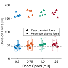
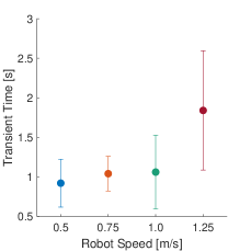
We observed a peak collision force over in most cases, as expected for the transient phase (see, Fig. 6(a)), given the overall delay of the control system (passive-compliance is needed for absorbing part of the impact). The mean collision force was for speeds up to , and for the highest speed of . All contact forces during sliding were well within the desired limit of ( of the pain threshold). Results are summarized in table II. The mean transient phase time (time to stabilise the compliance control) showed a difference between impacts below with , while for impacts at presented a slower response of (see, Fig. 6(b)). Further control parameter settings are detailed in the supplementary repository [25].
IV-B Evaluation with Integrated Obstacle Avoidance

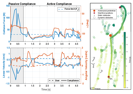
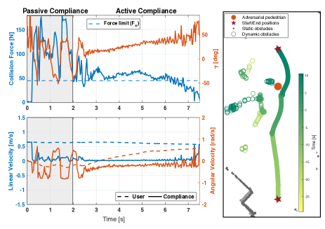
We further tested the approach in autonomous driving mode and contrasted two obstacle avoidance methods: first modulated obstacles DS from [16] and second, a variant on the Velocity-obstacle (VO) that solves operator given commands with the known shape of the robot [26]. We recorded three tests per method with a safe operational velocity () and sliding velocity (). Results in Fig. 7(a) shows an illustration of the experimental scenario, where an adversarial pedestrian jumps in front of the robot from behind another pedestrian faster than the physical limits of the robot’s actuation, thus producing a collision. In both examples (see Fig. 7(b)-7(c)) there is the first stage of transient impact (left figure, shaded area) beyond any control on the robot (passive-compliance is needed for absorbing part of the impact). Subsequently, the compliant controller limits the contact interaction (active compliance phase) to the set force value (), while performing the sliding motion around the obstacle as long as there is no other pedestrian on its path.
| Mean Force [] | Std. Deviation [] | ||
| Robot Speed [̇] | |||
| Control Type | VO control | ||
| MDS Control |
Results showed performance of contact force error of , and for MDS and VO modes resp. (see, table II). In VO mode (with an operator on-board) the heavier robot was more controllable, achieving a smaller error in comparison with MDS mode. Results of the trajectory response showed in VO mode that the user was able to overcome the adversarial pedestrian by drifting away quicker from contact, thus trajectories deviated further from the linear path (see, Fig. 7(b) right side). In contrast, the MDS control made longer contact with the obstacle, moving around it, thus the overall trajectories were closer to the original linear DS (see, Fig. 7(c) right side).
V Summary and Discussion
We have presented a control method for a mobile service robot to achieve a reactive control on post-collision which allows to absorb part of the impact and continue moving by sliding around the pedestrian. Herewith, proposing an alternative solution to the common ”safe” approach of freezing a robot upon contact.
The experimental assessment at multiple operational speeds allowed us to illustrate the approach in real-life operations. In the case of the robot Qolo, we found the current control system capable of recovering from an unexpected collision within of the impact when driving below , and navigating around the unforeseen obstacle.
The results with integrated obstacle avoidance showed a robot able to overcome a pedestrian in both tested methods, namely, modulated dynamical systems (DS) and velocity obstacles (VO). In both cases without incurring further contact with bystanders, and within desired limits of ”safe” contact force. Among the two methods, a smoother trajectory was achieved in DS controlled motions, whereas user-driven VO tests showed lower contact forces. A likely result of the user decision of drifting away quicker from contact, which in turn resulted in a larger deviation from the initial trajectory.
Future work should look more closely at how to handle multiple contacts. As well, investigate how pedestrian responses to contact and its effect to the robot planner for social acceptability and safety.
Acknowledgement
This work was funded by the EU H2020 project ”Crowdbot” (779942). The experiments were approved with an ethical protocol by the human research ethical committee of EPFL (Approval No: HREC-032-2019). We thank K. Suzuki and the University of Tsukuba for lending the robot Qolo used in this experiment. Disclaimer: DP holds a patent of the robot Qolo and shares in the company Qolo Inc.
References
- [1] J. Anderson, N. Kalra, K. Stanley, P. Sorensen, C. Samaras, and O. Oluwatola, Autonomous Vehicle Technology: A Guide for Policymakers, 1st ed. Santa Monica, Calif.: RAND Corporation, 2016.
- [2] K. Charalampous, I. Kostavelis, and A. Gasteratos, “Recent trends in social aware robot navigation: A survey,” Robotics and Autonomous Systems, vol. 93, pp. 85–104, 2017. [Online]. Available: http://dx.doi.org/10.1016/j.robot.2017.03.002
- [3] M. J. Rosenstrauch and J. Kruger, “Safe human-robot-collaboration-introduction and experiment using iso/ts 15066,” in 2017 3rd International Conference on Control, Automation and Robotics (ICCAR), 2017, pp. 740–744.
- [4] S. Haddadin, A. De Luca, and A. Albu-Schäffer, “Robot collisions: A survey on detection, isolation, and identification,” IEEE Transactions on Robotics, vol. 33, no. 6, pp. 1292–1312, 2017.
- [5] M. C. Shrestha, Y. Nohisa, A. Schmitz, S. Hayakawa, E. Uno, Y. Yokoyama, H. Yanagawa, K. Or, and S. Sugano, “Using contact-based inducement for efficient navigation in a congested environment,” in 2015 24th IEEE International Symposium on Robot and Human Interactive Communication (RO-MAN), Aug 2015, pp. 456–461.
- [6] A. Bajcsy, S. Bansal, E. Ratner, C. J. Tomlin, and A. D. Dragan, “A Robust Control Framework for Human Motion Prediction,” IEEE Robotics and Automation Letters, vol. 6, no. 1, pp. 24–31, 2021.
- [7] Y. Kobayashi, T. Sugimoto, K. Tanaka, Y. Shimomura, F. J. Arjonilla Garcia, C. H. Kim, H. Yabushita, and T. Toda, “Robot Navigation Based on Predicting of Human Interaction and its Reproducible Evaluation in a Densely Crowded Environment,” International Journal of Social Robotics, 2021. [Online]. Available: https://doi.org/10.1007/s12369-021-00791-9
- [8] D. Fridovich-Keil, A. Bajcsy, J. F. Fisac, S. L. Herbert, S. Wang, A. D. Dragan, and C. J. Tomlin, “Confidence-aware motion prediction for real-time collision avoidance1,” International Journal of Robotics Research, vol. 39, no. 2-3, pp. 250–265, 2020.
- [9] S. Haddadin, A. Albu-Schäffer, M. Strohmayr, M. Frommberger, and G. Hirzinger, “Injury evaluation of human-robot impacts,” in Proceedings - IEEE International Conference on Robotics and Automation, no. 011838, 2008, pp. 2203–2204.
- [10] S. Haddadin, A. Albu-SchäCurrency Signffer, and G. Hirzinger, “Requirements for safe robots: Measurements, analysis and new insights,” International Journal of Robotics Research, vol. 28, no. 11-12, pp. 1507–1527, 2009.
- [11] International Organization for Standarization, ISO / TS 15066 Robots and robotic devices — Collaborative robots, E. K. für Normung, Ed. Geneva, Switzerland: ISO, 2016.
- [12] P. Salvini, D. Paez-Granados, and A. Billard, “On the safety of mobile robots serving in public spaces: Identifying gaps in en iso 13482:2014 and calling for a new standard,” ACM Transactions on Human-Robot Interaction, vol. 10, pp. 1–28, 2021.
- [13] H. Murakami, C. Feliciani, Y. Nishiyama, and K. Nishinari, “Mutual anticipation can contribute to self-organization in human crowds,” Science Advances, vol. 7, no. 12, 2021.
- [14] A. J. Sathyamoorthy, U. Patel, T. Guan, and D. Manocha, “Frozone: Freezing-free, pedestrian-friendly navigation in human crowds,” IEEE Robotics and Automation Letters, vol. 5, pp. 4352–4359, 7 2020.
- [15] P. Salvini, D. Paez-Granados, and A. Billard, “Safety Concerns Emerging from Robots Navigating in Crowded Pedestrian Areas,” International Journal of Social Robotics (SORO), 2021. [Online]. Available: https://doi.org/10.1007/s12369-021-00796-4
- [16] L. Huber, A. Billard, and J.-J. Slotine, “Avoidance of Convex and Concave Obstacles With Convergence Ensured Through Contraction,” IEEE Robotics and Automation Letters, vol. 4, no. 2, pp. 1462–1469, 2019. [Online]. Available: https://doi.org/10.1109/lra.2019.2893676
- [17] K. Kronander and A. Billard, “Stability Considerations for Variable Impedance Control,” IEEE Transactions on Robotics, vol. PP, no. 99, pp. 1298–1305, 2016.
- [18] W. Amanhoud, M. Khoramshahi, and A. Billard, “A Dynamical System Approach to Motion and Force Generation in Contact Tasks,” in Robotics: Science and Systems (RSS), no. June, 2019. [Online]. Available: https://doi.org/10.15607/rss.2019.xv.021
- [19] M. Kollmitz, D. Buscher, T. Schubert, and W. Burgard, “Whole-Body Sensory Concept for Compliant Mobile Robots,” Proceedings - IEEE International Conference on Robotics and Automation, pp. 5429–5435, 2018.
- [20] D. Paez-Granados, B. Yamamoto, H. Kamide, J. Kinugawa, and K. Kosuge, “Dance Teaching by a Robot: Combining Cognitive and Physical Human-Robot Interaction for Supporting the Skill Learning Process,” IEEE Robotics and Automation Letters, vol. 2, no. 3, pp. 1452–1459, 2017. [Online]. Available: https://doi.org/10.1109/LRA.2017.2671428
- [21] D. Paez Granados, H. Kadone, and K. Suzuki, “Unpowered Lower-Body Exoskeleton with Torso Lifting Mechanism for Supporting Sit-to-Stand Transitions,” in IEEE International Conference on Intelligent Robots and Systems, 2018, pp. 2755–2761. [Online]. Available: https://doi.org/10.1109/iros.2018.8594199
- [22] D. Paez-Granados, H. Kadone, M. Hassan, Y. Chen, and K. Suzuki, “Personal mobility with synchronous trunk-knee passive exoskeleton: Optimizing human-robot energy transfer,” IEEE/ASME Transactions on Mechatronics, vol. 1, pp. 1–12, 2022. [Online]. Available: https://doi.org/10.1109/TMECH.2021.3135453
- [23] Q. Leboutet, E. Dean-Leon, F. Bergner, and G. Cheng, “Tactile-Based Whole-Body Compliance with Force Propagation for Mobile Manipulators,” IEEE Transactions on Robotics, vol. 35, no. 2, pp. 330–342, 2019.
- [24] K. S. Kim, T. Llado, and L. Sentis, “Full-body collision detection and reaction with omnidirectional mobile platforms: a step towards safe human–robot interaction,” Autonomous Robots, vol. 40, no. 2, pp. 325–341, 2016.
- [25] D. Paez-Granados and V. Gupta, “Compliant DS for Mobile Robots: sliding-ds-control,” 3 2022. [Online]. Available: https://github.com/epfl-lasa/sliding-ds-control
- [26] D. J. Gonon, D. Paez-Granados, and A. Billard, “Reactive Navigation in Crowds for Non-holonomic Robots with Convex Bounding Shape,” IEEE Robotics and Automation Letters, vol. 6, no. 3, pp. 4728–4735, 2021. [Online]. Available: https://doi.org/10.1109/LRA.2021.3068660
- [27] V. Kecman, T.-M. Huang, and M. Vogt, Iterative Single Data Algorithm for Training Kernel Machines from Huge Data Sets: Theory and Performance. Berlin, Heidelberg: Springer Berlin Heidelberg, 2005, pp. 255–274. [Online]. Available: https://doi.org/10.1007/10984697_12
- [28] D. Jia, A. Hermans, and B. Leibe, “DR-SPAAM: A Spatial-Attention and Auto-regressive Model for Person Detection in 2D Range Data,” in International Conference on Intelligent Robots and Systems (IROS), 2020.
- [29] G. Jocher, Y. Kwon, guigarfr, perry0418, J. Veitch-Michaelis, Ttayu, D. Suess, F. Baltacı, G. Bianconi, IlyaOvodov, Marc, e96031413, C. Lee, D. Kendall, Falak, F. Reveriano, FuLin, GoogleWiki, J. Nataprawira, J. Hu, LinCoce, LukeAI, NanoCode012, NirZarrabi, O. Reda, P. Skalski, SergioSanchezMontesUAM, S. Song, T. Havlik, and T. M. Shead, “ultralytics/yolov3: v9.5.0 - YOLOv5 v5.0 release compatibility update for YOLOv3,” Apr. 2021. [Online]. Available: https://doi.org/10.5281/zenodo.4681234
- [30] D. Paez-Granados and V. Gupta, “ROS-based Qolo’s controller architecture for shared control and crowd navigation,” 3 2022. [Online]. Available: https://github.com/DrDiegoPaez/qolo_ros/