Colliding-probe bi-atomic magnetometers via energy circulation:
Breaking symmetry-enforced magneto-optical rotation blockade
Abstract
We have developed an inelastic wave scattering based colliding-probe bi-atomic magnetometer theory. We show a propagation growth blockade in single-probe-based magnetic field sensing schemes, revealing the root-cause of strong suppression of nonlinear magneto-optical rotation effect (NMORE) in single-probe-based atomic magnetometers. We further show, both experimentally and theoretically, a colliding-probe bi-atomic magnetometer that lifts this NMORE blockade. The directional energy-circulation in this new atomic magnetometry technique results in more than two orders of magnitude increase in NMORE signal as well as greater than 6-dB increase of magnetic field detection sensitivity. The new technique may have broad applications in photon gates and switching operations.
I Introduction
Atomic magnetometers (AMs) describe a class of magnetic field sensing devices that operate based on the principles of the magneto-optical rotation effect. The unique spectral density of lasers has led to demonstration of the dependency of the rotation effect on laser power, for which the nonlinear magneto-optical rotation effect (NMORE) was named r1 ; r2 . For the past 60 years, AMs have primarily been a single-probe laser technique where a linearly polarized electromagnetic field and an atomic specie form the core of the technique r3 ; r4 ; r5 . Over the years pioneering researches and innovations r6 ; r7 ; r8 ; r9 ; r10 ; r11 ; r12 ; r13 ; r14 have contributed to the advancement of this vibrant field. However, to date there has been no study that raises the question of why NMOREa “nonlinear effect”does not have the characteristic nonlinear propagation dependency widely seen in nonlinear optics r21 . Here, we show experimentally and theoretically that the root cause of this “nonlinear effect without nonlinear propagation characteristics” is an NMORE blockade. It is enacted by symmetries in atomic population distribution and transition rates, as well as cross-component energy conservation in the singe-probe excited system. As a result, no significant energy flow is permitted and the NMORE is strongly suppressed. Furthermore, we demonstrate a colliding-probe bi-atomic magnetometry technique where the introduction of a second probe field can effectively lift this NMORE blockade. This results in a significant directional energy circulation and a giant NMORE signal-to-noise ratio (SNR) enhancement, as well as increased magnetic field sensitivity. Remarkably, all experimental observations can be well explained by this inelastic-wave-scattering-based r15 ; r16 colliding-probe bi-AM theory, including the predicted giant NMORE signal-to-noise ratio (SNR) enhancement, magnetic field sensitivity increase, and NMORE polarization cross angle dependency r17 ; r18 ; r19 .
II Experimental observations and Theoretical framework
Figures 1(a) shows a representative NMORE fast-Fourier-transform (FFT) spectrum (red) using the colliding-probe bi-AM technique where a 10-nT magnetic field is modulated at 20 Hz. For comparison, we also show the corresponding single-probe AM NMORE FFT spectrum (blue) under the same experimental conditions (i.e., just turned the second probe off). With a 1-cm vapor cell at human body temperature we routinely observe more than two orders of magnitude NMORE signal enhancement using the colliding-probe bi-AM technique and very weak probe intensities. Without the second probe, no NMORE signal can be seen (blue trace). However, when the second probe is present, a giant NMORE signal (typically 20-dB) can be easily detected. Figure 1(b) shows the cross-polarization angular effect observed with the colliding-probe bi-AM.
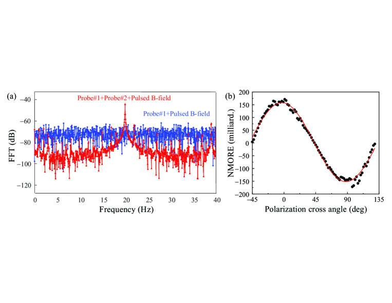
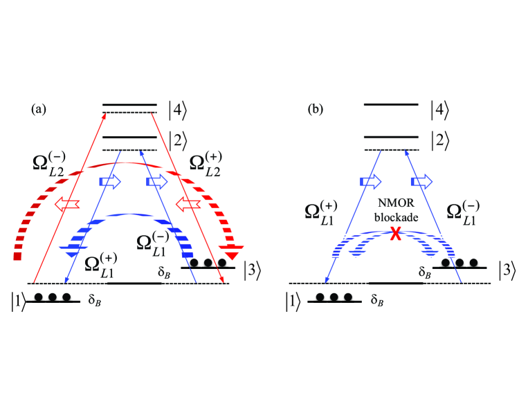
The experimental observations shown in Figs. 1(a) and 1(b) can be qualitatively explained by an inelastic-wave-scattering theoretical framework based colliding-probe bi-AM theory r16 ; r17 . Here, we consider a four-state atomic system, depicted in Fig. 2(a), where the atomic state has energy () and the lower three states form an system. We assume that the probe field (frequency ) is polarized along the -axis and propagates along the -axis. Its components couple independently the and transitions with a large one-photon detuning . Initially the population is equally shared by the two ground states , therefore two opposite two-photon transitions between states and with a two-photon detuning are simultaneously established. Here, the Zeeman frequency shift in the axial magnetic field is defined with respect to the mid-point between the two equally but oppositely shifted Zeeman levels and . A second probe field (frequency ) propagates along the -axis but has its linear polarization at an angle with respect to the -axis. Its components independently couple the and transitions with a large one-photon detuning , forming again two two-photon transitions between states and with the same two-photon detuning . More precisely, there are two excitation channels (each contains two competing two-photon transitions. i.e., and ) that share the equally-populated states and , creating a mutually influencing ground-state Zeeman coherence. We stress that the underlying physics of this new colliding-probe NMORE technique is inelastic wave scattering which has absolutely no resemblance to the usual elastic four-wave mixing or electromagnetically induced transparency based processes (see discussion later). A close analogy of this inelastic wave scattering process is the light scattering in an equally populated ground state spinors system of an atomic Bose-Einstein condensate.
Under the electric-dipole approximation, the system interaction Hamiltonian is given as
| (1) |
where is the laser detuning from state . The total electric field is given by where and with being the wavevector of the field . Here, , and where the sign distinguish the propagation directions of the two probe fields. Correspondingly, and , and . is the transition matrix element of the dipole operator .
Under the rotating wave approximation the Schrodinger equations describing wave-function amplitudes are,
| (2a) | |||
| (2b) | |||
| (2c) | |||
| (2d) | |||
where for simplicity we have expressed the decay rates of the ground and excited states as and , respectively.
The third-order perturbation calculation proceeds as follows r21 . First, with large one-photon detunings we obtain adiabatic solutions for and . We then seek corrections to steady-state solutions of ground states up to the third-order of probe fields. Finally, the polarization source terms for Maxwell equations of circularly-polarized probe components are constructed and the properties of these differential equations are analyzed.
Applying the above prescribed perturbation method we obtain for the component,
| (3) |
where , , , , and . Here, and are the total light induced frequency shift and resonance broadening. In addition, the channel-specific two-photon saturation parameters are defined as . For large one-photon detunings, and are negligible, and , . This is one of the key advantages of the far-detuned colliding-probe bi-AM technique.
Under the slowly varying envelope approximation, the Maxwell equations describing the evolution of both probe fields in the moving frame (, ) are
| (4) |
where with and being the field frequency and atom number density, respectively. Neglecting linear absorption we get for
| (5) |
where . Equation (4) contains four coupled nonlinear wave equations, similar to Eq. (5), for four complex field components. We now show that the physics of giant enhancements to NMORE signal and magnetic field sensitivity by the inelastic wave-scattering process can be understood by examining these wave equations in photon number formalism.
Letting , , where , , and are real quantities, defining and , then Eq. (5) yields
| (6a) | ||||
| (6b) | ||||
where the gain function / and is the polarization cross angle between the two linearly-polarized probe fields. When , we have . The Maxwell equations for and can be similarly obtained.
Letting , , and we immediately obtain (cp: colliding-probe, sp: single-probe)
| (7a) | ||||
| (7b) | ||||
where is exactly the single-probe NMORE per unit length with power broadening neglected r20a .
III Discussion
Remarkably, all physical effects of a single-probe AM as well as the colliding-probe bi-AM can be qualitatively understood and predicted by Eqs. (6) and (7). In fact, Eqs. (7a) and (7b) separately give the colliding-probe bi-AM NMORE heterodyne signal enhancement and theoretical detection sensitivity limit.
3.1. Single-probe NMORE blockade. It is instructive at this moment to look the case where only one probe field is present. For this widely studied single-probe scheme we neglect the third terms in Eqs. (6a) and (6b) (i.e., let ). Since the probe is the only energy source both of its components must add up, at any given propagation distance , to enforce , where is the total probe field energy at . Consequently, Eqs. (6a) and (6b) become
| (8a) | |||
| (8b) | |||
We immediately notice the gain clamping effect, , in Eq. (8a). Integrating Eq. (8a) over the propagation distance, we obtain
| (9) |
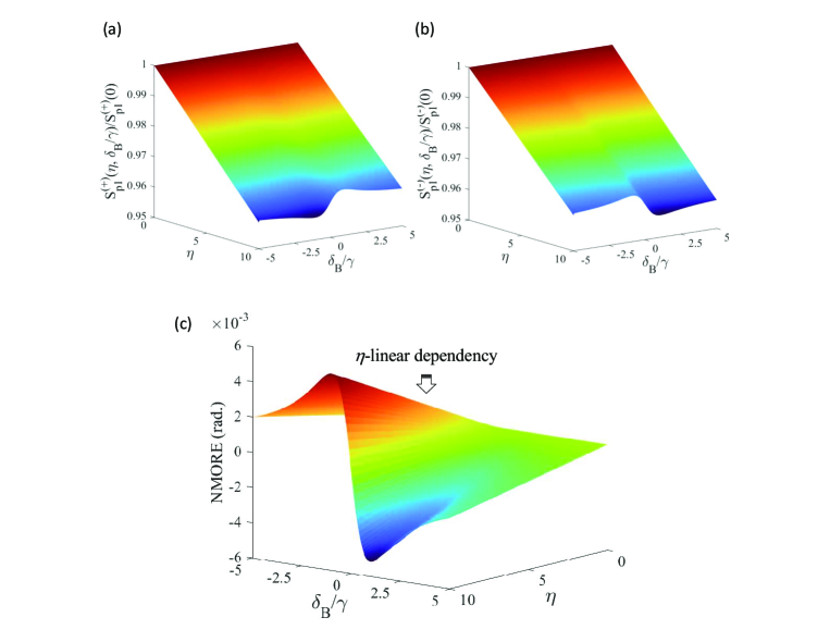
where and . Equation (9) is exactly the conclusion stated before, i.e., no appreciable change is allowed for each field component. This is a single-probe energy-symmetry-based self-limiting effect, an intrinsic symmetry-enforced NMORE blockade that blocks any directional energy flow. Figures 3(a) and 3(b) show numerical solutions of obtained from Eq.(8a). Only field intensity change is allowed by this strong NMORE blockade, as expected. We note that these results agree well with a first-principle numerical calculation without any approximation, a testimonial of the accuracy of the colliding-probe theory.
Inserting Eq. (9) into Eq. (8b) we immediately obtain the magnetic field dependent polarization angular rotation of a single-probe AM with power broadening neglected r22 , i.e.,
| (10) |
Equation (10) shows very small NMORE effect [see Fig. 3(c)]. If the one-photon detuning is reduced to improve the polarization rotation, the linear absorption will further reduce the NMORE signal amplitude attainable.
We stress that both Eqs. (9) and (10) do not exhibit any nonlinear propagation dependency which usually is a key characteristic for a process being associate to a nonlinear effect in nonlinear optics. In fact, even cross-phase modulation processes in nonlinear optics, processes that exhibit a cross-component optical power dependency similar to single-probe NMORE, do show nonlinear propagation distance dependency. Indeed, the weak linear dependency in Eq. (10) is the direct consequence of the NMORE blockade Eq. (9).
3.2. Colliding-probe bi-AM: Breaking the single-probe NMORE blockade. When the second probe field is introduced the gain function leads to enhancements to NMORE signal and magnetic field sensitivity. Intuitively, the second, counter-propagating field adds energy to the ground states shared by both probes, lifting the energy-limited growth restriction imposed by the symmetry of the first probe field to itself. More importantly, this initiates a magnetic-field-dependent directional circulating energy flow [see Fig. 2(a)], resulting in being substantially different from their initial values by propagation. We note that Eq. (6a) describes an inelastic wave scattering process where through shared and populated intermediate states a directional energy flow can occur from one probe branch into the other branch depending on branch excitation rates and magnetic field induced level shifting. Generally, the signal in the energy-accepting branch can be substantially larger than a single-probe AM operating under the same conditions. We emphasize that even though contains multiple fields and must be self-consistently evaluated with all fields, the above qualitative arguments are generally correct. Experimentally, by adjusting the ratio of two one-photon detunings we can achieve a large increase in NMORE signal interchangeably in either probe channel.
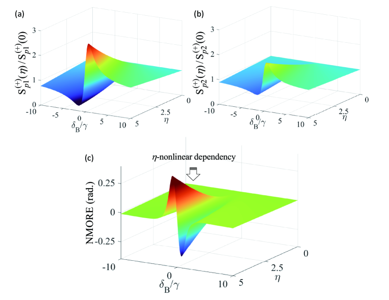
Figures 4(a) and 4(b) show nonlinear growth of field intensities and as functions of propagation distance and magnetic field. Note that field exhibits a similar “in-phase” growth as , indicating “simultaneous” stimulated emission increase in and transitions, and therefore the energy circulation as depicted in Fig. 2(a) and also qualitatively argued above.
The magnetic field dependent energy circulation can be further shown mathematically by inspecting Eq. (6a) and the Maxwell equations for that couples transition because of its counter-propagating arrangement. In order to establish an energy circulation therefore break the NMORE blockade both of these two field components must have propagation gains (i.e., increased stimulated emissions) for a given magnetic field. This is exactly what the inelastic scattering theory demonstrates. Indeed, the relevant nonlinear contributions can be expressed as
| (11a) | ||||
| , | (11b) | |||
Clearly, both components grow “in-phase” for the same , indicating the energy circulation as discussed above and the other two cross components (i.e., and ) decrease as propagation. The consequence of this directional energy flow resulting from lifting the NMORE blockade is a large polarization rotation [compare Figs. 4(c) and 3(c)]. To reach a similar signal amplitude without increasing the laser power, the one-photon detuning in a single-probe AM has to be reduced by a factor of 5, an operation condition that inevitably leads to significantly broadened magnetic resonance as well as degradation of the detection sensitivity. When the direction of the magnetic field is reversed the energy circulation is also reversed, as expected. This is exactly what has been observed experimentally.
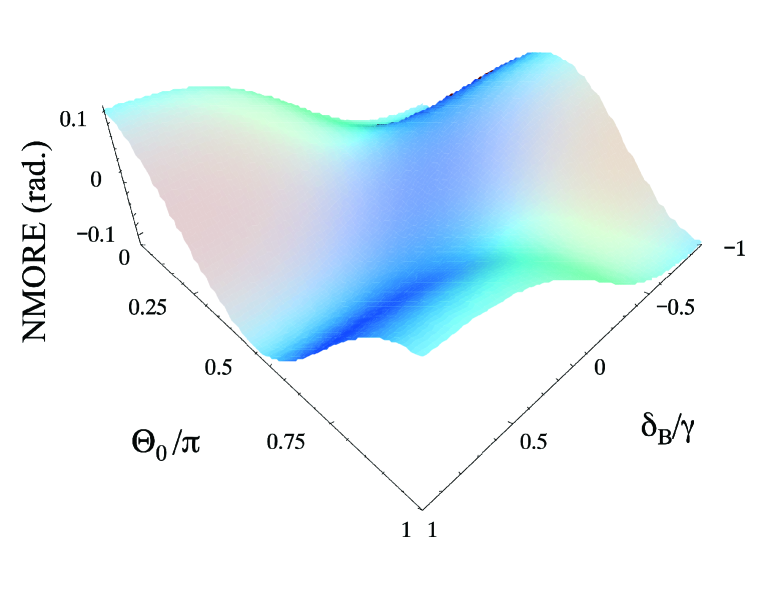
3.3. Enhancement to magnetic field detection sensitivity and NMORE cross-polarization angular dependency. The magnetic field sensitivity of the colliding-probe bi-AM can be estimated from Eq. (7b) which gives the upper limit of the sensitivity achievable using the new technique. We note that the pre-factor in Eq. (7b) is exactly the single-probe detection sensitivity per unit medium length given in Eq. (10). The dependency of exactly explains why the detection sensitivity increases as the first probe detuning increases r22 . Typically, the colliding-probe bi-AM enhanced magnetic field detection sensitivity is about 6-dB greater than the theoretical sensitivity of a single-probe AM operating under the same conditions. Experimentally, even at near resonant conditions (i.e., Doppler linewidth) where a single-probe AM has reported sensitivity r7 ; r22a , the colliding-probe technique consistently demonstrates 6-dB or better sensitivity under the same shielding and detector electronics conditions r22 . Figure 3 shows the NMORE as a function of polarization cross angle , using Eq. (7b) with included. The periodicity agrees well with the experimental observations shown in Fig. 1(b).
It is important to stress that the inelastic wave-scattering based correlated colliding-probe bi-AM is fundamental different from the usual four-wave-mixing (FWM) process as well as any electromagnetically induced transparency (EIT) based processes. Typical FWM processes, such as third harmonic generation or double- frequency conversion r21 ; r16 routinely encountered in nonlinear optics, are elastic processes where the excitation starts from a single fully populated ground state and cycles back to the same ground state. Generally, in each cycle all intermediate states have negligible populations, no appreciable energy storage or population transfer. The ground state Zeeman coherence is negligible. In addition, except the internally generated field all laser fields have no propagation effect other than linear absorption. However, the intensity of the newly generated field grows quadratically as the propagation distance. In the case of parametric FWM generation processes where more than one field are generated the growth of new fields are highly nonlinear with strict angular phase matching requirement (usually forming a radiation cone). The inelastic wave scattering based colliding-probe bi-AM process does not have any of these behaviors. Furthermore, the colliding-probe bi-AM process is not related to any electromagnetically induced transparency (EIT) based processes. In fact, the cross-component optical power dependency shown in all single-probe NMORE processes is contradictory to any EIT-based power dependency. Generally, an EIT process requires a strong coupling field to produce a large ac Stark shift, i.e, an Autler-Townes splitting. Such a strong coupling field preempts any population in the corresponding two-photon terminal state. Furthermore, for any argument attempting to interpret one probe component undergoes an EIT process there is an identically logical counter-argument against it, therefore invalidate any EIT argument.
Finally, we also note that because of large one-photon detunings (several GHz), very weak probe fields in nT magnetic field regime the inelastic wave-scattering process cannot be attributed to a pump-probe excitation process or any light-shift-based alignment-orientation effect r24 ; r25 ; r26 . More importantly, a typical pump-probe experiment, regardless of whether it employs saturated absorption spectroscopy or polarization spectroscopy, essentially relies on a two-level atomic system where the pump strongly saturates the transition while the probe is scanned across the absorption profile. In such a case only the linearized response of the probe field is considered. The SERF magnetometer, aside from its novel spin-relaxation suppression mechanism, is an example of pump-probe scheme. In fact, the probe field induced angular momentum procession/projection representation widely used in SERF magnetometers with strong on-resonance pumps r9 ; r10 ; r11 ; r12 ; r13 ; r14 is exactly the linearized probe response as in a pump-probe theory r27 . However, the colliding-probe bi-AM is based on a third-order nonlinear process. Typically, the laser powers are 20 times less than the corresponding one-photon resonance saturation power and effective excitation rates due to large one-photon detunings are two to three orders of magnitude less than the resonance saturation rate, rendering the pump-probe or alignment-orientation arguments invalid.
IV Conclusion
In conclusion, we have shown theoretically and experimentally a colliding-probe bi-AM technique that exhibits significantly large NMORE heterodyne signal enhancement as well as increased magnetic field sensitivity in comparison to widely practiced single-probe AM under the same conditions. These enhancements persist even at near resonance (although a lesser degree) where the single-probe AM has reported detection sensitivity using sophisticated and complex shielding and electronics. The inelastic wave-scattering based directional energy circulating colliding-probe theoretical framework can qualitatively explain all experimentally observed effects of this new atom magnetometry technique remarkably well. We emphasize that the far-detuned colliding-probe bi-AM technique significantly reduces probe power induced zero-field shift and broadening, complications that are unavoidable with near-resonance excitation of most single-probe AM techniques. We finally note that the multi-field-dependency of indicates correlation between the two probe fields. When the choice of detunings is in favor of one probe branch the directional energy flow drains the energy from the other probe branch. As a result the NMORE signal of the energy receiving branch increases significantly and the NMORE signal for the energy contributing branch degrades quickly. This cross-field NMORE SNR correlation is in some way similar to the “squeezing” effect for a pair of canonical variables. In a sense, the SNRs of two NMOREs from different probe branches may be viewed as a pair of “squeezing parameters” in this novel correlated colliding-probe bi-atomic magnetometer.
Acknowledgments LD thanks Dr. B. Liu (SDU) and Dr. F. Zhou (NIST) for representative data, Dr. Changfeng Fang (SDU) and Claire Deng (Thomas Wootton High School) for technical assistance on MATLAB coding and graphics. LD also acknowledges the financial support from SDU.
References
- (1) A. Weis, J. Wurster, and S. I. Kanorsky, ”Quantitative interpretation of the nonlinear Faraday effect as a Hanle effect of a light-induced bi-refringence,” J. Opt. Soc. Am. B 10, 716-724 (1993).
- (2) D. Budker, W. Gawlik, D.F. Kimball, S.M. Rochester, V.V. Yashchuk, and A. Weis, ”Resonant nonlinear magneto-optical effects in atoms,” Rev. Mod. Phys. 74, 1153 (2002).
- (3) D. Budker and D.F.J. Kimball, ”Optical Magnetometry.” Cambridge University Press (2013).
- (4) A. K. Zvezdin and V.A. Kotov, ”Modern Magneto-optics and Magneto-optical Materials,” Taylor & Francis Group, New York (1997).
- (5) W. Gawlik and S. Pustelny, ”Nonlinear Magneto-Optical Rotation Magnetometers, High Sensitivity Magnetometers,” A. Grosz, M. J. Haji-sheikh, and S. C. Mukhopadhyay, Editors, Springer Series: Smart Sensors, Measurement and Instrumentation 19, 425-450, Springer International Publishing Switzerland 2017.
- (6) M. O. Scully and M. Fleischhauer, ”High-sensitivity magnetometer based on index-enhanced media,” Phys. Rev. Lett. 69, 1360-1363 (1992).
- (7) D. Budker, V. Yashchuk, and M. Zolotorev, ”Nonlinear magneto-optical effects with ultranarrow widths,” Phys. Rev. Lett. 81, 5788-5791 (1998)
- (8) E. B. Aleksandrov et al., ”Laser pumping in the scheme of an Mx-magnetometer,” Optics Spectrosc. 78, 292-298 (1995).
- (9) W. Happer and A.C. Tam, ”Effect of rapid spin exchange on the magnetic-resonance spectrum of alkali vapors,” Phys. Rev. A 16, 1877-1891 (1977).
- (10) C.J. Erickson, D. Levron, W. Happer, S. Kadlecek, B. Chann, L.W. Anderson, T.G. Walker, ”Spin relaxation resonances due to the spin-axis interaction in dense rubidium and cesium vapors,” Phys. Rev. Lett. 85, 4237-4240 (2000).
- (11) S. Kadlecek, L.W. Anderson, T.G. Walker, ”Field dependence of spin relaxation in a dense Rb vapor,” Phys. Rev. Lett. 80, 5512-5515 (1998).
- (12) J.C. Allred, R.N. Lyman, T.W. Kornack, and M.V. Romalis, ”High-Sensitivity Atomic Magnetometer Unaffected by Spin-Exchange Relaxation,” Phys. Rev. Lett. 89, 130801 1-4 (2002).
- (13) M. V. Balabas, T. Karaulanov, M.P. Ledbetter, and D. Budker, ”Polarized Alkali-Metal Vapor with Minute-Long Transverse Spin-Relaxation Time,” Phys. Rev. Lett. 105, 070801 1-4 (2010).
- (14) A. Korver, R. Wyllie, B. Lancor, and T. G. Walker, ”Suppression of Spin-Exchange Relaxation Using Pulsed Parametric Resonance,” Phys. Rev. Lett. 111, 043002 (2013).
- (15) Y. R. Shen, ”The Principles of Nonlinear Optics,” John Wiley & Sons, Chapters 9 and 10, New York 1984.
- (16) L. Deng, M. G. Payne, W. R. Garrett, ”Inelastic four-wave mixing and multiple simultaneous interference based suppressions,” Opt. Commun. 242, 641-647 (2004).
- (17) L. Deng, M. G. Payne, and W. R. Garrett, ”Effect of multi-photon interference from internally generated fields in strongly resonant systems,” Phys. Reports 429, 123-241 (2006).
- (18) F. Zhou, C. J. Zhu, E. W. Hagley, and L. Deng, ”Symmetry-breaking inelastic wave-mixing atomic magnetometry,” Sci. Adv. 3, e1700422 (2017).
- (19) C. J. Zhu, F. Zhou, E. Y. Zhu, E. W. Hagley, and L. Deng, ”Breaking the Energy-Symmetry-Based Propagation Growth Blockade in Magneto-Optical Rotation,” Phys. Rev. App. 10, 064013 (2018).
- (20) Typically, both probe excitation rates are of the one-photon saturation rates for the relevant transitions.
- (21) Analytical solutions of single-probe NMORE for three and four-state systems with both light shift and resonance broadening included will be published separately.
- (22) Note that Ref.r7 uses sophisticated magnetic shielding and RF modulation technique. Our setup has a simple two-layer shield and no fast lock-in amplifier. This shows the great potential of the colliding-probe bi-AM technique.
- (23) B. Liu et. al., App. Phys. B (submitted).
- (24) D. Budker, D.F. Kimball, S.M. Rochester, and V. V. Yashchuk, Nonlinear Magneto-optical Rotation via Alignment-to-Orientation Conversion, Phys. Rev. Lett. 85, 2088 (2000).
- (25) For small one-photon detunings (such as those in Ref.[3]) both field-dependent frequency shift and power broaden- ing are significant and one must also include strong total field attenuation.
- (26) Giant NMORE enhancement reported here has been observed at magnetic field regime with both lasers detuned 3-5 GHz from relevant one-photon resonances using only 500 nW/1W power for probe and probe , respectively. The corresponding light shift are only about 10-20 Hz, and therefore cannot be attributed to alignment-to-orientation conversion.
- (27) We have verified experimentally that when the pump laser of a SERF magnetometer with well-calibrated sensitivity is turned off, no NMORE signal can be detected at all even at 10-nT level. This is exactly due to the single-probe NMORE blockade described in the text (B. Liu to be published).