Study of curling mechanism by precision kinematic measurements of curling stone’s motion
Abstract
Why do curling stones curl? That is a question physicists are often asked, yet no answer has been established. Stones rotating clockwise curl right, contrary to our naive expectations. After a century of debate between contradicting hypotheses, this paper provides the answer based on experimental evidence. A digital image analysis technique was used to perform precision kinematic measurements of a curling stone’s motion to identify the curling mechanism. We observed a significant left-right asymmetric friction due to velocity dependence on the friction constant. Combined with the discrete point-like nature of the friction between ice and stone, swinging around slow-side friction points has been concluded as the dominant origin of the curling. Many new angular momentum transfer phenomena have been found, supporting this conclusion.
Introduction
As one of the Winter Olympics events, the curling competition is attracting more and more attention. Along with the fun of the sport, there has been a lot of discussion about why the curling stone’s trajectory bends, i.e., curls, just like the question of the principle of a breaking ball in baseball or a lift of airplane. The curling’s mysterious behavior piques the public’s interest because of its opposite direction from the naively expected curling direction, considering the friction at the front edge. For almost a century, physicists have attempted but not succeeded in explaining the curling mechanism [1, 2, 3, 4, 5, 6, 7]. Not only that, but the situation is fraught with conflicting models, owing primarily to a lack of sufficient precise observation data.
Uniform friction over the bottom of curling stones cannot produce any systematic transverse momentum transfer. Therefore, possible hypotheses must include forward-backward asymmetry [5, 6, 7, 8] or left-right asymmetry [1, 9] of the friction strength. In addition, surface roughness is often highlighted to be necessary, which may cause discrete frictioning such as pivoting due to pebble structures on ice [10, 11, 12, 13, 14] and dust and scratching on ice by the stone’s rough bottom surface [15]. If we suppose the Coulomb friction law (the dynamic friction force must be opposite to the velocity direction), the left-right asymmetry of the continuum friction cannot transfer longitudinal to the transverse momentum [7]. For this reason, many hypotheses recently proposed are based on the forward-backward asymmetry requesting stronger friction at the back edge [16, 17, 18, 19, 20, 21, 22], or a creative idea of scratch-guide mechanism [23, 24, 25, 26, 27], but none of which are established.
Measurement
A precision trajectory measurement, including the rotation degree of freedom, was performed to begin a data-driven model-independent discussion. A digital image analysis technique, originally developed as an optical alignment system for a high-energy accelerator experiment [28] and as a displacement sensor for table-top gravity experiments [29, 30], was used.
The measurement was performed at Karuizawa Ice Park in Nagano. The stone’s positions were measured with a sub-millimeter resolution for each static video frame ( pixels) obtained at using a camera set on the top view position at above the ice surface. Positions of two labels A and B attached on the top surface of the stone (as Fig.1) were measured for each frame with a time step of . Then, positions of A and B and their center C were obtained after radial position and parallax correction as vertically projected positions on the ice plane. The coordinates were defined relative to the direction of the initial velocity. was locally defined as the starting timing for each shot. The resolution of the image analyzing system was for a single frame, and the systematic uncertainty including non-linearities in the calibration, was . However, the actual motion was disturbed by the messy vibration caused by the pebbles. All shots were made toward the direction, but their initial conditions were not precisely controlled because we made them manually. Instead, they were measured. The stone’s mass and moment of inertia were and around the center axis, respectively.
Results
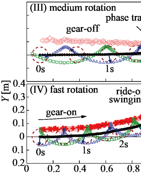
Fig.1, Fig.2, and Fig.3 show the trajectories, the time sequences of the kinematic variables for the same four typical shots, and parameter configurations. The differences between the and frames comprise translation and rotation. However, they cannot be determined uniquely. Instead, a representing point is used. For pure rotation around a center on the left side position, acts as the swinging center. On the other hand, for pure translation with no rotation.
The most symbolic phenomenon among the obtained results was the strong swinging observed before stopping, as shown in Fig.1-(IV) “ride-on swinging.” The stone swung around an almost static left position on the radius of as a simple orbital rotation. Here was set to the inner radius of the “running band” (contacting ring) of the stone’s bottom.
Similar relatively strong curling was observed, as shown in Figs.1-(II–IV) “gear-on” phase. In this phase, positions of were not static but drifted while maintaining positions, similar to engaging gears. In Figs.1-(III,IV), the velocities of (i.e., ) were almost zero, as appeared as “kinks” of the label A, B’s trajectories. In fact, Figs.2-(a,d) show during gear-on phase. As shown in Figs.1-(II,III), moved from a far distance to the position during the “gear-off” phase and then remained there stably after this “phase transition.”
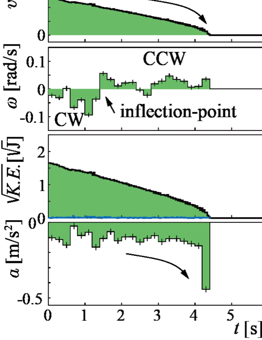
The minimum rotation shot also revealed interesting features. As shown in Fig.2-(Ia), the deceleration rate of was not constant, implyting the existence of velocity dependence of the friction constant . In fact, significantly varied as a function of time, especially at the strong-braking before the end, as shown in Fig.2-(Id). was small, but it can be highlighted that the rotation direction was significantly transitioned from CW(clockwise) to CCW (counter-clockwise) at occasionally. This transition timing coincided with the timing of the “inflection-point”, which can be noticed if we carefully observe the compressed image of the trajectory shown in the inlet figure of Fig.1-(I). It shows a transition of rightward to leftward curling. This result implies that was not simply decelerating but sometimes accelerating and that the changing of correlated with the curling. This “rotation-acceleration” phenomenon can also be found in Fig.2-(IIb) for the slow rotation shot.
The transitioning phenomena were also found for the translational motion. In Fig.2-(IIIa) “phase transition,” the deceleration rate of suddenly decreased after . It was at the point that the gear-on phase began. At the same time, started a rapid deceleration. This correlation can be well understood by checking the kinetic energies, , as shown in Fig.2-(IIIc). Their square roots were plotted to see quantities proportional to velocities. The translational and rotational components exhibited the transition, but their sum did not. This disappearance of the transition is particularly intriguing. It means that the were conserved, except for the frictional loss while transferring it between translational () and rotational () motions as
| (1) |
but the frictional loss rate was smooth without the sudden change.
The gear-off phase was also interesting, representing a situation in the actual curling games. was almost constant during the gear-off phase, as shown in Figs.2-(II,III). The transfer of translational and rotational energies helps to explain this situation. The rotational energy was fed by the translational energy, preventing deceleration due to rotational friction loss. Therefore, we should not simply interpret it as minimal rotational friction constant. In addition, the rotational energy feeds the translational energy, as shown in the deceleration relaxation of shown in Fig.2-(IIIa).
All shots we measured were analyzed, not only for the typical shots shown in Figs.1 and 2. distributions at initial and final states are plotted in Fig.4-(a). It can be confirmed that the convergence was the common feature of all shots, independent of the initial conditions , except for the minimum rotation cases. The observed peak of for the final states was compared with the running band regions of . Then, their difference should be interpreted as the azimuthal angular distribution of the actual swinging center positions, which might be spread out at approximately around .
As shown in Fig.2-(I), seems strongly dependent on . To confirm this, might be estimated using the correlation between and for the minimum rotation shots. However, of the minimum rotation shots was not precisely zero. Therefore, we should have considered the deceleration of caused by energy leakage from translation to rotation. and were used after rebinning the time sequence combining to suppress statistical fluctuations. Then, was obtained as shown in Fig.4-(b), using the local value of the gravitational acceleration of .
The remarkable velocity dependence of was confirmed, showing a rapid increase before stopping. It is crucial to understand the curling mechanism, directly implying a friction enhancement on the slower side. Fig.4-(b) also shows the fitting result, which may be useful for future model calculations attempting to predict the curling trajectories as well as microscopic studies on the physics of friction. The static friction constant measured using a spring scale was also shown, which was not used for the fitting. Interestingly, this shape is similar to the Bragg curve, which is known as the energy loss of ions passing through matters [31, 32]. The analogies with the interaction of radiation with matter, known for their application in radiation therapy, are particularly interesting.
Discussion
Let us now attempt to understand the obtained results shown above. First, the strong curling, as shown in Fig.1 “ride-on swinging,” was a clear indication of the existence of strong point-like frictions. It should be caused by pivoting due to relatively large pebbles on ice [12] or dust or scratching by the rock’s rough bottom [15] or their accidental coincidences. Therefore, these phenomena occurred by chance, with less than 50% of our rotating shots exhibiting it.
The energy/momentum transfer between translational and rotational motions was found. This was observed as the accelerating rotation in Figs.2-(Ib, IIb), as the deceleration relaxation of in the gear-on phase in Fig.2-(IIIa), and as the constant in Fig.2-(IIIb). It also meant the transfer between the orbital-angular momentum (for revolution around a fixed position) and the spin-angular momentum (for self-rotation) [33], conserving the total angular momentum as is frequently used in quantum mechanics to treat atomic systems. For and ( is the impact parameter, i.e., the perpendicular distance between the path of an incident particle and the center of force), the transfer requires offset impact, i.e., . Therefore, the observed angular momentum transfer must be caused by point-like impacts at a non-zero net offset position. Any forward-backward asymmetric friction cannot produce such angular momentum transfer because . Angular momentum transfer due to an offset collision to a fixed point cannot avoid swinging. The swinging leads to the leftward curling if the impact point is at . This can be confirmed as a coincidence of the curling inflection and the change in the minimal rotation shot as shown in Figs.1-(I), 2-(Ib). It should be interesting to compare it with the production of nuclear spin polarization via offset nuclear reactions [34, 35]. In this case, the nuclei accelerated by the particle accelerator gain spin angular momentum through offset nuclear collisions.
The converging can be understood as the frictional force at being always opposite to the direction, suppressing . The observed converging also indicates that the friction is strongest at around the direction in the running band. This backward friction at assisted rotation when via the transfer, preventing deceleration of during the gear-off phase. The stability of and during the gear-on phase must be due to the large local static friction at . It prevented from enlargement by sequentially switching the engaging points by next-to-next. The frictioning points for the gear-off phase were not static but dragged while scratching the ice, which must be caused by the relatively large at small .
The observed indicated that the probability of having discrete impacts was greater at than at because continuum friction is not a fundamental concept but only a result of an artificial coarse-graining (averaging) treatment for many real microscopic impacts. As a result, it should be concluded that the combination of 1. swinging around a discrete frictioning point on the ice (pivoting/scratching) [10, 11, 12, 13, 14, 15] and 2. the probability of the discrete frictioning is greater at the slow-side than at the fast-side because the velocity dependence of [1, 10] should be the dominant curling mechanism. The convergence meant the existence of force to generate strong local static frictioning at the slow-side, which worked as the “adhesive friction” requested in the pivoting models [10, 11, 12].
provided the left-right asymmetry of the swinging probability but was not typically the primary momentum source of the swinging. That was , which was transferred from a straight motion with the impact parameter to an orbital rotational motion with the arm length , resulting in swinging for , i.e., the slow rotating gear-off cases. can directly contribute to the swinging via transfer, but it was effective only for the fast rotation cases satisfying . It should provide an answer to the known question [10, 23] of why the total amount of curl is not proportional to, and only weakly depends on, , as shown in Fig.1, for the slow rotation cases. On the other hand, dependence was becoming visible in the faster rotation cases due to the contribution from [20]. In addition, deceleration relaxation of due to transfer during the gear-on phase should be the direct answer to why extremely fast rotating stones tend to travel further [10]. The stored intrinsic rotational energy should have been used to help the translational motion overcome friction.
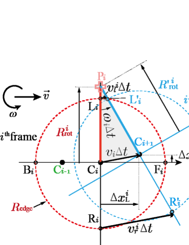
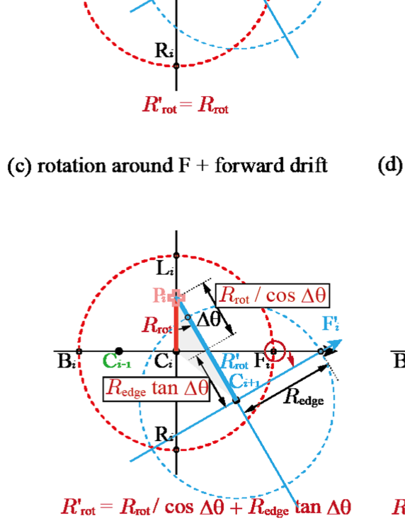
Finally, the forward-backward asymmetry was examined. Although the inhomogeneous distribution of cannot be measured directly, we can estimate it because the discrete frictioning probability is proportional to . A useful tool was comparing the lengths and . By defining
| (2) |
the swinging center positions were estimated. For example, for pure rotation around P without drifting, and for rotation around C with forward drifting. For rotation around F(B) with forward driting, . Therefore, . These are because , , and as shown in Fig.5.
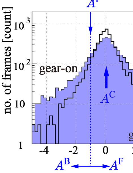
Fig.4-(c) shows the results, which were dominated by . The realistic left side swinging with forward drifting should be distributed in , which could not be resolved from in this resolution. As shown by “shoulder,” a slight asymmetry with respect to can be noticed, indicating that was preferred to for both the gear-on and -off phases. This result indicated that , which is naively acceptable but may lead to cause opposite curling. Therefore, this effect should suppress the major curling, providing another possible reason for the weak dependence of the total curl on . We found no evidence for the unnaturally large asymmetry requested by the previously proposed forward-backward asymmetry models [5, 6, 7, 8, 16, 17, 18, 19, 20, 21, 22].
In a real curling game, the brush-sweeping is effective not only for extending the stopping range by reducing but also for controlling the curling. Indeed, sweeping on the forward-right region leads to leftward curling. It is because of the reduction of the discrete frictioning on the right side. The unpredictable motion of the minimum rotation case is analogous to “knuckleball” in baseball, implying that a slight rotation should be preferred for a stable control to avoid random angular momentum transfer. The players should also remember that the occasional ride-on swinging phenomenon randomly affects the final stopping position.
Conclusion
In conclusion, it has been found that swinging around the discrete left-right asymmetric frictioning points is the dominant curling mechanism. Each part of this conclusion is not perfectly new, repeatedly suggested as attractive hypotheses in previous works [1, 10, 13, 11, 12, 14, 15]. Except for , most of the featured rich results supporting the conclusion presented here are new, indicating the angular momentum transfer and the point-like nature of friction. Future model calculations must reproduce not only curling trajectories but also the phase transition and other angular momentum transfer phenomena. This work does not propose a hypothesis but presents the principle of curling based on the model-independent experimental evidence to solve this “mystery of the century.”
Acknowledgements
Parts of this work were conducted as graduation research at Rikkyo University, by Ryota Aoki, Takaki Asada, Ran Ito, Daichi Sasagawa, and Ikumi Taira. I thank Olympic athlete Tsuyoshi Yamaguchi, staff and players at Karuizawa Ice-park for their kind assistance and discussions.
References
- [1] E. L. Harrington. Royal Society of Canada, Proceedings and Transactions, 18:247, 1924.
- [2] E. L. Harrington. Nature, 126:351, 1930.
- [3] C. W. Richardson. Nature, 125:494, 1930.
- [4] A. G. Lowndes. Nature, 127:237, 1931.
- [5] W. H. Macaulary and G. E. Smith. Nature, 125:408, 1930.
- [6] W. H. Macaulary and G. E. Smith. Nature, 127:60, 1931.
- [7] G. Walker. Nature, 140:567, 1937.
- [8] G. W. Johnston. Canadian Aeronautics and Space Journal, 27:144, 1981.
- [9] M. Denny. Canadian J. Phys., 76:295, 1998.
- [10] A. R. Penner. American J. Phys., 69:332, 2001.
- [11] M. R. A. Shegelski and E. Lozowski. Canadian J. Phys., 94:1305, 2016.
- [12] M. R. A. Shegelski and E. Lozowski. Cold Regions Science and Technology, 146:182, 2018.
- [13] K. Tusima. J. Japan. Soc. Snow Ice, 73:165, 2010 in Japanese with English abstract.
- [14] G. Mancini and L. de Schoulepnikoff. Canadian J. Phys., 97:1301, 2019.
- [15] T. Kameda et al. Sci. Rep., 10:20637, 2020.
- [16] M. R. Shegelski. Canadian J. Phys., 78:857, 2000.
- [17] M. Denny. Canadian J. Phys., 80:1005, 2002.
- [18] H. Nyberg, S. Hogmark, and S. Jacobson. Tribol. Lett., 50:379, 2013.
- [19] M. R. A. Shegelski, R. Niebergall, and M. A. Walton. Canadian J. Phys., 74:663, 1996.
- [20] E. T. Jensen and M. R. A. Shegelski. Canadian J. Phys., 82:791, 2004.
- [21] N. Maeno. Bull. Glaciol. Res., 28:1, 2010.
- [22] N. Maeno. Sports Eng., 17:33, 2014.
- [23] H. Nyberg, S. Alfredson, S. Hogmark, and S. Jacobson. Wear, 301:583, 2013.
- [24] V. Honkanen et al. Sci. Rep., 8:8123, 2018.
- [25] A. R. Penner. Tribol. Lett., 67:35, 2019.
- [26] A. R. Penner. Tribol. Lett., 68:1, 2020.
- [27] M. R. A. Shegelski and E. Lozowski. Proc. Inst. Mech. Eng., Part P: J. Sports Eng. and Tech., 233:370, 2019.
- [28] J. Murata et al. Nucl. Instrum. Meth. A, 500:309, 2003.
- [29] J. Murata and S. Tanaka. Classical and Quantum Gravity, 32:033001, 2015.
- [30] K. Ninomiya et al. Class. Quant .Grav., 34:185005, 2017.
- [31] W. H. Bragg and R. Kleeman. The London, Edinburgh, and Dublin Philosophical Magazine and Journal of Science, 8:726, 1904.
- [32] W. R. Leo. Techniques for Nuclear and Particle Physics Experiments. Springer, 2012.
- [33] Z. Farkas, G. Bartels, T. Unger, and D. E. Wolf. Phys. Rev. Lett., 90:248302, 2003.
- [34] J. Wilczyski. Phys. Lett. B, 47, 1973.
- [35] K. H. Tanaka, Y. Nojiri, T. Minamisono, K. Asahi, and N. Takahashi. Phys. Rev. C, 34:580, 1986.