Development of a Model Predictive Airpath Controller for a Diesel Engine
on a High-Fidelity Engine Model with Transient Thermal Dynamics
Abstract
This paper presents the results of a model predictive controller (MPC) development for diesel engine air-path regulation. The control objective is to track the intake manifold pressure and exhaust gas recirculation (EGR) rate targets by manipulating the EGR valve and variable geometry turbine (VGT) while satisfying state and control constraints. The MPC controller is designed and verified using a high-fidelity engine model in GT-Power. The controller exploits a low-order rate-based linear parameter-varying (LPV) model for prediction which is identified from transient response data generated by the GT-Power model. It is shown that transient engine thermal dynamics influence the airpath dynamics, specifically the intake manifold pressure response, however, MPC demonstrates robustness against inaccuracies in modeling these thermal dynamics. In particular, we show that MPC can be successfully implemented using a rate-based prediction model with two inputs (EGR and VGT positions) identified from data with steady-state wall temperature dynamics, however, closed-loop performance can be improved if a prediction model (i) is identified from data with transient thermal dynamics, and (ii) has the fuel injection rate as extra model input. Further, the MPC calibration process across the engine operating range to achieve improved performance is addressed. As the MPC calibration is shown to be sensitive to the operating conditions, a fast calibration process is proposed.
I Introduction
The paper addresses the development of diesel engine airpath control system based on Model Predictive Control (MPC). The control problem is to coordinate Exhaust Gas Recirculation (EGR) valve and Variable Geometry Turbocharger (VGT) actuators to control intake manifold pressure and EGR rate to the specified target values subject to constraints on both actuators and intake manifold pressure. Modern diesel engines rely on EGR and VGT to reduce oxides of nitrogen (NOx) emissions and turbo-lag, and they are nonlinear multivariable systems that are operated in rapid transients. Control challenges for such diesel engines have been examined for over two decades.
MPC has become of increasing interest for engine and powertrain control due to its ability to synergistically coordinate multiple actuators, satisfy constraints, and streamline the control design and calibration process, see e.g., [1, 2, 3]. For diesel engine airpath control, specifically, MPC solutions have been developed in [4, 5, 6].
With the automotive industry seeking to lessen reliance on physical prototypes, more control development is to be done based on simulation models. In this paper, a high fidelity GT-Power engine simulation model is used as an engine surrogate for controller development and verification. For this setting, we confirm the efficacy of the framework described in [7], that relies on the identified low-order Linear Parameter Varying (LPV) prediction model in the input-output form, and rate-based MPC formulation. We successfully implement and demonstrate this framework on the GT-Power engine model for a different, larger engine than in [7]. In the development of our MPC controller, we examine several choices for the prediction model and data used for identification. Specifically, we consider prediction models with two inputs (EGR valve position and VGT position) and three inputs (EGR valve position, VGT position, and fuel injection rate).
Furthermore, we examine the impact of the cylinder and intake manifold wall temperature transient dynamics on the airpath prediction model and closed-loop performance. For this, we consider identifying the LPV model from data obtained from the GT-Power [8] engine model with temperatures assumed to be in steady-state (as functions of other engine variables) and with the actual transient temperature dynamics. The former option allows to emulate several practical development scenarios, e.g., when data are collected from an engine dynamometer where thermal dynamics are dissimilar from the ones in the vehicle or when a dynamic mean-value engine model calibrated from steady-state engine data is used as an engine surrogate. Our results indicate that the controller can be successfully designed based on either choice of data, however, improved performance is obtained when the LPV model is identified from data with the transient temperature dynamics.
Finally, we find that the controller can be successfully developed without introducing nonlinear terms in the LPV prediction model; the latter approach was used in [9] to improve prediction model accuracy but at the cost of the problem becoming a nonlinear MPC problem. As a result, our framework allows MPC controller implementation based on quadratic programming and does not require an observer as model states are measured/estimated outputs (intake manifold pressure is measured and EGR rate is already estimated by the nominal strategy).
II Diesel Engine Airpath Modeling
II-A High-Fidelity Diesel Engine Model
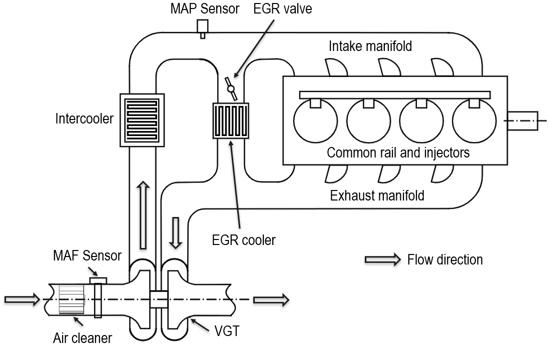
In this paper, a high-fidelity GT-Power engine model is used for the development and verification of MPC controller in simulations. The real-time capable engine model adopted in this paper represents a diesel engine with details shown in Fig. 1. The engine has four cylinders, intake and exhaust manifolds, an external EGR system and a turbocharger. There are manifold absolute pressure (MAP) and mass air flow (MAF) sensors installed to measure the intake manifold pressure and compressor flow, respectively.
The fuel injection rate is defined as the sum of the pre- and main fuel injection rates. The EGR valve controls the fluid flow rate to the intake manifold and variable geometry turbocharger (VGT) controls the intake manifold pressure by varying the amount of energy extracted from the exhaust gas, which will influence the engine output power. We assume that a set-point strategy or a supervisory controller as in [7] calculates the set-points for intake manifold pressure and EGR rate at each operating point to balance the output torque and emissions, where the EGR rate is defined as
| (1) |
where is the mass flow through the EGR valve into the intake manifold and is the throttle mass flow. The airpath controller is designed to track the target intake manifold pressure and EGR rate. Here, we assume target intake manifold pressure and EGR rate are known a priori and can be interpolated using look-up tables provided by OEM. The EGR flow and EGR rate in (1) are estimated by the nominal strategy.
II-B Control-Oriented Diesel Airpath Model
This section describes the development of the control-oriented LPV model to be used as a prediction model in MPC of the diesel engine airpath. To keep the model as simple as possible, intake manifold pressure () and EGR rate () are selected as the only states of the system () representing the airpath dynamics [9]. The model inputs are EGR valve position (percent open) and VGT position (percent close). As the intake manifold pressure is measured and EGR rate is estimated, this model structure eliminates the need for an observer. Given that the dynamics of the engine airpath are nonlinear, we develop linear models for different operating points of the engine, forming an LPV model. The engine operating points are defined by the combination of the engine speed and total fuel injection rate .
Linear models at different operating points are identified from data obtained by perturbing GT-Power model inputs () by random steps of about 10% of steady-state magnitudes. Thus, the model identified for the operating point has the following form,
| (2) |
where and are the matrices identified at the operating point with corresponding state () and input () at steady-state. To identify and in (2), Parameter Estimation toolbox in MATLAB/Simulink is used. The training data are generated from the open-loop GT-Power simulations at each while the validation data are generated from a different set of input perturbations.
To construct the LPV model, the elements of and are linearly interpolated between the 99 operating points as a function of engine speed and fuel injection rate. Since the look-up table is relatively large () and the operating points are close enough, we use linear interpolation to estimate the airpath dynamics between two adjacent operating points. The final LPV model has the following form,
| (3) |
where and .
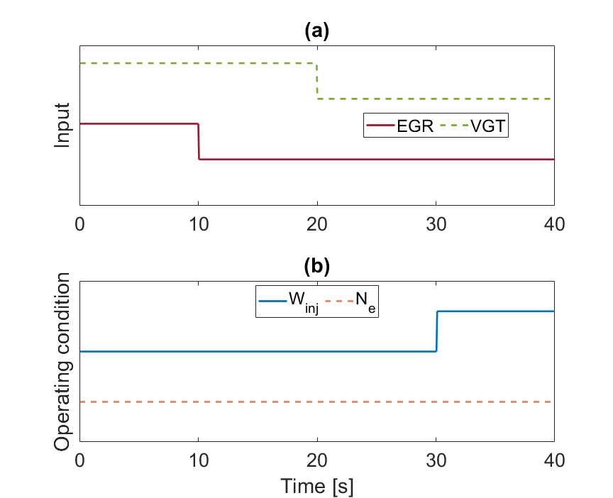
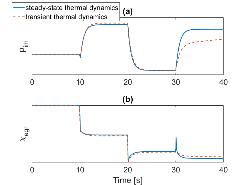
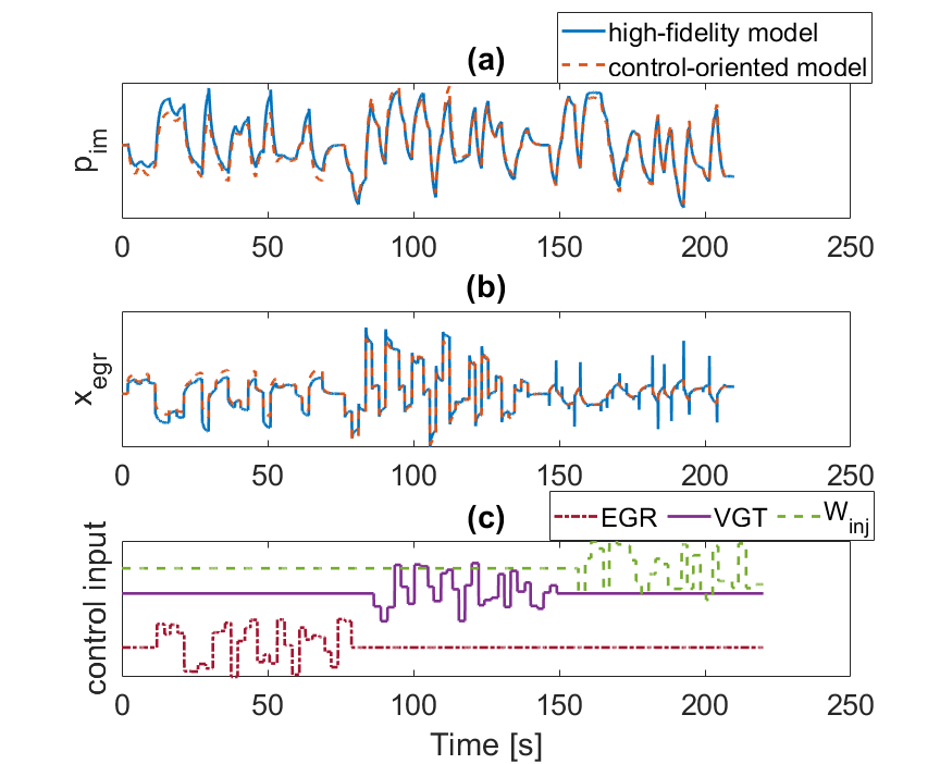
Two different sets of models (3) were identified from data generated for two cases. The first case (Case I) is based on the assumption that the thermal dynamics, such as the cylinder wall temperature and intake manifold temperature, have steady-state behavior, i.e., at a given engine speed and fuel injection rate, the temperatures remain at steady-state values. For the second case (Case II), the transient responses of the thermal dynamics are taken into account even if the engine operating condition remains the same. The and trajectories from Case I and Case II after applying the inputs shown in Fig. 2 are recorded and plotted in Fig. 3, demonstrating the effect of thermal dynamics on engine air-path responses. Fig. 3 shows that the airpath responses with transient and steady-state thermal dynamics are similar during a constant operating condition. However, when the operating condition changes, the airpath response with transient thermal dynamics, especially , will react much slower than that with steady-state thermal dynamics. To investigate how the thermal dynamics influence the LPV model accuracy, LPV models are developed based on three different strategies:
-
•
Model A: develop LPV model based on data from GT-Power model with steady-state thermal dynamics
-
•
Model B: develop LPV model based on data from GT-Power model with transient thermal dynamics
-
•
Model C: develop LPV model based on data from GT-Power model with transient thermal dynamics and fuel injection rate () as an extra input
To develop the initial LPV model (Model-A), the thermal wall solver of the GT-Power model for pipe/flowsplit walls and other thermal masses is configured to only calculate the steady-state temperature and the thermal capacitance is not considered [8]. Fig. 4 shows sample validation results of Model-A at engine speed of and fuel injection rate of . The mean model error for and are 0.0045 and 0.0024, respectively. As can be seen, at this particular operating point, Model-A is able to predict the trends in intake manifold pressure and EGR rate. Note that the numerical values are removed from the axes to preserve data confidentiality.
The second and third LPV models (Model-B and Model-C) are identified from the GT-Power model with transient thermal dynamics. Compared with Model-B, Model-C has fuel injection rate () as an extra input, which is included to better model the slow airpath responses when the fuel injection rate changes as shown in Fig. 3 from to . Inclusion of , not only changes in (3) from to , it also affects other elements of and . Thereby, and need to be re-identified. Fig. 5 shows the validation example of Model-C with three inputs at and .
II-C Validation of Control-Oriented LPV Model
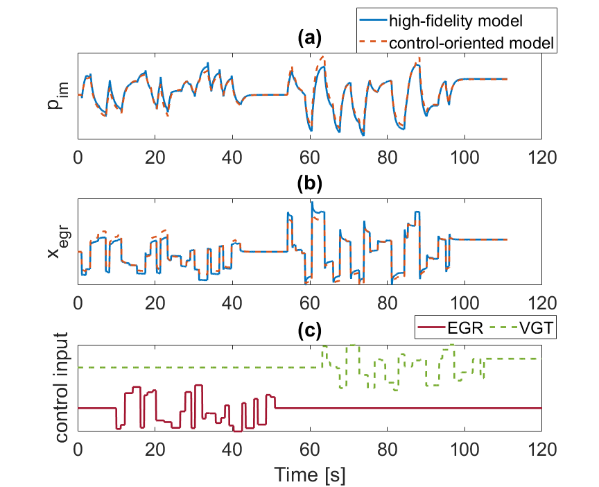
To test the performance of LPV Model-A, Model-B, and Model-C across various engine operating regions, they are simulated over the Federal Test Procedure (FTP) driving cycle. The GT-Power model with transient thermal wall solver, as the ground truth, is also simulated over the same driving cycle. The inputs to the GT-Power model are first determined according to and set-point look-up tables provided by the OEM. In the absence of a closed-loop controller, a random perturbation for both EGR and VGT signals is applied at each time step to emulate the closed-loop control signals. The same set of inputs and operating conditions are used to run all the three models in section II-B initialized with the same boundary conditions as the GT-Power model.
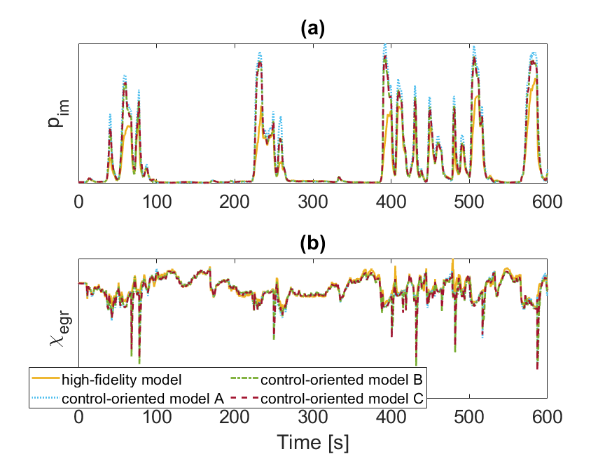
The performance of LPV models over the FTP cycle in predicting the engine airpath states are shown in Fig. 6, and compared against the high-fidelity GT-Power model. The results are also summarized in Table I.
| Model | [bar] | STD: [bar] | STD: | |
| Model-A | 0.1248 | 0.0256 | 0.2579 | 0.0448 |
| (reference) | ||||
| Model-B | 0.0873 | 0.0250 | 0.2057 | 0.0489 |
| ( 30%) | ( 2.3%) | ( 20.2%) | ( 9.2%) | |
| Model-C | 0.0884 | 0.0241 | 0.2061 | 0.0456 |
| ( 29.1%) | ( 5.8%) | ( 20.1%) | ( 1.8%) |
According to Table I, the average and prediction errors of Model-B are observed to be 30% and 2.3% less than Model-A, respectively. This shows that the model identified from data with transient thermal behavior could lead to better prediction results. Moreover, compared with Model-A, Model-C has 29.1% and 5.8% less and prediction errors, respectively. By comparing Model-B and Model-C, it can be observed that Model-C leads to slightly better prediction error by 3.5% on average. As compared to Model-A, while Model-B and Model-C lead to better prediction errors, the standard deviation of their prediction errors increase. This observation may suggest that the use of Model-B and Model-C does not necessarily lead to better predictions. For intake manifold pressure, on the other hand, the results in Table I indicate that model is sensitive to engine thermal dynamics. Such observation is consistent with the case study reported in Fig. 3. By taking into account the engine transient thermal response, either through Model-B or Model-C, the average prediction errors for from Model-B and Model-C decreases by 30% and 29.1%, respectively, as compared to Model-A.
It was demonstrated in this section that the diesel engine airpath dynamics, specifically, the intake manifold pressure, are sensitive to transient engine thermal dynamics. It was also shown that to capture such sensitivity by a control-oriented LPV model, it is beneficial to include (i) engine I/O data with transient thermal responses (Model-B), and (ii) fuel injection rate (Model-C) in the model identification process. Having a more accurate model for predicting the airpath dynamics will facilitate the design of a closed-loop controller to regulate intake manifold pressure and EGR rate. Nevertheless, one key feature of closed-loop control systems is the inherent robustness through the feedback mechanism. Given the slow dynamics of the engine thermal systems, the robustness gained through a closed-loop control policy may compensate for the impact of thermal dynamics on the airpath system, reducing the need for a more accurate LPV model. To investigate the closed-loop control system of the airpath system and its sensitivity to engine transient thermal dynamics, the developed LPV models in this section are next used to develop MPCs in the next section.
III MPC for Diesel Airpath based on LPV models
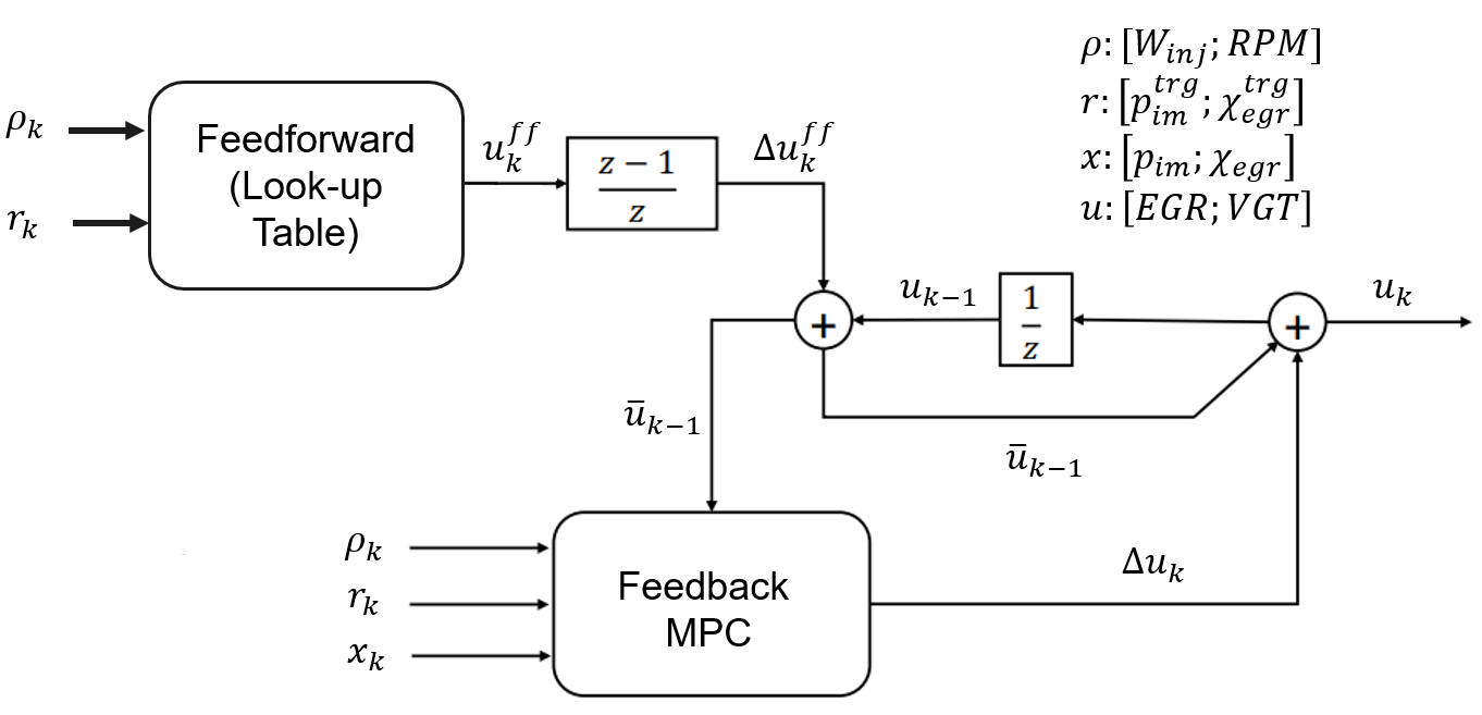
The architecture of the employed airpath control system is a combination of feedforward and feedback[7] controllers shown in Fig. 7. The feedforward controller is incorporated to speed up the airpath dynamic responses. Unlike [7], here we use a look-up table rather than an MPC loop for the feedforward (), with respect to and set-points at given engine speed and fuel injection rate values in steady-state. The feedback controller, on the other hand, is implemented for enhanced robustness and disturbance rejection.
In this paper, a linear MPC is used for the feedback loop. Due to plant-model mismatch, integral action is needed to achieve zero offset steady-state tracking. One way to incorporate integral action is using a rate-based MPC [10, 11]. With such a method, the rate-based model
| (4) |
is used, where and . The rate-based prediction model (4) is synergistic with the employed LPV framework, as the steady-state values of states and controls in (3) do not need to be known, assuming they remain constant over the prediction horizon. The feedforward control signal is interpolated from a look-up table and added to the integral action in the feedback loop, generating the final control signal applied to the system.
Based on the rate-based model (4), the MPC is formulated with the following cost function,
| (5) | |||
| subject to | |||
| (5a) | |||
| (5b) | |||
| (5c) | |||
| (5d) | |||
| (5e) | |||
| (5f) | |||
| (5g) | |||
| (5h) | |||
where is the prediction horizon and and are weighting matrices. The index runs over the prediction horizon while the index indicates the sampling instance. An augmented model is used in the MPC design with the state as extended state vector and considering as the control input. To ensure closed-loop stability, a terminal penalty on and is augmented based on the solution to the discrete algebraic Riccati equation (DARE) corresponding to dynamics and input matrices of the form,
| (6) |
with state and control weighting matrices selected by the designer,
| (7) |
A slack variable is also introduced to relax the state constraint as,
which will be weighted in the cost. Here and are limits on intake manifold pressure and EGR rate. Incorporating all these changes, the final form of the rate-based MPC is,
| (8a) | |||
| subject to | |||
| (8b) | |||
| (8c) | |||
| (8d) | |||
| (8e) | |||
| (8f) | |||
| (8g) | |||
| (8h) | |||
| (8i) | |||
| (8j) | |||
| (8k) | |||
where .
Over the prediction horizon, the operating condition is treated as fixed, which means for the model introduced in section II-B with 3-D input, throughout the prediction horizon. Thus, the third input for the MPC implementation can be ignored during optimization and the could be reduced from to by eliminating the last column of .
IV Airpath MPC Calibration
Implementation of diesel airpath MPC requires the selection of weighting matrices and in (8). Our investigation shows that it is beneficial to select and differently for different engine operating conditions. This is due to the highly nonlinear dynamics of the engine and the difference between the linear sub-models developed at different operating points. Here, we develop a framework for tuning of and pair at each engine operating point. First, for , we set the desired maximum 90 percentile response time (referred to as “response time” in the rest of the paper) and overshoot , which is modeled using a second-order system as
| (9) |
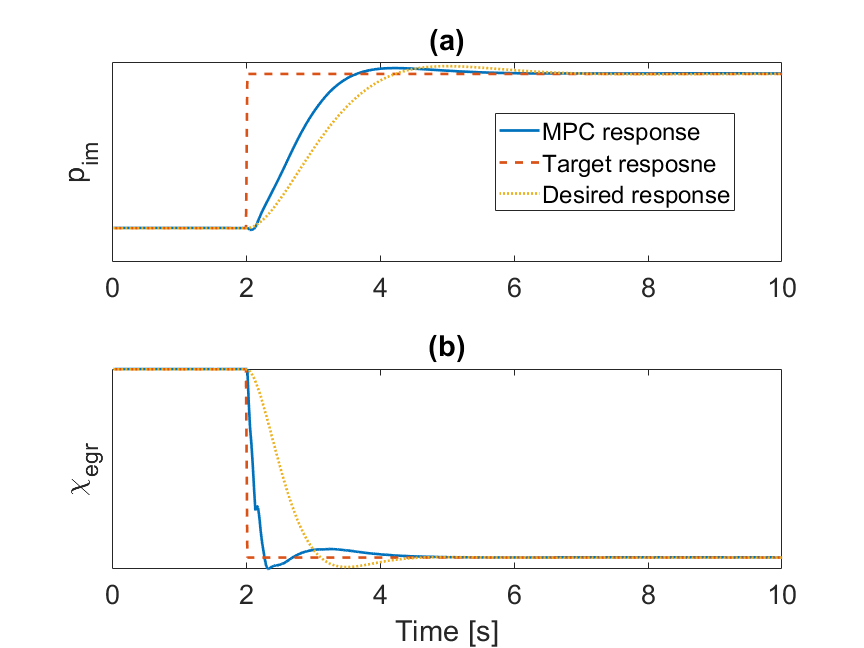
where is a discrete second order transfer function with the time constant and the overshoot . Parameters of (9) can be chosen by benchmarking another engine or requirement cascade process. Next, we apply a fuel step from the nominal fuel set-point and check if the response time of is faster than the desired value (see the yellow dot line in Fig. 8-(a)). After reaching the desired response or better, the process is repeated for tuning (see Fig.8-(b)). Finally, the results are checked to ensure both and demonstrate desirable performance. Otherwise, the process is repeated from the beginning until the desired response is reached by making further adjustments.
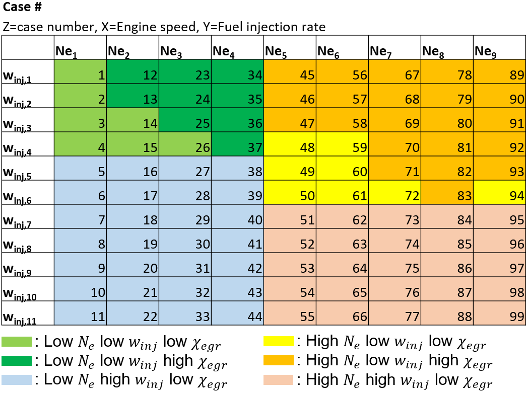
The main limitation of the tuning framework discussed above is that it needs to be repeated for each operating condition. Given there are 99 operating points, the MPC tuning process would be burdensome and time-consuming. To make the tuning process more tractable, we propose to group multiple operating points and tune the MPC for each group. The 99 engine operating points are categorized into six regions as a function of , and as shown in Fig. 9. In each region, the same and are used for MPC implementation. The six regions are defined as follows:
-
•
low , low , low ,
-
•
low , low , high ,
-
•
low , high , low ,
-
•
high , low , low ,
-
•
high , low , high ,
-
•
high , high , low .
Note that , , and are categorized using qualitative “high” and “low” terms to protect the OEM proprietary data.
V Simulation Results and Discussion
Closed-loop simulations of airpath MPC (8) are conducted over both step and transient drive cycle tests using the high-fidelity GT-Power model with transient thermal dynamics as the plant that provides feedback to the closed-loop MPC. A sampling and control update period of 20 is used, the same as the prediction model step size. The prediction horizon is , which is chosen from the average response time of and from GT-Power. The MPC is implemented using LPV Model-A, Model-B, and Model-C with soft state constraints and hard control constraints. The package MPCTools [12] is used to numerically solve the MPC optimization problem.
V-A Simple Reference Tracking Case Study
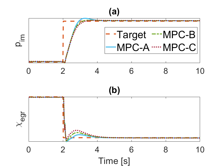
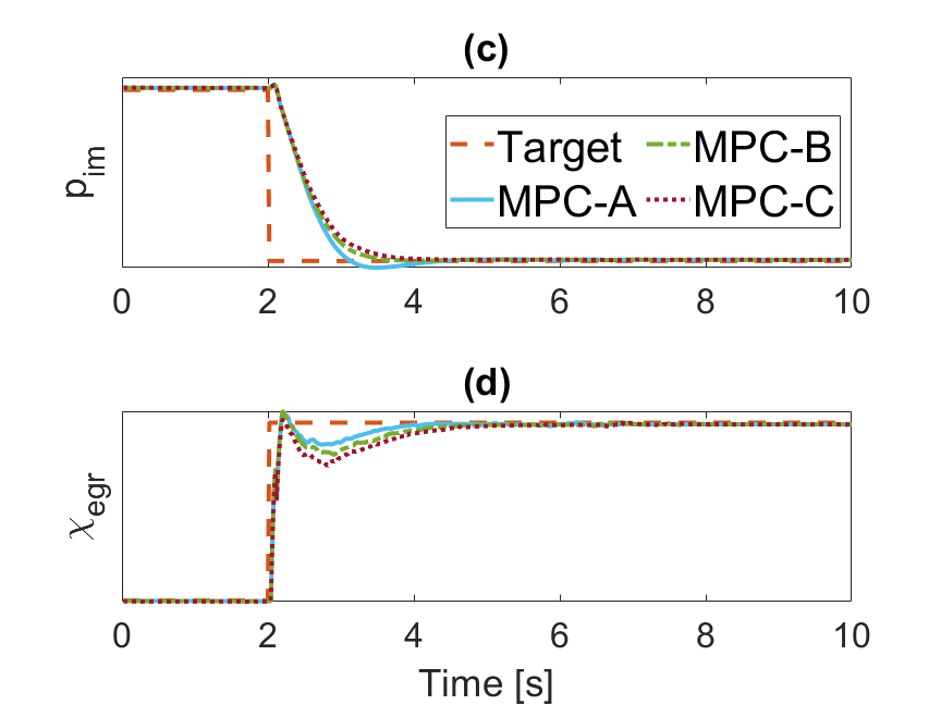
Fig. 10 shows the comparison of and response among the MPCs with LPV Model-A (MPC-A), with LPV Model-B (MPC-B), and with LPV Model-C (MPC-C) during fuel injection rate tip-in and tip-out, respectively. All of the cases have response time less than 2 and overshoot less than 5%. According to Fig. 10, all three controllers demonstrate acceptable tracking performance. The MPC-A has the largest overshoot in and the smallest overshot in while Model-C has the smallest overshoot in and largest overshot in . To further test the MPC performance, three controllers are tested based on transient drive cycle in the following sub-section.
V-B Transient Drive Cycle Implementation
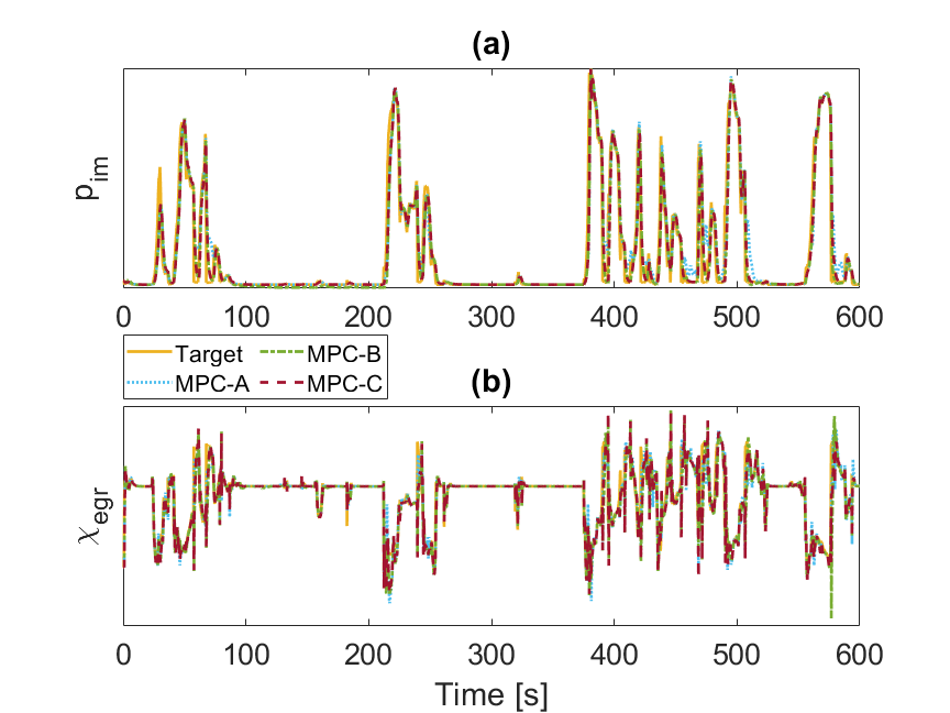
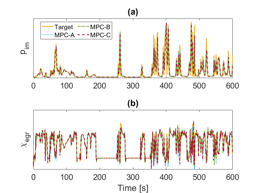
Figs. 11 and 12, and Tables II and III show the comparison of and response from the MPC-A, MPC-B, and MPC-C over the first 600 of the FTP and World Harmonized Transient Cycle (WHTC), respectively. Compared to the baseline MPC, both MPC-B and MPC-C have better tracking performance for tracking while having a similar or slightly degraded performance for tracking over FTP. Over the first 600 of WHTC, both MPC-B and MPC-C have better performance for tracking. MPC-C has the best performance for tracking. However, the tracking error with MPC-B is larger than that of MPC-A. This observation suggests that it is beneficial to consider as an additional input to the LPV model, which also fits with the conclusion from Fig. 3. Overall, all three MPCs demonstrate robustness against transient engine thermal dynamics, and are able to track the target set-points with no steady-state errors. It should be noted that all three MPCs are tuned based on the process described in section IV. Tables II and III also list the results over FTP and WHTC with only feed-forward controller for comparison, demonstrating the superior tracking performance of the combined feedforward and feedback controller as compared to the feed-forward case.
| MPC | [bar] | STD: [bar] | STD: | |
| MPC-A | 0.0789 | 0.0113 | 0.1509 | 0.0240 |
| (reference) | ||||
| MPC-B | 0.0705 | 0.0129 | 0.1368 | 0.0309 |
| ( 10.6%) | ( 14.2%) | ( 9.3%) | ( 28.8%) | |
| MPC-C | 0.0668 | 0.0113 | 0.1389 | 0.0269 |
| ( 15.3%) | ( 0%) | ( 8.0%) | ( 12.1%) | |
| FF only | 0.1399 | 0.0330 | 0.2743 | 0.0345 |
| ( 77.31%) | ( 192.0%) | ( 81.78%) | ( 43.75%) |
| MPC | [bar] | STD: [bar] | STD: | |
| MPC-A | 0.0821 | 0.0127 | 0.1528 | 0.0231 |
| (reference) | ||||
| MPC-B | 0.0801 | 0.0135 | 0.1502 | 0.0258 |
| ( 2.4%) | ( 6.3%) | ( 1.7%) | ( 11.7%) | |
| MPC-C | 0.0767 | 0.0113 | 0.1453 | 0.0215 |
| ( 6.6%) | ( 11%) | ( 4.9%) | ( 6.9%) | |
| FF only | 0.1020 | 0.0558 | 0.2121 | 0.0434 |
| ( 24.24%) | ( 339.4%) | ( 38.81%) | ( 87.88%) |
VI Summary and Conclusions
This paper described the development of a model predictive controller (MPC) for diesel engine airpath coordinated control by EGR valve and VGT actuators. A high-fidelity model of the engine in GT-Power was used as an engine surrogate for controller development and verification. By identifying the LPV prediction model from GT-Power with transient thermal solver and adding fuel injection rate to be the third input of the model, it was shown that the tracking performance of the MPC could be improved compared to when the model is identified from steady-state thermal data and has two inputs.
Acknowledgment
Dominic Liao-McPherson from ETH Zurich is gratefully acknowledged for the technical comments provided during the course of this study.
References
- [1] L. Del Re, F. Allgöwer, L. Glielmo, C. Guardiola, and I. Kolmanovsky, Automotive model predictive control: models, methods and applications. Springer, 2010, vol. 402.
- [2] P. Ortner and L. Del Re, “Predictive control of a diesel engine air path,” IEEE Transactions on Control Systems Technology, vol. 15, no. 3, pp. 449–456, 2007.
- [3] G. Stewart and F. Borrelli, “A model predictive control framework for industrial turbodiesel engine control,” in 47th IEEE Conference on Decision and Control (CDC), 2008, pp. 5704–5711.
- [4] M. Huang, H. Nakada, S. Polavarapu, R. Choroszucha, K. Butts, and I. Kolmanovsky, “Towards combining nonlinear and predictive control of diesel engines,” in 2013 American Control Conference (ACC), 2013, pp. 2846–2853.
- [5] R. Moriyasu, S. Nojiri, A. Matsunaga, T. Nakamura, and T. Jimbo, “Diesel engine air path control based on neural approximation of nonlinear MPC,” Control Engineering Practice, vol. 91, p. 104114, 2019.
- [6] M. Huang, H. Nakada, K. Butts, and I. Kolmanovsky, “Nonlinear model predictive control of a diesel engine air path: A comparison of constraint handling and computational strategies,” 5th IFAC Conference on Nonlinear Model Predictive Control (NMPC), vol. 48, no. 23, pp. 372–379, 2015.
- [7] D. Liao-McPherson, M. Huang, S. Kim, M. Shimada, K. Butts, and I. Kolmanovsky, “Model predictive emissions control of a diesel engine airpath: Design and experimental evaluation,” International Journal of Robust and Nonlinear Control, vol. 30, no. 17, pp. 7446–7477, 2020.
- [8] Gamma Technologies, GT-SUITE Help, 601 Oakmont Ln, Westmont, IL, 2020.
- [9] M. Huang, D. Liao-McPherson, S. Kim, K. Butts, and I. Kolmanovsky, “Toward real-time automotive model predictive control: A perspective from a diesel air path control development,” in 2018 Annual American Control Conference (ACC), 2018, pp. 2425–2430.
- [10] L. Wang, “A tutorial on model predictive control: Using a linear velocity-form model,” Developments in Chemical Engineering and Mineral Processing, vol. 12, no. 5-6, pp. 573–614, 2004.
- [11] G. Pannocchia, M. Gabiccini, and A. Artoni, “Offset-free MPC explained: Novelties, subtleties, and applications,” 5th IFAC Conference on Nonlinear Model Predictive Control (NMPC), vol. 48, no. 23, pp. 342–351, 2015.
- [12] M. Risbeck and J. Rawlings, “MPCTools: Nonlinear Model Predictive Control Tools for CasADi,” 2016, [online] Available: https://bitbucket.org/rawlings-group/octave-mpctools.