Resonators with tailored optical path
by cascaded-mode conversions
Optical resonators enable the generation, manipulation, and storage of electromagnetic waves [1]. They are widely used in technology and fundamental research, in telecommunications, lasers and nonlinear optics, ultra-sensitive measurements in cavity optomechanics, and the study of light-matter interactions in the context of cavity QED [2]. The physics underlying their operation is determined by the constructive interference of electromagnetic waves at specific frequencies, giving rise to the resonance spectrum [3]. This well-understood mechanism causes the limitations and trade-offs of resonator design, such as the difficulty of confining waves larger than the resonator and the fixed relationship between free spectral range, modal linewidth, and the resonator’s refractive index and size [4, 5, 6]. Here, we introduce a new class of optical resonators, generating resonances by designing the optical path through transverse mode coupling in a cascaded process created by mode-converting mirrors [7]. The generalized round-trip phase condition leads to resonator characteristics that are markedly different from Fabry-Perot resonators and can be tailored over a wide range, such as the largest resonant wavelength, the free spectral range, the linewidth, and the quality factor [4]. We confirm the existence of these modes experimentally in an integrated waveguide cavity with mode converters coupling two transverse modes into one supermode. The resonance signature of the cascaded-mode resonator is a spectrum resulting from the coherent superposition of the coupled transverse modes. We also demonstrate a transverse mode-independent transmission through the resonator and show that its engineered spectral properties agree with theoretical predictions. Cascaded-mode resonators introduce novel properties not found in traditional resonators and provide a mechanism to overcome the existing trade-offs in the design of resonators in various application areas.
Optical resonators are a cornerstone of modern physics and technology [1, 2, 3]. These optical devices have two essential functions: they provide spectral selectivity to incident light and enhance its intensity in a small volume of space [8]. A prime example of a device that exploits both spectral selectivity and field amplification within a resonator is the laser, in essence, an optical cavity in which an active medium and a pumping mechanism are present [9]. In addition, resonators with an embedded crystalline nonlinearity enable efficient frequency doubling, sum and difference frequency generation, optical parametric amplification, and optical isolation [10, 11, 12, 13, 5]. The spectral sensitivity of resonators is also widely used in chemical, biological, and thermal spectroscopy, and in optical communication networks in filters, switches, and optical delay lines [14, 4, 15]. Furthermore, the transfer of momentum between light and matter [16] can be enhanced inside a cavity, a feature widely used in cavity optomechanics. Optical resonators also provide an ideal platform to study and control quantum mechanical interactions [17, 18, 19, 20]. Finally, several collective effects arise in an array of coupled optical resonators, including an effective magnetic field for photons, non-reciprocal phase shifts, and topologically protected edge states, useful for unidirectional and robust guiding of light [21, 22, 23, 24, 25].
Motivated by this multitude of applications, various innovations have been devised to design the properties of resonators by modifying the geometry, the medium, or the reflectors of the resonators [26, 27, 28]. Most recently, various novel cavity implementations have been realized where nanostructured mirrors are engineered to manipulate the cavity’s phase shift or stability, or generally, to enable tunability of the transmitted field [29, 30, 31, 32].
Theory of cascaded-mode resonances
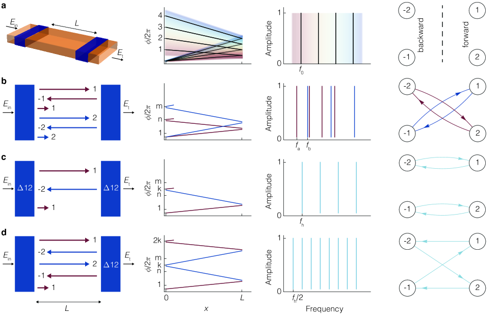
The functionality of electromagnetic resonators can be understood from the constructive interference of waves—creating resonant modes. A crucial parameter that determines these modes is the round-trip phase , accumulated by the field after completing one round trip in the resonator [2]. Waves that pick up a round-trip phase equal to a multiple of constructively interfere with themselves and become resonant modes of the resonator (Fig. 1a). In the case of a Fabry-Perot geometry, the resonance condition is then given by
| (1) |
where is the frequency of light, is an integer number representing the index of the resonant modes of frequency , is the speed of light in vacuum, is the length of the resonator, is the refractive index of the material inside the resonator, and is the reflection phase at the mirrors. This simple equation explains two essential properties of resonators: the existence of the fundamental mode and the appearance of a spectrum with only a discrete number of modes. The resulting frequency spectrum from Eq. (1) is then given by .
Above, we ignore the properties of the mode in the transversal plane. Typically, a discrete number of orthogonal transverse modes exist for each frequency, e.g., and waves, where each transverse mode experiences a different effective index (. As a result, the resonant modes of a resonator generally consist of a superposition of spectra, corresponding to the various families of transverse modes (Fig. 1b). The spectra are given by
| (2) |
We now introduce a new type of resonator based on cascaded-mode coupling. We illustrate this principle in Fig. 1c,d: upon reflection on the rightmost mode-converting mirror, an incident wave with a particular transverse mode profile is converted into another transverse mode. When this mode returns to the leftmost mirror, another mode conversion occurs upon reflection. This cascade of mode conversions can be repeated as many times as the number of transverse modes supported by the waveguide. Finally, a “supermode” emerges when the wave is converted back to the original configuration of the incident mode. For resonators with different transverse modes, the round-trip phase is given by (Supplementary Materials):
| (3) |
Here, equals with the vacuum wavelength, is the sum of all reflection phases, and is the parameter that encodes whether the contributing transverse modes appear once () or twice () in the chain. The round-trip phase is thus no longer merely determined by the length of the resonator and the refractive index but also by the number of coupled transverse modes. The corresponding resonance condition is
| (4) |
The free spectral range is thus set by the sum of the round-trip optical paths of the different cascaded modes rather than by as in a conventional resonator. Next, whereas traditional resonators feature an incoherent superposition of different spectra, each corresponding to a different transverse mode, cascaded-mode resonators exhibit just one superspectrum (Fig. 1c,d).
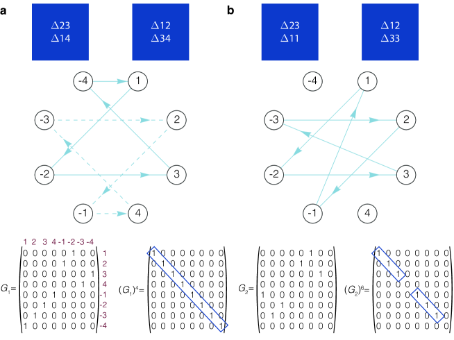
This analysis is independent of how the mode conversions are realized. For instance, in the context of transverse modes in waveguides, a mode converter can be implemented using a specific refractive index variation (blue regions in Fig. 1a-d). The last column of Fig. 1 presents a useful abstraction to visualize and study cascaded-mode resonances using directed graphs. In this picture, cascade-mode resonances appear as cyclic graphs, which allows for studying the resonators using the properties of their associated adjacency matrix. (Supplementary Materials).
Above, we only consider the round-trip phase resonance condition to get insights into the spectrum of cascaded-mode resonators. To obtain a more accurate picture of this spectrum, we need to account for both the phase and the amplitude of the different waves. The transmission spectrum of a cascaded-mode resonator, where different forward-propagating modes are coupled with each other, is given by (Supplemental Material):
| (5) |
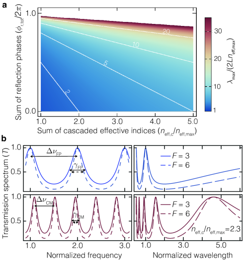
Here, , , , and are respectively the round-trip reflection coefficient, the pass-through transmission amplitude, the transmission phase, and the unit vector of the forward propagating mode (Supplemental Materials). The first striking feature of the spectrum is the modified fundamental mode wavelength. The largest wavelength that can be confined in a traditional resonator is approximately that for which . In the case of cascaded-mode resonances the largest wavelength is given by:
| (6) |
This wavelength can be much larger than the resonator?s dimensions if a significant number of transverse modes are coupled. Indeed, compared with a traditional resonance, a supermode acquires a larger propagation phase in combination with a larger reflection phase. Both effects contribute to a larger round-trip phase. In Fig. 2a we visualize the ratio of the largest wavelength in a cascaded-mode resonator to that in a traditional resonator as a function of the two preceding parameters. In the Supplementary Materials, we compare this mechanism with the mechanism underlying other subwavelength resonator designs [33, 34, 5, 29]. Here, it is important to note that the local refractive index remains unchanged in a cascaded-mode resonator. The confinement occurs through the cascading of transverse modes, which increases the round-trip phase, i.e., is being replaced by .
A second interesting feature of cascaded-mode resonances, in agreement with the geometrical model described above, is the modification of the free spectral range , given by
| (7) |
where is the group index of transverse mode at frequency .
Finally, two other crucial, spectral parameters can be engineered in a cascaded-mode resonator by controlling the round-trip phase: the linewidth and the quality factor (Fig. 2b). Unlike the previous two parameters ( and ), the linewidth and the quality factor depend on the round-trip losses (Supplementary Materials).
Not only the spectral properties but also the temporal and spatial properties of these modes can be engineered by using cascaded-mode coupling. The intracavity power build-up and the intracavity power build-up time both scale proportionally to the number of coupled modes. While the intensity of longitudinal modes in traditional resonators exhibits a simple standing-wave profile, the intensity profile in a cascaded-mode resonator will have a more irregular profile, potentially with many different local minima and maxima.
A unique spatial property of cascaded-mode resonators is that the propagation constant of a supermode depends on the propagation direction. This phenomenon is shown in its most straightforward implementation in Fig. 1c. When a field with transverse profile of mode 1 is incident on the left side of this resonator, a cascaded mode will exist with wave vector propagating from left to right, and a wave vector propagating from right to left. Due to the distinct propagation constants in opposite directions, directional nonlinear optical effects can occur in the resonator since the phase-matching conditions may only be satisfied in one direction [35]. The directionality could also give additional control over chiral, optomechanical, or quantum mechanical interactions inside the resonator.
A final property of cascaded-mode resonances that deserves special attention is the existence of mode-independent spectra. Indeed, different transverse modes at the input may excite the same resonance, i.e., a mode-independent resonance. As an example, in the resonators of Fig. 1c-d the transmission spectrum (third column) is the same for the two incident transverse modes (1 and 2). We show in Supplementary Materials that the different modes that excite the same resonance in a cascaded-mode resonator can be extracted from the adjacency matrix of the graph that encodes the different mode conversions in the resonator. The mode-independent behavior of cascaded-mode resonators is a unique transmission characteristic, a feature verified experimentally in Fig. 4. This is in contrast to traditional resonators, where different transverse modes exhibit different transmission spectra. Based on this property, it becomes possible to manipulate modes with different spatial profiles in an identical way using only one resonator.
Experiments
We experimentally realize the proposed cascaded-mode resonators using the silicon-on-insulator (SOI) platform at telecom wavelengths (1550 nm). In our on-chip implementation, the cascaded modes have distinct transverse profiles , an in-plane polarization, and propagate along waveguides rather than in free space. The SOI platform offers design flexibility in engineering the properties of the mode converters (reflection phase and magnitude), as well as the propagation properties of all modes participating in the cascade, such as their effective indices .
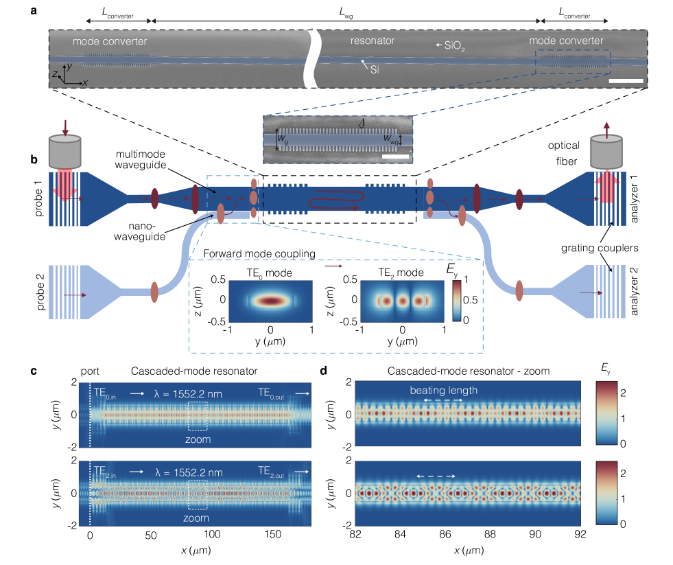
The device geometry is shown in Fig. 3a,b together with scanning electron microscope (SEM) pictures of the fabricated structures. Further details are provided in the Supplementary Materials. In general, each device consists of three main optical components: input/output waveguides that couple and guide light of chosen transverse modes to and away from the mode-converting resonators; a multi-mode waveguide section of length in which the cascaded modes are confined; specialized corrugated Bragg reflectors located on either side of the multi-mode waveguide that reflect one transverse mode into another. While, as described theoretically above, the number of conversions in a cascaded mode is only limited by the number of available transverse modes, we restrict our experimental demonstration to cascaded-mode resonators of the type shown in Fig. 1c that couple the two distinct transverse modes and . Their transverse mode profiles are shown in the inset of Fig. 3b. Consequently, the width of the waveguide in the cavity region () was chosen such that it cuts off all transverse modes of a higher order than . (See Supplementary Materials for details on the design of the individual photonic structures and their transmission/filter performance.) In addition, the grating period of the mode converters is chosen as to satisfy the phase-matching condition and provide the necessary momentum for the mode conversion to occur on the reflected wave: , with and the propagation constants of the two coupled modes. This type of coupling is typically referred to as contra-directional coupling. In the Methods, we outline in more detail the strategy for designing the cascaded-mode resonators in the SOI platform.
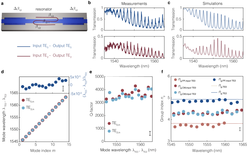
We now demonstrate in experiments and simulations the most evident signatures of cascaded-mode resonanators: the mode-independent spectrum with modified spectral parameters. The symmetric cascaded-mode resonator of Fig. 1c provides resonant confinement to input modes that correspond to either or transverse modes and has the same transmission spectrum for either input. We confirm this computationally in Fig. 3c, where we report the simulated field profile of the same cascaded-mode resonator for the two possible inputs and find a locally enhanced field inside the resonator in both cases. Moreover, the hybrid nature of the near-infrared cascaded mode inside the resonator becomes apparent in the zoom-in of the spatial profile shown in Fig. 3d. The field profile can be decomposed into a superposition of counter-propagating and waveguide modes that exhibit, as expected, the same beating length for both inputs (marked by the white arrow). We demonstrate this property experimentally by transmission spectroscopy and contrast it with two test Fabry-Perot resonators that employ standard mirrors and provide cavity confinement to only one of or modes. The experimental results are shown for the three cases in Fig. 4a-c and Supplemental Fig. S11: We find that cavity modes appear, as expected, for both and modes in the case of the cascaded-mode resonator only. Moreover, the experimental results are well-reproduced by our simulations. Cavity modes appear only for one of the two modes for the conventional Fabry-Perot resonators, while light is simply transmitted for the other modes. In the Methods, we describe the spectroscopic technique used in these measurements.
Next, we analyze the resonator properties of the cavity modes associated with the cascaded-mode resonators compared to the conventional Fabry-Perot modes in Fig. 4d-f. Firstly, we show in Fig. 4d that the intra-cavity modes of the cascaded-mode resonators excited by the two inputs ( or ) coincide in frequency. We experimentally find a negligible relative deviation between the two sets of resonant wavelengths of (. Furthermore, the quality factors of the two sets are approximately equal, as shown in Fig. 4e. Finally, the group index of the cascaded modes is approximately equal to , regardless of whether they are excited by or . In contrast, the group index of the Fabry-Perot modes are equal to and (Fig. 4f). This result confirms once more the cascaded-mode character of the measured spectra, particularly because the group index is approximately the arithmetic mean of the group indices of the participating transverse modes, in agreement with Eq. (7).
Discussion
This work shows how electromagnetic resonators can be generalized to cascaded-mode resonators, where the spectrum of supermodes reflects the generalized round-trip phase condition of a cascade of different transverse modes propagating in different directions. The theory is generally valid for any cascade of orthogonal modes inside cavities of arbitrary shape and is thus not only applicable to a cascade of transverse mode profiles of an integrated waveguide [36]. Indeed, for the round trip to occur after conversions, the -th mode in the chain needs to be indistinguishable from the first, i.e., with identical frequency, temporal shape, -vector, polarization, and phase profile [37, 38, 39]. Therefore, the theory can be applied equally well for a cascade of modes with, e.g., different spin or orbital angular momenta.
The spectral, temporal, and spatial properties are no longer solely determined by the length and refractive index of the medium, but also by the number of coupled modes. This insight allows to circumvent existing trade-offs and, for example, design resonators smaller than the local wavelength. In addition, these resonators exhibit completely new properties not found in their traditional counterparts, e.g., mode-independent resonances and directionally dependent propagation properties.
We anticipate that the concept of cascaded-mode resonators will be further exploited in a broad class of technological devices and scientific experiments since the underlying principles of cascaded-mode resonances can be extended even beyond optics.
Data and Code Availability All data and codes associated with this manuscript will be uploaded on the zenodo database prior to publication.
Acknowledgements We acknowledge support from AFOSR grants FA550-19-1-0352 and FA95550-19-1-0135. This work was performed in part at the Center for Nanoscale Systems (CNS), a member of the National Nanotechnology Coordinated Infrastructure Network (NNCI), which is supported by the National Science Foundation under NSF Award no. 1541959.
Author contributions V.G. initiated the project and conceived the concept of cascaded-mode resonators. V.G. developed the theory with inputs from I.C.B.C., J.L., M.P., and F.C.; I.C.B.C, J.L, V.G., and M.P. designed the experiment; I.C.B.C. fabricated the devices, carried out the measurements, and analysed the experimental data; J.L. carried out the numerical simulations. All authors contributed to the analysis, discussion and writing of the manuscript.
Competing interests A provisional patent application has been filed on the subject of this work by the President and Fellows of Harvard College.
References
- [1] Saleh, B. E. & Teich, M. C. Fundamentals of photonics (john Wiley & sons, 2019).
- [2] Yariv, A. & Yeh, P. Photonics: optical electronics in modern communications (Oxford university press, 2007).
- [3] Goodman, J. W. Introduction to Fourier optics (Englewood, CO: Roberts & Co. Publishers, 2005).
- [4] Bogaerts, W. et al. Silicon microring resonators. Laser & Photonics Reviews 6, 47–73 (2012).
- [5] Koshelev, K. et al. Subwavelength dielectric resonators for nonlinear nanophotonics. Science 367, 288–292 (2020).
- [6] Odit, M. et al. Observation of supercavity modes in subwavelength dielectric resonators. Advanced Materials 33, 2003804 (2021).
- [7] Ginis, V. et al. Remote structuring of near-field landscapes. Science 369, 436–440 (2020).
- [8] Armani, D., Kippenberg, T., Spillane, S. & Vahala, K. Ultra-high-q toroid microcavity on a chip. Nature 421, 925–928 (2003).
- [9] Maiman, T. Optical and microwave-optical experiments in ruby. Physical Review Letters 4, 564 (1960).
- [10] Ilchenko, V. S., Savchenkov, A. A., Matsko, A. B. & Maleki, L. Nonlinear optics and crystalline whispering gallery mode cavities. Physical Review Letters 92, 043903 (2004).
- [11] Turner, A. C., Foster, M. A., Gaeta, A. L. & Lipson, M. Ultra-low power parametric frequency conversion in a silicon microring resonator. Optics Express 16, 4881–4887 (2008).
- [12] Ji, X. et al. Ultra-low-loss on-chip resonators with sub-milliwatt parametric oscillation threshold. Optica 4, 619–624 (2017).
- [13] Sounas, D. L., Soric, J. & Alù, A. Broadband passive isolators based on coupled nonlinear resonances. Nature Electronics 1, 113–119 (2018).
- [14] Ilchenko, V. S. & Matsko, A. B. Optical resonators with whispering-gallery modes-part ii: applications. IEEE Journal of Selected Topics in Quantum Electronics 12, 15–32 (2006).
- [15] Gagliardi, G. & Loock, H.-P. Cavity-enhanced spectroscopy and sensing, vol. 179 (Springer, 2014).
- [16] Kippenberg, T. J. & Vahala, K. J. Cavity optomechanics: back-action at the mesoscale. Science 321, 1172–1176 (2008).
- [17] Vučković, J., Lončar, M., Mabuchi, H. & Scherer, A. Design of photonic crystal microcavities for cavity qed. Physical Review E 65, 016608 (2001).
- [18] Mabuchi, H. & Doherty, A. Cavity quantum electrodynamics: coherence in context. Science 298, 1372–1377 (2002).
- [19] Spillane, S. et al. Ultrahigh-q toroidal microresonators for cavity quantum electrodynamics. Physical Review A 71, 013817 (2005).
- [20] Kockum, A. F., Macrì, V., Garziano, L., Savasta, S. & Nori, F. Frequency conversion in ultrastrong cavity qed. Scientific reports 7, 1–13 (2017).
- [21] Hafezi, M., Demler, E. A., Lukin, M. D. & Taylor, J. M. Robust optical delay lines with topological protection. Nature Physics 7, 907–912 (2011).
- [22] Fang, K., Yu, Z. & Fan, S. Realizing effective magnetic field for photons by controlling the phase of dynamic modulation. Nature Photonics 6, 782–787 (2012).
- [23] Lu, L., Joannopoulos, J. D. & Soljačić, M. Topological photonics. Nature Photonics 8, 821 (2014).
- [24] Pal, V., Tradonsky, C., Chriki, R., Friesem, A. A. & Davidson, N. Observing dissipative topological defects with coupled lasers. Physical Review Letters 119, 013902 (2017).
- [25] Peng, S. et al. Probing the band structure of topological silicon photonic lattices in the visible spectrum. Physical Review Letters 122, 117401 (2019).
- [26] Englund, D., Fushman, I. & Vuckovic, J. General recipe for designing photonic crystal cavities. Optics Express 13, 5961–5975 (2005).
- [27] Levy, J. S., Foster, M. A., Gaeta, A. L. & Lipson, M. Harmonic generation in silicon nitride ring resonators. Optics Express 19, 11415–11421 (2011).
- [28] Liberal, I., Mahmoud, A. M. & Engheta, N. Geometry-invariant resonant cavities. Nature Communications 7, 1–7 (2016).
- [29] Shaltout, A. M., Kim, J., Boltasseva, A., Shalaev, V. M. & Kildishev, A. V. Ultrathin and multicolour optical cavities with embedded metasurfaces. Nature Communications 9, 1–7 (2018).
- [30] Fu, J., Jin, Y. & He, S. Metasurface for constructing a stable high-q plano-planar open cavity. Advanced Optical Materials 7, 1801339 (2019).
- [31] Xie, Y.-Y. et al. Metasurface-integrated vertical cavity surface-emitting lasers for programmable directional lasing emissions. Nature Nanotechnology 15, 125–130 (2020).
- [32] Xie, P., Wang, G. & Wang, Y. Sequentially rotated polarization conversion metasurface for circularly polarized fabry-perot cavity antenna. International Journal of RF and Microwave Computer-Aided Engineering e22725 (2021).
- [33] Kuznetsov, A. I., Miroshnichenko, A. E., Brongersma, M. L., Kivshar, Y. S. & Luk?yanchuk, B. Optically resonant dielectric nanostructures. Science 354, aag2472 (2016).
- [34] Hill, M. T. et al. Lasing in metallic-coated nanocavities. Nature Photonics 1, 589–594 (2007).
- [35] Boyd, R. W. Nonlinear optics (Academic press, 2020).
- [36] Bahari, B. et al. Nonreciprocal lasing in topological cavities of arbitrary geometries. Science 358, 636–640 (2017).
- [37] Limonov, M. F., Rybin, M. V., Poddubny, A. N. & Kivshar, Y. S. Fano resonances in photonics. Nature Photonics 11, 543–554 (2017).
- [38] Shiri, A., Yessenov, M., Webster, S., Schepler, K. L. & Abouraddy, A. F. Hybrid guided space-time optical modes in unpatterned films. Nature Communications 11, 1–10 (2020).
- [39] Piccardo, M. et al. Roadmap on multimode light shaping. arXiv preprint arXiv:2104.03550 (2021).
- [40] Mohanty, A. et al. Quantum interference between transverse spatial waveguide modes. Nature Communications 8, 1–7 (2017).
Methods
Design of the cascaded-mode resonators
We adopt a rectangular grating geometry that is symmetric with respect to the center of the ridge of the waveguide, has a periodicity and a duty cycle of 40 % as shown in Fig. 3a. The waveguide width in the corrugated area is larger than the waveguide width in between the reflectors . The phase-matching condition above is symmetric upon a permutation of and , and the mode conversion grating is reciprocal under reflection of incident light with a transverse mode profile into , and vice-versa. The selectivity of the mode converters also needs to be ensured: they need to reflect only the desired mode. We note that the grating periodicity that satisfies the contra-directional coupling condition is much shorter than the one that meets the co-directional coupling condition, in which case the converted mode would propagate in the same direction as the incident mode. Moreover, a reflection of the incident field into the same transverse mode ( into or into ) occurs if the grating periodicity satisfies or . To selectively satisfy only one of these phase-matching conditions and selectively convert only the desired modes, all periodicities need to be sufficiently different from each other. As a result, a design target is to engineer the effective indices of the two coupled modes to be as different as possible. This property is directly linked to the transverse dimensions of the waveguide. At the same time, we need to satisfy low propagation loss and good confinement of the mode to the waveguide core. As shown in Fig. S6A, and in the mode profile of Fig. 3, a waveguide width of provides an index difference of . In Fig. S10A-C we show the simulated mode conversion efficiency of the Bragg gratings used in the cascaded-mode resonator, in comparison with two test resonators which do not employ mode conversion but instead use standard Bragg mirrors that either reflect into or into .
Spectroscopic technique
The spectral response of each resonator is investigated under incident light that is either prepared to be in the or transverse mode. At first, the light is directed from an optical fiber placed above the chip into low-loss single-mode waveguides via grating couplers and adiabatic tapers. The single-mode waveguides filter any undesired higher-order transverse modes that may be excited by the grating couplers. Finally, an adiabatic taper ensures a low-loss transmission of the mode in the top arm (Fig. 3b, dark blue) from the single-mode waveguide to the multimode waveguide that precedes the cascaded-mode resonator. Importantly, we pattern around the resonator two distinct input/output ports (Fig. 3b, dark and light blue), which allow for the preparation of the input states entering the resonators and analyzed states exiting the resonator to be either in the or transverse mode. To this end, if the light is incident in the bottom arm (Fig. 3b, light blue), we generate the mode from before the resonator using a co-directional evanescent coupler based on a nano-waveguide located next to the multimode waveguide [40]. This coupling is visualized in the inset of Fig. 3b. The mode is coherently excited by the mode. From Fig. S6a, we find that this condition is satisfied if the nano-waveguide width equals 336 nm. The full-wave simulated field in Fig. S7 demonstrates an efficient forward coupling with 70% transmission at an interaction length of , as used in the experiment.
Numerical simulations
Lumerical FDTD Solutions (v8.21) is used to simulate and design the mode-converting gratings and the resonant cavity composed of them. In the simulations, the thickness of the device layer of the silicon is 220 nm. The substrate is silicon oxide. A layer of silicon oxide on top with a thickness of 700 nm is applied to protect the silicon devices. The refractive index of the silicon and silicon oxide are 3.46 and 1.46, respectively. The waveguide has a width of 1100 nm, allowing for the existence of guided modes of and around a wavelength of 1550 nm. The mesh size is 25 nm.
The period, depth, duty cycle of the gratings used for converting a forward mode to a backward propagating mode (and vice versa) is 316.5 nm, 500 nm, and , respectively. In this case, the mode conversion efficiency reaches a maximum near 1550 nm wavelength. The sweeping range of wavelength and the number of unit cells in the grating is 1350 nm to 1750 nm and 1 to 50, respectively. We use the Mode Source Module in the Lumerical software to solve the eigenmodes in the waveguide and select the or mode as the input light source into the mode converter gratings. The transmitted and reflected electromagnetic (EM) fields are recorded after the 3D full-wave simulations. The mode expansions of the recorded EM fields are performed to obtain the transmitted and reflected power of the and modes.
The resonant cavity is formed by two sets of above mentioned mode converter gratings with a cavity length of . The number of unit cells of the mode-converting mirror is chosen to be considering both a high mode-conversion efficiency and good bandwidth. The simulation time is set to be 72 ps which is long enough to get an accurate result.
Graph representation of mode-independent resonances
There are generally two ways in which mode-independent resonances can appear in a cascaded-mode resonator. These two alternatives can be most easily understood by looking at the graph representation of the resonator, as shown in Extended Data Fig. 1. As described earlier, we can recognize the resonances as the loops in the directed graph. To identify the mode-independent resonances, we can write out the different loops as a sequence of the vertices.
Mode-independent resonances can then occur within one loop or between two different loops. First, within one loop, the different nodes of the sequence all contribute to the same supermode. The resonator will thus experience mode-independent resonances for each of these modes as inputs. In addition, also two different loops can give rise to the same resonance. This is the case if the sequence of one loop can be turned into the sequence of the other by inversion of the nodes and reversing the direction of the sequence. The two alternatives are shown in Extended Data Fig. 1. In Extended Data Fig. 1b, e.g., there are mode-independent resonances for input 1, input 2, and input 3: indeed, is equivalent to and . In the case of Extended Data Fig. 1a there are two loops in the graph: (solid lines) and (dashed lines). These loops are identical after inverting the nodes and reversing the sequence of one the loops. Incidentally, the two alternatives correspond to the parameter being 1, in Extended Data Fig. 1a, or 2, in Extended Data Fig. 1b.
The different modes that activate the same supermode can also be retrieved from the graph?s adjacency matrix. For example, when the adjacency matrix raised to a power has non-zero diagonal elements for some rows, then all the rows with the same diagonal element correspond to transversal modes that excite the same mode-independent resonance, as shown in Extended Data Fig. 1.