captionUnknown document class
Optical Field Characterization using Off-axis Digital Holography
Sjoerd van der Heide(1), Bram van Esch(1), Menno van den Hout(1), Thomas Bradley(1), Amado M. Velazquez-Benitez(1),(4) Nicolas K. Fontaine(2), Roland Ryf(2), Haoshuo Chen(2), Mikael Mazur(2), Jose Enrique Antonio-López(3), Juan Carlos Alvarado-Zacarias(3), Rodrigo Amezcua-Correa(3), and Chigo Okonkwo(1)
(1) High-Capacity Optical Transmission Laboratory, Eindhoven University of Technology, 5600 MB, Eindhoven
(2) Nokia Bell Labs, 600 Mountain Ave, New Providence, NJ 07974, USA
(3) CREOL, The College of Optics and Photonics, University of Central Florida, Orlando, 32816, USA
(4) Instituto de Ciencias Aplicadas y Tecnología, Universidad Nacional Autónoma de México, Circuito Exterior S/N, Ciudad Universitaria, 04510, Mexico City.
s.p.v.d.heide@tue.nl
Abstract: Angular resolved digital holography is presented as a technique for real-time characterization of the full optical field (amplitude and phase) of space-division multiplexing components and fibers, here a 6-mode photonic-lantern is characterized.
1 Overview
Recent experimental demonstrations have shown the potential of space-division multiplexing (SDM) to greatly increase fiber transmission data rates by multiplexing spatial paths [1]. Mode-division multiplexing (MDM) , a subset of SDM , uses modes of few-mode fibers (FMFs) or multi-mode fibers (MMFs) as independent spatial paths. The optical field transmitted through these fibers is much more complex than in conventional single-mode fibers (SMFs) , making its characterization challenging. Current characterization methods include analyzing equalizer taps [2] or using an optical vector network analyzer (OVNA) [3], both require demultiplexing into single-mode domain. Therefore, these methods limit characterization to the modal basis enabled by the (de)multiplexer, for example a photonic lantern (PL) [4], which is often not well matched to the modal basis of the device-under-test (DUT) . Furthermore, the measurements of the DUT are distorted by the demultiplexer. Off-axis digital holography (DH) is able to directly measure the optical field, enabling characterization without (de)multiplexer. In many recent publications where multi-mode devices are discussed [5, 6, 7, 8, 9, 10, 11, 12, 13], DH is used to characterize the device.
In this demo, we use DH to measure optical fields in a FMF to characterize a 6-mode PL . The angular polarization multiplexing DH setup introduced in [5] is improved through inserting the reference beams via mirrors, removing the need for beam splitters in the optical path. The improved setup shows excellent temporal stability and low wavelength dependence.
2 Innovation
SDM components and fibers have an inherently greater level of complexity in their optical characterization than SMFs . With increasing research levels around MDM it is becoming necessary to have real-time advanced characterization tools which are sophisticated enough to characterize the full optical field exiting from single components but additionally from full systems of concatenated SDM components and fibers. Angular resolved DH allows characterization of the full complex optical field, while giving insight into mode-dependent loss (MDL) and cross-talk (XT) at a component and system level. Here, we detailed the developments in our angular resolved DH system which allow real-time, stable measurement of FMFs and FMF devices with an high accuracy and repeatability. The innovations can be summarized as follows, decreased temporal sensitivity to external perturbations and hence increased reliability and repeatability through precise control of the reference polarization and phase fronts. This is combined with custom digital signal processing (DSP) for real-time processing and phase front compensation.
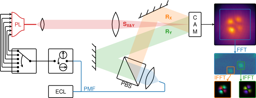
Fig. 1 shows the experimental off-axis DH setup where light exiting the facet of the PL few-mode output fiber is imaged on to a CCD camera using a 4f optical setup with lenses with focal distances of , providing 167x magnification. Off-axis DH requires a flat-phase coherent reference beam with a slight angle () with respect to the signal beam to construct a fringe pattern on the camera, after which digital analysis reveals not only the amplitude but also the phase of the signal beam. Only co-polarized signals can interfere, therefore, two reference beams with different angles and orthogonal polarizations are provided to support polarization-diverse measurements. The right-hand side of Fig. 1 shows a camera frame and a simplified explanation of the DSP chain. The camera captures the intensity of the optical field, containing the interference between signal (SX&Y) and x-, and y-polarization references (RX and RY) and can be described by
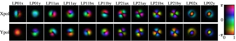
A real-valued fast Fourier transform (FFT) converts from the spatial domain to the angular domain and reveals the interference pattern for both polarizations. The signal-signal and reference-reference beating terms appear at or near DC. The two signal-reference beating terms are at an offset from DC, controlled by the angle between them. Both interference patterns are individually cropped and converted back to spatial domain using an inverse fast Fourier transform (IFFT) and now contain phase information. The measurement provides both amplitude and phase information for both polarizations, but only for a single input state of the PL . Two optical switches are used to repeat the measurement for every input port and input polarization combination of the PL , the results of which are shown in Fig. 2. Note that if results from different ports are jointly analyzed, the system is assumed stationary during the measurement, hence, any pertubations during the measurement will introduce errors in the analysis. To improve stability and strengthen the stationary assumption, the switches and camera operate very fast, switching every and completing the measurement of a 6-mode PL in .
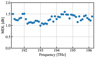
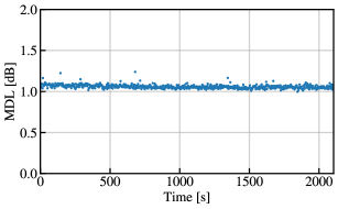
The results of the measurements, shown in Fig. 2, can be used for further processing. The measured optical signals can be digitally demultiplexed into any desired modal basis by calculating overlap integrals with that modal basis. Each overlap integral calculates one entry of a transfer matrix between the measured PL and the desired modal basis. Singular value decomposition (SVD) of this transfer matrix is used to calculate MDL . Fig. 3(a) shows the MDL as a function of optical frequency, showing good results for the C-band. Fig. 3(b) shows the MDL versus time at or , showing stable results for over half an hour.
At this point, we do not know whether the MDL variation of Fig. 3(a) is due to the wavelength dependence of the PL or the measurement apparatus, since we cannot distinguish between them. However, compared to the setup introduced in [5], beam splitters have been removed and results are more stable across the C-band. Also, the removal of beam splitters removed many reflections in the setup, making alignment easier. The setup in [5] contained two collimators, one for each reference beam, which were physically rotated to make references orthogonal. This turned out to make the setup unstable. First, any movement of the fibers to the collimators introduced a phase difference between reference polarizations, increasing MDL , requiring the fibers to be taped down rigorously even though polarization-maintaining fiber (PMF) was used. Second, any polarization rotation in the fibers leading to the reference arms was propagated to the camera, making the system unstable, again even though PMF was used. Now, a single collimator is used in conjunction with a polarization beam splitter (PBS) , decoupling any polarization rotations before the PBS from the references incident on the camera. These changes have made the setup much more stable over time.
3 OFC Relevance
DH has become an invaluable tool in our laboratory. We use it not only to characterize devices, but also to help assembly of free-space optical setups and fiber devices. For example, in [7], DH was used to assemble a multi-mode erbium-doped fiber amplifier (EDFA) . The device required fiber tapers which introduce lots of scattering and unrecoverable MDL if errors occur during fabrication. Splices, especially between different fiber types, can introduce MDL due to modal mismatch, misalignment, and fabrication errors. DH enables measuring MDL at every stage of assembly, spotting many errors which would have otherwise not been discovered until the entire EDFA was assembled. Therefore, we believe DH is a great addition to any laboratory working on fiber devices or free-space optical setups.
4 Demo content & implementation
An FMF coupling scenario will be showcased where DH helps a researcher to align two FMFs , showing MDL and transfer matrices updated in quasi real-time. The demonstration will be held remotely, with a live video link showing a computer screen and a live camera view of the laboratory. Attendees will be able to talk to the demonstrator and ask questions. Posters with schematics and photographs of the setup will be physically posted next to the computer screens at OFC. A video will be made available for on-demand attendees.
Partial funding is from the Dutch NWO Gravitation Program on Research Center for Integrated Nanophotonics (Grant Number 024.002.033), from the KPN-TU/e Smart Two program and from the Dutch NWO Visitor’s program (Grant number 040.11.743).
References
- [1] B. J. Puttnam et al., “Space-division multiplexing for optical fiber communications,” Optica 8 (2021).
- [2] M. van den Hout et al., “Experimental validation of MDL emulation and estimation techniques for SDM transmission systems,” ECOC (2020).
- [3] S. Rommel et al., “Few-mode fiber, splice and SDM component characterization by spatially-diverse optical vector network analysis,” OpticsExpress 25 (2017).
- [4] A. M. Velázquez-Benítez et al., “Scaling photonic lanterns for space-division multiplexing,” ScientificReports 8 (2018).
- [5] S. P. van der Heide et al., “Exploiting Angular Multiplexing for Polarization-diversity in Off-axis Digital Holography,” ECOC (2020).
- [6] S. P. van der Heide et al., “Low-Loss Low-MDL Core Multiplexer for 3-Core Coupled-Core Multi-Core Fiber,” OFC (2020).
- [7] J. C. Alvarado-Zacarias et al., “Assembly and Characterization of a Multimode EDFA using Digital Holography,” OFC (2020).
- [8] M. Mazur et al., “Characterization of Long Multi-Mode Fiber Links using Digital Holography,” OFC (2019).
- [9] M. Mazur et al., “Parallel Phase Stabilization of 45 Single-Mode Fiber Inputs Feeding a Mode Multiplexer,” OFC (2021).
- [10] M. Mounaix et al., “Full polarization-resolved spatiotemporal beam shaping,” CLEO-PR (2020).
- [11] M. Mounaix et al., “Time reversal of optical waves,” in Frontiers in Optics + Laser Science APS/DLS, (2019).
- [12] N. K. Fontaine et al., “Laguerre-Gaussian mode sorter,” Nat.Communications 10 (2019).
- [13] N. K. Fontaine et al., “Digital turbulence compensation of free space optical link with multimode optical amplifier,” ECOC (2019).