Generation and characterization of customized perfect Laguerre-Gaussian beams with arbitrary profiles
Abstract
We experimentally demonstrate the generation of customized perfect Laguerre-Gaussian (PLG) beams whose intensity maxima localized around any desired curves. The principle is to act appropriate algebraic functions on the angular spectra of PLG beams. We characterize the propagation properties of these beams and compare them with non-diffraction caustic beams possessing the same intensity profiles. The results manifest that the customized-PLG beams can maintain their profiles during propagation and suffer less energy loss than the non-diffraction caustic beams, and hence are able to propagate a longer distance. This new structure beam would have potential applications in areas such as optical communication, soliton routing and steering, optical tweezing and trapping, atom optics, etc.
I Introduction
Structure lights with customized intensity, phase, and polarization distributions Rubinsztein-Dunlop et al. (2016); Forbes et al. (2021) have promoted the development of fundamental physics Hansen et al. (2016), optical tweezers Baumgartl et al. (2008), imaging Vettenburg et al. (2014), optical communications Torres (2012), and light-matter interactions Wang et al. (2021); Chen et al. (2021), etc. Hermite–Gaussian (HG) beamAbramochkin and Volostnikov (2010); Wang et al. (2016), Laguerre–Gaussian (LG) beam Allen et al. (1999), and Ince–Gaussian beam Bandres and Gutiérrez-Vega (2004); Yu et al. (2021) are three representative structure lights, which are the solutions of the paraxial wave equation (PWE) under Cartesian, polar, and elliptical coordinates, respectively. These beams can remain their transverse profiles unchanged for about one Rayleigh length propagation, but their beam sizes would expand due to diffraction. In 1987, J. Durnin et al. propose that the zeroth-order Bessel beam possesses the non-diffraction characteristic Durnin et al. (1987), that is their transverse structures neither deform nor expand over a significant propagation distance. This kind of beam displays a highly localized concentric ring structure, which is similar to the LG modes Mendoza-Hernández et al. (2015). However, a Bessel beam theoretically has infinite ring numbers and each ring carries equal energy, meaning that a Bessel beam has infinite energy and is inaccessible practically. So in experiment, the Bessel beams are apodized, e.g., by a Gaussian transmittance Gutiérrez-Vega and Bandres (2005) and can propagate up to a finite distance without obvious diffraction. Recently, researchers make use of the formal connection between Bessel beams and LG beams (i.e., the relationship between the radial wave number of Bessel beam and the beam waist of LG beam) to propose a new spatial structure beam in theory, referred to as the perfect Laguerre-Gaussian (PLG) beam Mendoza-Hernández et al. (2020), and it was later verified experimentally Liu et al. (2021). The most striking difference between the PLG beam and the LG beam is that its outer ring’s radius is independent of the topological charge.
The structure beams mentioned above have specific optical field expressions and transverse intensity distributions. In some applications such as bio-particle transportation, atom trapping and manipulation, and soliton routing and steering, light beams with intensities concentrated along arbitrary desired trajectories would be more useful. However, structure beams (e.g., optical images) obtained through simple amplitude modulation by optical instruments are susceptible to diffraction and can not preserve their spatial profiles during propagation. To overcome this, researchers propose some methods to generate quasi-non-diffraction beams via spatial spectrum engineering techniques assisted with some optimization algorithms such as genetic algorithm Sanchez-Serrano et al. (2012), iterative Fourier algorithm López-Aguayo et al. (2010); Wang et al. (2022), differential evolution algorithm Martínez-Herrera et al. (2019). In 2020, A. Zannotti et al. construct arbitrary non-diffraction caustic beams through amplitude and phase modulation of the Bessel beam in Fourier space Zannotti et al. (2020). This beam can propagate a Rayleigh length while keeping its shape and size basically unchanged. Recently, J. Mendoza-Hernández theoretically proposes that by acting an algebraic function on a PLG beam in Fourier space, a new structure beam similar to the non-diffraction beam can also be generated Mendoza-Hernández (2021). It’s demonstrated that such a beam can preserve their profiles a longer propagation distance than the non-diffraction beam. Nevertheless, this work doesn’t extend to generating arbitrarily shaped beams and yearning for experimental realization.
In this paper, we experimentally generate customized-PLG beams with any desired shapes. The rationale is based on tailoring the PLG beams in Fourier space by algebraic functions Martinez-Castellanos and Gutiérrez-Vega (2015); Mendoza-Hernández et al. (2019); Mendoza-Hernández (2021), which are constructed using the methods in Ref. Zannotti et al. (2020). To assess the propagation properties of the customized-PLG beams, we also generate non-diffraction caustic (or customized-Bessel) beams Zannotti et al. (2020) with the same transverse profiles for peer comparison. The experimental results show that the customized-PLG beams can maintain their profiles during propagation and suffer less energy loss than the customized-Bessel beams, and hence can propagate a longer distance.
II Theoretical description
When a linear differential operator acts on an appropriate seed beam , a new beam can be obtained with an arbitrary desired shape Martinez-Castellanos and Gutiérrez-Vega (2015); Mendoza-Hernández (2021). Such a transformation process can be expressed as
| (1) |
where is the transverse coordinate. Using the Fourier transform and inverse Fourier transform , Eq. (1) can be further written as
| (2) |
where is an algebraic function corresponding to the operator in Fourier space Martinez-Castellanos and Gutiérrez-Vega (2015), is the Fourier transform of .
In this paper, we consider the two cases of seed beam: 0th-order Bessel beam and PLG beam. The seed-Bessel beam in Fourier space is a thin ring, which is defined as
| (3) |
where is the delta function with ring radius (its ring width is infinitesimal).
The seed-PLG beam, used to produce the PLG beam and its derived structured light field, is defined as
| (4) |
where is a constant coefficient, is the Laguerre polynomial with the radial order and azimuthal order , with the input Gaussian beam waist and .
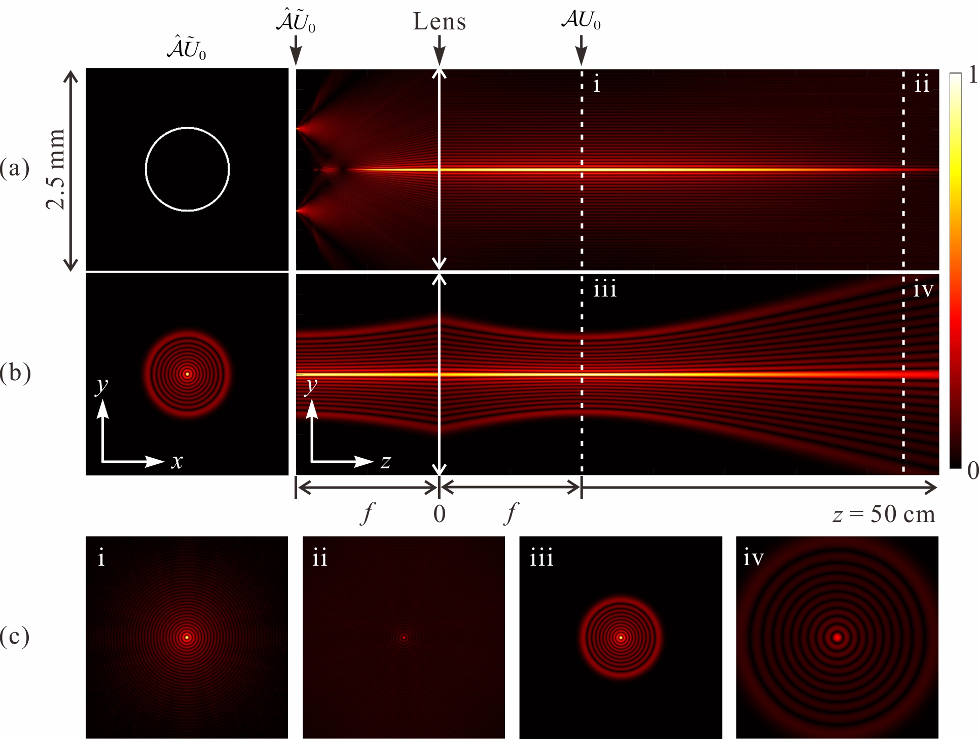
In the simplest case, namely acting on or and takes the inverse Fourier transform by a lens, a Bessel or PLG beam is generated. Figure 1 shows the theoretical simulation of this conversion process (the relevant parameters are given in the caption). The first columns of Fig. 1(a) and 1(b) are the transverse structures of and , and the second columns are the beams’ propagation trajectories. The images and in Fig. 1(c) are the Bessel and PLG beams obtained at the focal plane of the converging lens, while images and present their transverse intensity profiles at a propagation distance of 45 cm. As can be seen that the Bessel beam maintains its overall profile during propagation but its intensity attenuates fastly whereas the PLG beam can maintain its intensity profile much better but suffer a little broadening.
To produce diverse shaped beams, we can select or construct more complicated . Figure 2(a) and 2(b) give two examples of designed astroid and deltoid distributions when the algebraic functions are selected as and Zannotti et al. (2020). Here is the azimuthal angle in spatial-frequency domain, and are constants. The first columns show the angular spectra corresponding to and , the second columns and the third columns are the intensities and the phase distributions of the customized beams. As we can see, under the set parameters, for the same algebraic function, the customized fields constructed by the two seed beams have very similar spatial structure, which ensures their comparability in propagation characteristics.
To generate more universal beams that have no explicit function forms, we adopt the ‘Bessel-pencil’ method Zannotti et al. (2020) for reference to construct their algebraic functions. This method utilizes the most localized propagation-invariant light spot, namely a 0th-order Bessel beam, as a ‘pencil’ to draw the desired beam along a preset curve. The algebraic function of such a beam can be constructed by
| (5) |
where and are the amplitude and phase of , respectively, is a variable parameter in the range from 0 to 2 to determine the scale and details of the customized beam Durnin (1987), is the transverse coordinate along the desired curve, is a unit vector, and is the arc length of the curve, and is the head /tail of the curve. The phase term should grow with the curve’s arc length , which can be obtained by
| (6) |
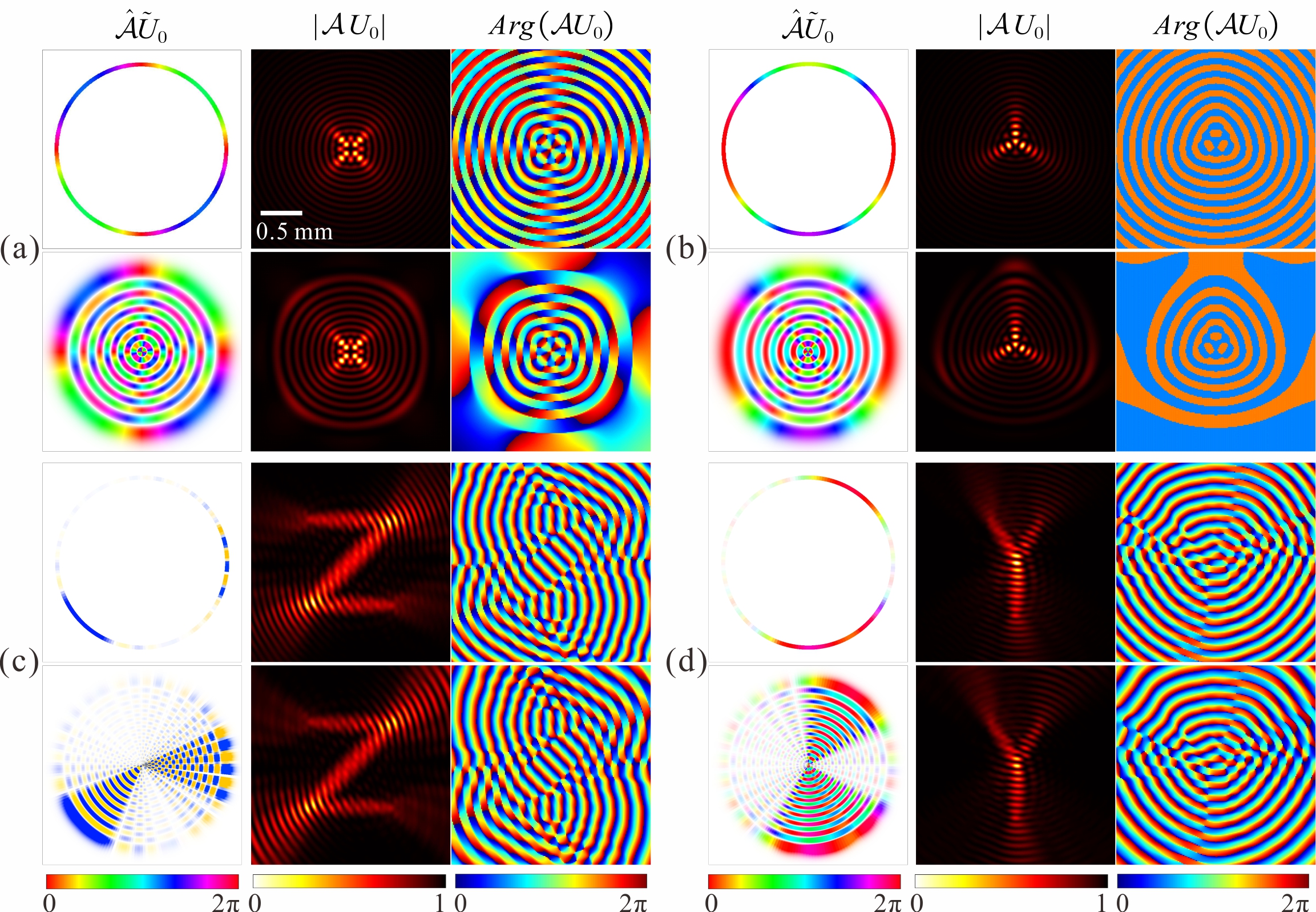
We integrate Eq. (5) along two designed curves, i.e., a letter ‘Z’ and a letter ‘Y’, and obtain the corresponding algebraic functions and . Acting them on and respectively, we obtain four angular spectra, as shown in the first columns of Fig. 2(c) and 2(d). The second columns are the intensity distributions of the corresponding target beams, from which we can see that the beams’ intensity maxima indeed follow the shapes of the letters ‘Z’ and ‘Y’.
III Experimental results and discussions
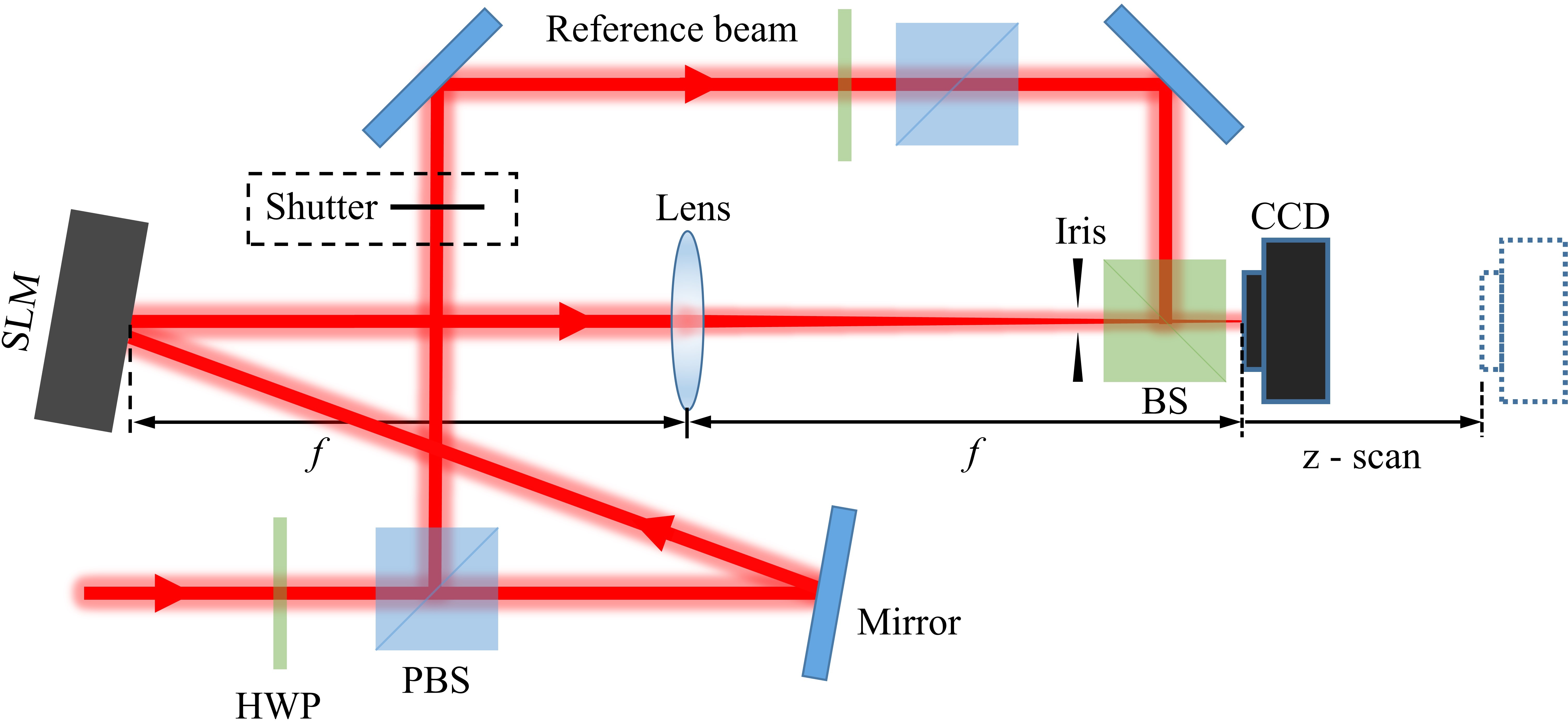
In the following we experimentally generate several representative customized-PLG and customized-Bessel beams based on the methods above. The experimental setup is illustrated in Fig. 3. A horizontally polarized Gaussian beam incident on a spatial light modulator (SLM) carried with a pre-calculated phase, and the reflected beam is modulated to the target . The desired beam can be obtained by inverse Fourier transform of using a lens. A charge-coupled device (CCD) is placed at the focus of the lens to capture the beam’s transverse profile. The position of the CCD can also be shifted through a translation stage to record the revolution of the beam during its propagation. Besides, an additional reference beam can be switched on by a shutter to interference with the customized beams for phase measurements.
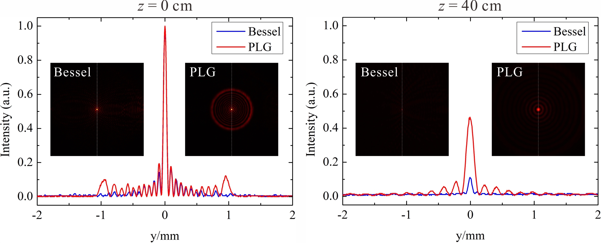
Firstly we let to generate a Bessel beam and a PLG beam (Fig. 4). The related parameters used in the experiment are mm, m, mm, =10, and mm, as in theory. The values of and ensure that the two types of beams have the same intensity distributions in the focal plane of the lens, as can be seen in Fig. 4(a). Theoretically smaller enables a more ideal Bessel beam. But practically we set m since it almost approaches the resolution of the SLM, and a smaller will decrease the modulation quality and the generation efficiency of the target beam. Figure 4(b) shows the intensity distributions of the two beams after propagating a distance of 40 cm in free space. The Bessel beam depletes severely and its intensity maximum drops to 10%, while the PLG beam depletes much slower and its intensity maximum falls to 46%. Meanwhile, the side-lobs of the PLG beam are also more recognizable than that of the Bessel beam after propagation.
Next, we generate several complicated patterns, e.g., astroid, deltoid, ‘Z’-shaped, and ‘Y’-shaped beams, and record their intensity distributions after propagation distances of 0 cm, 20 cm, and 40 cm, as shown in Fig. 5, where (a), (c), (e), and (g) corresponds to the customized-Bessel beam and (b), (d), (f), and (h) corresponds to the customized-PLG beam. The related parameters are the same with Fig. 4 except for =20 for (f) and (h). At , the central regions of both beams are tailored into the same desired shapes. The difference is that the customized-PLG beams’ outer rings are more pronounced than that of the customized-Bessel beam. This is due to that the intensities of the PLG’s outer rings are higher, as can be seen in Fig. 1 and Fig. 4. During propagation, the customized-Bessel beams exhibit non-diffraction characteristics but their intensities decay dramatically and are almost invisible after a propagation distance of more than 40 cm. In contrast, the customized-PLG beams also maintain their overall shapes except for little deformations and expansions with the increase of the propagation distance, while their intensities deplete much slower and are still recognizable over 40 cm propagation distance. As can be seen from the above results that the propagation properties of customized beams follow that of the corresponding seed beams. This is due to that the customized beams could be considered as the coherent superposition of the seed beams Zannotti et al. (2020).
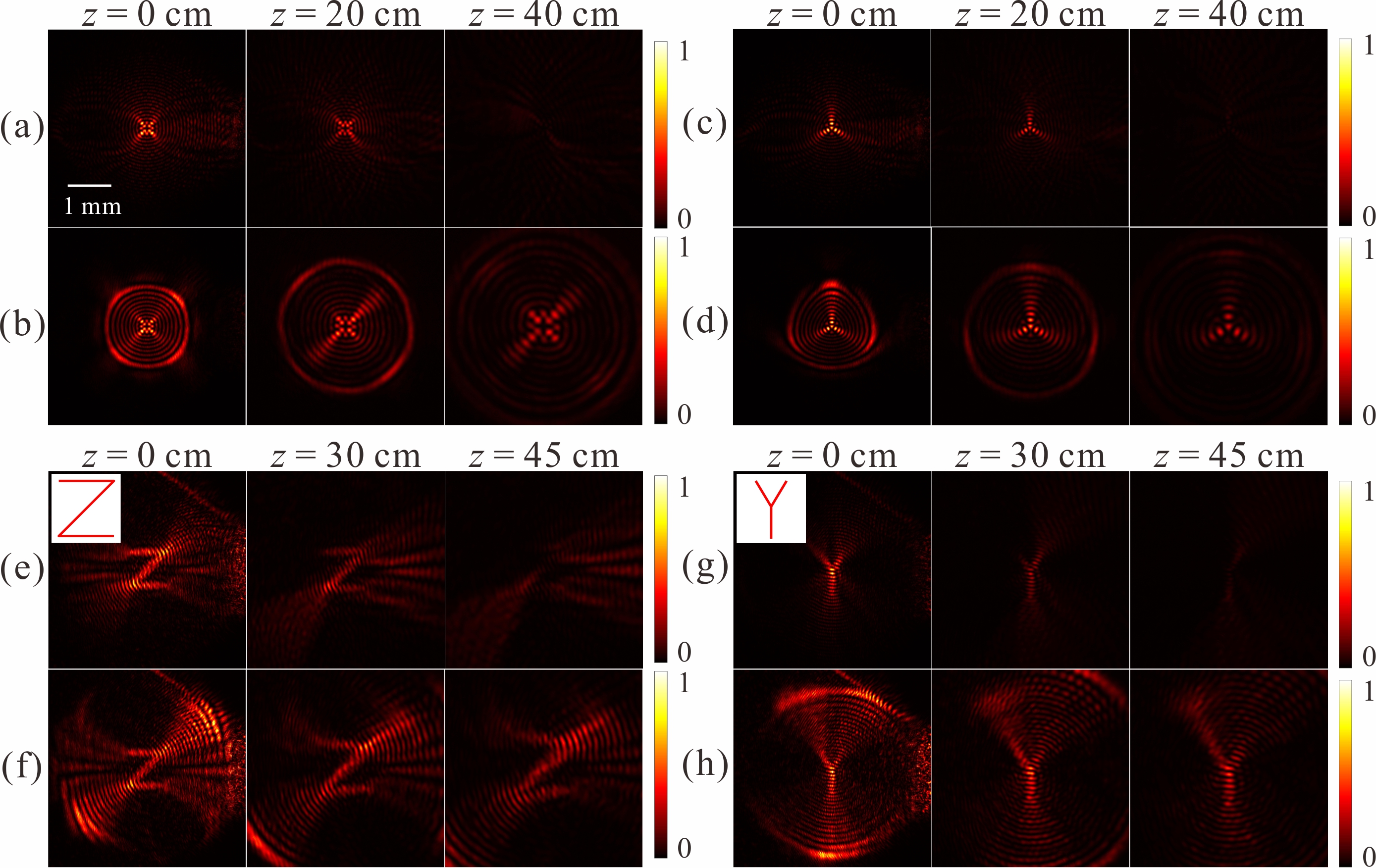
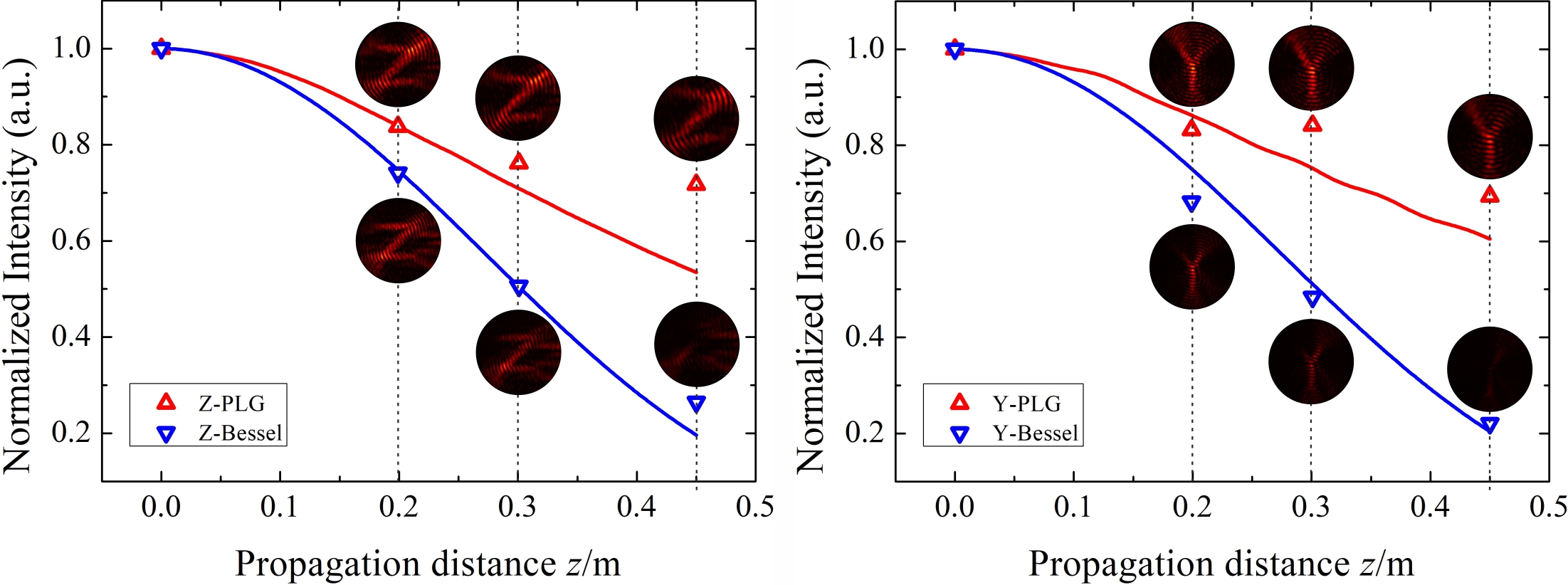
The summation of each beam’s intensity in the central region around the desired curve in Fig. 5(e)-(h) is further calculated for quantitative comparison, as shown in Fig. 6. The corresponding theoretical simulations are also presented with solid lines. After propagating for 45 cm, the intensity of the ‘Z’-shaped customized-PLG beam attenuates to 72% of the original, while the intensity of the ‘Z’-shaped customized-Bessel beam only retains 27%. Similarly, the ‘Y’-shaped customized-PLG beam’s intensity is much higher than that of ‘Y’-shaped customized-Bessel beam under the same propagation distance.
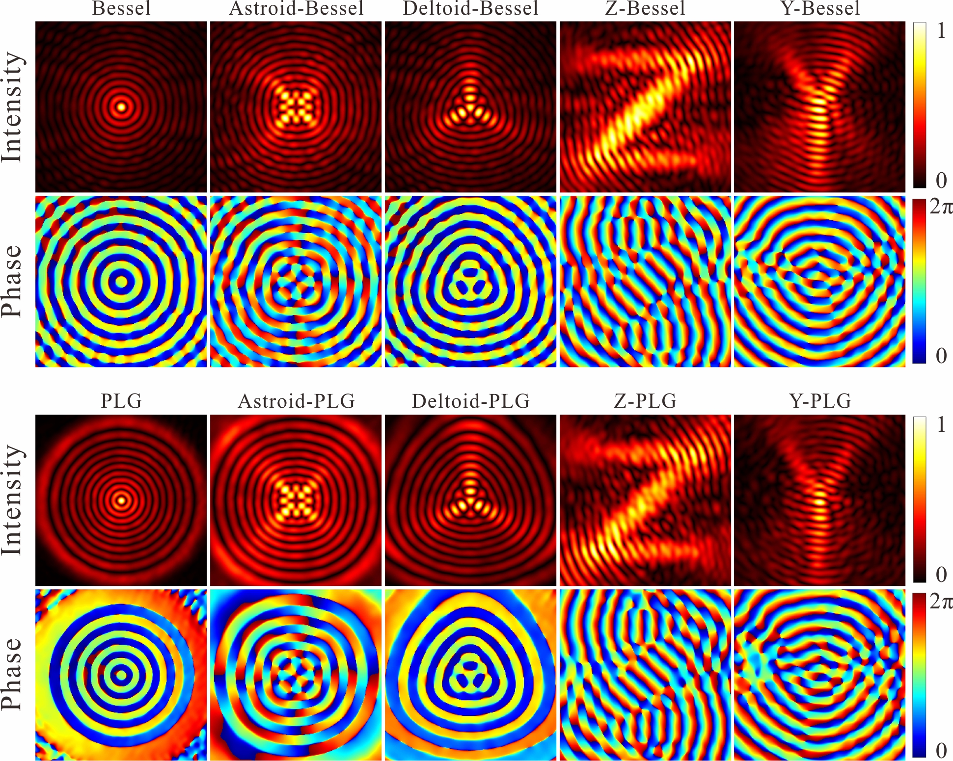
Moreover, we use a reference beam to interfere with the customized beams and record the interference patterns, then apply the holographic interferometry method Nehmetallah et al. (2015) to determine the phase distributions of the customized beams, as shown in the second and fourth columns of Fig. 7. The intensity profiles of the object beams are also reconstructed for comparison, as shown in the first and third columns of Fig. 7. All the results agree well with the theory, indicating that the generation qualities of the customized beams are very well.
IV Conclusion
In summary, we experimentally generate a series of customized-PLG beams that can present any desired high-intensity distributions. The key ingredient is based on tailoring the angular spectrum of the PLG beam by an algebraic function, which is constructed using the ‘Bessel-pencil’ method. We also generate some non-diffraction caustic beams that possess the same intensity profiles with the customized-PLG beams for comparison. The results show that the customized-PLG beams can maintain their profiles and suffer less energy loss than the non-diffraction caustic beams and hence can propagate a longer distance. The phase structures of all the generated beams are also determined by the holographic interferometry method, which agrees well with the theory and further validates the generation quality of the customized beams. This new phyletic structure beam could find broad applications in areas such as optical communication, spatial soliton control, optical tweezing and trapping, atom optics, etc.
Funding
This work is supported by National Natural Science Foundation of China (NSFC) (12104358, 92050103, 11534008, 12033007, and 61875205).
References
- Rubinsztein-Dunlop et al. (2016) H. Rubinsztein-Dunlop, A. Forbes, M. V. Berry, M. R. Dennis, D. L. Andrews, M. Mansuripur, C. Denz, C. Alpmann, P. Banzer, T. Bauer, et al., J. Opt. 19, 013001 (2016).
- Forbes et al. (2021) A. Forbes, M. de Oliveira, and M. R. Dennis, Nat. Photonics 15, 253 (2021).
- Hansen et al. (2016) A. Hansen, J. T. Schultz, and N. P. Bigelow, Optica 3, 355 (2016).
- Baumgartl et al. (2008) J. Baumgartl, M. Mazilu, and K. Dholakia, Nat. photonics 2, 675 (2008).
- Vettenburg et al. (2014) T. Vettenburg, H. I. Dalgarno, J. Nylk, C. Coll-Lladó, D. E. Ferrier, T. Čižmár, F. J. Gunn-Moore, and K. Dholakia, Nat. methods 11, 541 (2014).
- Torres (2012) J. P. Torres, Nat. Photonics 6, 420 (2012).
- Wang et al. (2021) C. Wang, Y. Yu, Y. Chen, M. Cao, J. Wang, X. Yang, S. Qiu, D. Wei, H. Gao, and F. Li, Quantum Sci. Technol. 6, 045008 (2021).
- Chen et al. (2021) Y. Chen, J. Wang, C. Wang, S. Zhang, M. Cao, S. Franke-Arnold, H. Gao, and F. Li, Opt. Express 29, 31582 (2021).
- Abramochkin and Volostnikov (2010) E. G. Abramochkin and V. G. Volostnikov, Phys. Wave Phen. 18, 14 (2010).
- Wang et al. (2016) Y. Wang, Y. Chen, Y. Zhang, H. Chen, and S. Yu, J. Opt. 18, 055001 (2016).
- Allen et al. (1999) L. Allen, M. Padgett, and M. Babiker, Progress in optics 39, 291 (1999).
- Bandres and Gutiérrez-Vega (2004) M. A. Bandres and J. C. Gutiérrez-Vega, Opt. Lett. 29, 144 (2004).
- Yu et al. (2021) Y. Yu, Y. Chen, C. Wang, J. Wang, Z. Sun, M. Cao, H. Gao, and F. Li, Opt. Lett. 46, 1021 (2021).
- Durnin et al. (1987) J. Durnin, J. J. Miceli, and J. H. Eberly, Phys. Rev. Lett. 58, 1499 (1987).
- Mendoza-Hernández et al. (2015) J. Mendoza-Hernández, M. L. Arroyo-Carrasco, M. D. Iturbe-Castillo, and S. Chávez-Cerda, Opt. Lett. 40, 3739 (2015).
- Gutiérrez-Vega and Bandres (2005) J. C. Gutiérrez-Vega and M. A. Bandres, JOSA A 22, 289 (2005).
- Mendoza-Hernández et al. (2020) J. Mendoza-Hernández, M. Hidalgo-Aguirre, A. I. Ladino, and D. Lopez-Mago, Opt. Lett. 45, 5197 (2020).
- Liu et al. (2021) X. Liu, Y. E. Monfared, R. Pan, P. Ma, Y. Cai, and C. Liang, Appl. Phys. Lett. 119, 021105 (2021).
- Sanchez-Serrano et al. (2012) P. A. Sanchez-Serrano, D. Wong-Campos, S. Lopez-Aguayo, and J. C. Gutiérrez-Vega, Opt. Lett. 37, 5040 (2012).
- López-Aguayo et al. (2010) S. López-Aguayo, Y. V. Kartashov, V. A. Vysloukh, and L. Torner, Phys. Rev. Lett. 105, 013902 (2010).
- Wang et al. (2022) C. Wang, Y. Chen, Z. Jiang, Y. Yu, M. Cao, D. Wei, H. Gao, and F. Li, Front. Phys. 17, 1 (2022).
- Martínez-Herrera et al. (2019) A. F. Martínez-Herrera, A. Céspedes-Mota, and S. Lopez-Aguayo, J. Opt. Soc. Am. A 36, 1968 (2019).
- Zannotti et al. (2020) A. Zannotti, C. Denz, M. A. Alonso, and M. R. Dennis, Nat. Commun. 11, 3597 (2020).
- Mendoza-Hernández (2021) J. Mendoza-Hernández, Opt. Lett. 46, 5232 (2021).
- Martinez-Castellanos and Gutiérrez-Vega (2015) I. Martinez-Castellanos and J. C. Gutiérrez-Vega, Opt. Lett. 40, 1764 (2015).
- Mendoza-Hernández et al. (2019) J. Mendoza-Hernández, M. Szatkowski, M. F. Ferrer-Garcia, J. C. Gutiérrez-Vega, and D. Lopez-Mago, Opt. Express 27, 26155 (2019).
- Durnin (1987) J. Durnin, J. Opt. Soc. Am. A 4, 651 (1987).
- Nehmetallah et al. (2015) G. T. Nehmetallah, R. Aylo, and L. Williams, Analog and Digital Holography with MATLAB (SPIE, 2015).
Appendix A Influence of the radial index p on the propagation property of customized PLG beam
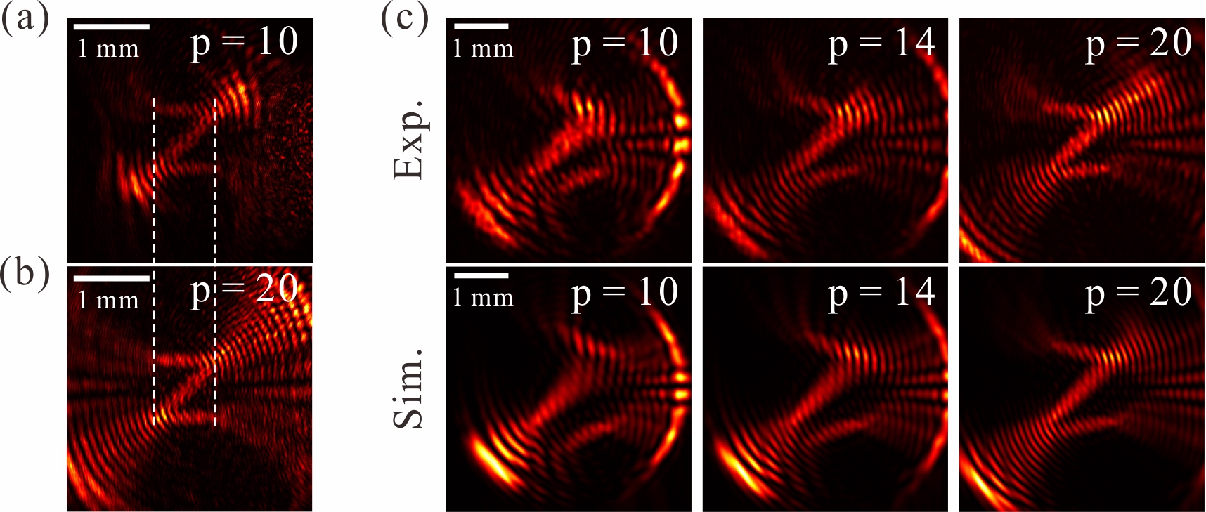
The beam waist of a seed-PLG in Eq. 4 is =. After Fourier transformed by a lens, the beam waist of the corresponding PLG beam () is inversely proportional to . The perfect diffraction distance of this PLG beam satisfies Mendoza-Hernández et al. (2020). Hence for a given and , the larger the radial index , the longer the propagation distance of the PLG beam. As we have mentioned in the manuscript, the customized-PLG beam inherits the spatial structure characteristic as well as the propagation property of the PLG beam. Therefore a large is a prerequisite for the shape-preserving propagation of the customized-PLG beam. Meanwhile, large would bring more ‘sidebands’ to the customized-PLG beam without changing the desired high-intensity curve contained therein (see Fig. 8(a) and 8(b)). In Fig. 8(c), the intensity profiles of ‘z’-shaped PLG beams for , , and at a propagation distance of 35 cm are shown for comparison, it’s clearly that the larger the , the better the shape preservation of the beam.