A high angular resolution interferometric backscatter meter
Abstract
Backscatter limits many interferometric measurements, including gravitational wave detectors, by creating spurious interference. We describe an experimental method to directly and quantitatively measure the backscatter interference. We derive and verify experimentally a relation between backscatter interference, beam radius and the scattering sample bidirectional reflectance distribution function. We also demonstrate that our method is able to measure backscatter from high quality optics for angles as low as with a angular resolution.
1 Introduction
Scattered light is a limitation for many high sensitivity interferometric measurements. In particular it is an issue in gravitational wave detectors such as LIGO and Virgo, which are km scale Fabry-Perot Michelson interferometers with power and signal recycling [1, 2]. Scattered light affect these detectors in two ways: by introducing optical loss that lowers the optical power and reduces the efficiency of quantum noise reduction through squeezing [3]; and by introducing spurious interference between backscattered light and the main interferometer beam [4]. The latter has been a limitation in sensitivity for all interferometric gravitational wave detectors operated to date and introduces non-stationary non-Gaussian noise [5, 6, 7, 8]. This is due to the extreme sensitivity of these detectors where a fraction of the main beam recombining after a spurious beam path can significantly affect the sensitivity.
This highlights the importance of understanding backscattered light, i.e. light that leaves the main interferometer beam path, propagates to a scattering surface and then back-propagates to recombine coherently with the main interferometer beam. In particular light backscattered at angles of a few mrad is relevant for beam expanding telescopes [9], and at angles between and a few degrees is relevant for core optics baffles [4]. Scattering at these small angles is rarely measured and hard to access by available methods [3].
The angular distribution of light reflected and back-scattered by a surface is usually characterized by the bidirectional reflectance distribution function (BRDF). The BRDF is usually measured by directly detecting the scattered light power using a photo-detector or a camera, and varying the relative orientation of the sensor and the scattering sample relative to the probe light beam. These systems can reach a sensitivity of and an angular resolution of with up to 15 orders magnitude of dynamic range [10, 11, 12]. With similar systems scattered light can also be imaged with lower angular resolution to identify individual point defects contributing to scattering [13, 14, 15]. However in most cases these systems cannot study light that is backscattered directly in the direction of the incoming beam. Direct backscatter measurement can easily be limited by the scattering from the measurement setup reaching only sensitivities of [16].
In this paper we present a backscatter measurement that relies on laser interference and position modulation of the scattering sample under consideration. A similar approach, but with a more complex modulation approach and poorer angular resolution, has been used for scattered light measurements for the future space borne LISA gravitational wave detector [17]. An alternative that uses a wide spectrum light source [18] has achieved a good angular resolution but two orders of magnitude poorer sensitivity.
2 Measurement setup
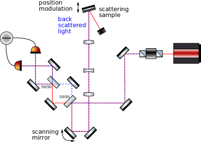
The measurement optical layout is shown schematically in figure 1. A single mode S-polarized Nd:YAG laser beam with wavelength and power is split using a 50/50 beam-splitter located at the beam waist. The beam transmitted by the beam splitter is used as a local oscillator beam for the balanced homodyne detection (BHD), while the reflected beam is sent to the scattering sample. The incident beam is translated across the surface of the scattering sample using a motorized mirror (Newport AG-M100N). The beam propagating towards the scattering sample is expanded from a waist of to using a telescope composed of three lenses. The last two lenses of focal length -100 mm and 400 mm compose a Galilean telescope with magnification . The first lens of 500 mm focal length is a relay, which adds a degree of freedom to simultaneously obtain a collimated beam and to transform the angular displacement of the motorized mirror into pure beam translation on the scattering sample. As a result for lateral beam translations of the changes of beam tilt on the sample are smaller than
Backscattered light propagates back through the telescope towards the first 50/50 beam splitter, where half of the power is sent towards the BHD and the other half is lost. The difference in power received by the two photodectors yields a signal
| (1) |
where is the power provided by the laser, is the fraction of light backscattered by the sample that is mode matched with the local oscillator beam and is the displacement of the sample.
This signal can be normalized by the total power received by the two photodiodes, which yields
| (2) |
For the case where fluctuates over many wavelength the backscattered light fraction is simply obtained as the normalized signal variance . Note that this assumes that the backscattered light is perfectly aligned and mode matched with the local oscillator beam of the BHD.
To achieve a large position modulation the sample is placed on a breadboard suspended on four metal wires at degrees angle to the vertical, similarly to a Newton’s cradle. This allows a free pendulum motion along the beam axis, while restricting the motion in the orthogonal plane. After a gentle touch the free motion of that suspension creates a decaying sinusoidal motion with an amplitude of a few hundred wavelengths and quality factor . The motion Doppler shifts the backscattered light frequency and create a quasi sinusoidal signal with a time dependent frequency proportional to the instantaneous bench speed. This results in a signal with a power spectrum spreading between and a few kHz, with a peak power just below the cut-off frequency as shown in figure 2. As the sample is the only object with a large motion, the up-conversion clearly identifies light that is back reflected or backscattered by the sample.
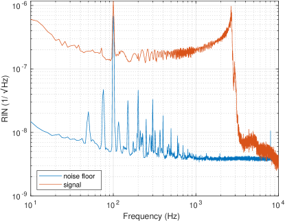
Above 500 Hz the noise floor is shot noise limited, while below there are significant contributions of the mechanical resonances of the various optical components used in the measurement and 50 Hz mains AC current harmonics. To measure without being affected by these noise sources we integrate the power spectrum density of only between 500 Hz and 6 kHz, which yields a variance measurement with negligible bias as long as the peak emission is between 2 kHz and 5 kHz.
This measurement is affected by speckle, that is by the particular random realization of the light that is backscattered. Hence the measured quantity is an exponentially distributed random variable. This random effect can be averaged by scanning the scattering sample in translation, with each translation by a beam radius yielding an independent measurement [17]. We scan the target surface with aid of the motorized mirror using 49 dedicated points on the surface spanning over an area of 7x7 beam radii. This yields a measurement of the average scattering with statistical errors. This inherently assumes that the target scattering is uniform over the scanned surface. This is a good assumption for rough surfaces however for higher quality optics localized scratches or dust particles can yield high scattering for some pointings. To mitigated this we use a median of the 49 measurements corrected by a factor to obtain a robust measurement of the exponential distribution parameter.
3 Relation between and BRDF
In the previous section we have described how the scattered light fraction can be measured using a BHD. This is the quantity of interest when evaluating the impact of scattered light on gravitational wave detectors or other interferometric measurements. However, scattered light of a given object is usually characterized using its BRDF. In this section we will derive a simple analytical relation between these two quantities.
A normalized gaussian beam with radius and wavefront radius of curvature has the following form in cylindrical coordinates
| (3) |
We mean by normalized that . For a point scatterer the light close to the optical axis at large distance can be approximated by a normalized spherical wave
| (4) |
The overlap integral of these two fields will yield the interference between a Gaussian beam and a spherical wave, i.e. a perfect scatterer.
| Overlap | (5) | ||||
| (6) | |||||
| (7) |
This expression can be further approximated by evaluating it in the Gaussian beam far field, i.e. assuming that is many Rayleigh ranges from the beam waist of radius at position .
| (8) |
where is the Gaussian beam radius at the position of the spherical wave emission.
Hence the overlap between a Gaussian beam and backscattered light depends only on the size of the beam at the scattering surface. Although this was derived for a point scattering source centered on the beam axis, it remains true if the scattering is due to a large number of uniformly distributed point sources or due to random roughness of the surface. We will not derive this more general relation, but verify it experimentally in section 4.
A normalized spherical wave is equivalent to a BRDF of , where is the incidence angle on the scattering object. Hence for a scattering object the backscattered light fraction is simply obtained by replacing the spherical wave BRDF by the BRDF of the sample object
| (9) |
4 Results
We have performed measurements using the setup described in section 2. The alignment of the backscattered field with the local oscillator beam has been verified using a flat mirror instead of the scattering target shown in figure 1. The directly back-reflected beam has interference visibility of 88%, while the maximum that is attainable is 94% given that half of the retro-reflected light is lost and sent back towards the laser. The measured backscatter fraction below is corrected for this interference visibility loss.
4.1 Backscatter as a function of beam radius
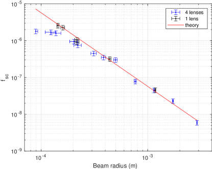
To verify the relation between backscatter fraction and BRDF we have measured the backscattering from a PTFE target (integrating sphere plug) as a function of beam size. PTFE is a near perfect volume Lambertian diffuser that scatters light in both polarizations with ideally a [19]. The beam radius was measured with a CCD camera and fitted with a Gaussian beam independently in the horizontal and vertical direction. The root-mean-square of the horizontal and vertical radius is used as the beam radius in the results below.
The beam at the output of the telescope described in section 2 was converged with a focal length lens to a waist of and the target placed at different locations to vary the beam size by more than one order of magnitude. The measured backscatter fraction is shown in figure 3 and matches well the theoretical expectation of equation 9 for beam radii above , but it is a factor 2-3 smaller close to the beam waist. This may be due to aberration in the beam converged using a single plano-convex lens. To verify this instead of four lenses we used a single focal length lens and a shorter optical path length. This configuration shows an excellent match at all radii down to the waist of .
These results confirm the relation given by equation (9).
4.2 Backscatter as a function of incidence angle
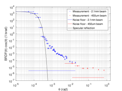
The backscatter as a function of incidence angle was measured for a multi-band () anti-reflective coated vacuum window. The coating has been measured to have a 700 ppm reflectivity at for 0 degree incidence angle. The 0.5 degree wedge of the window was placed vertically, and the incidence angle changed horizontally to measure at small angles the backscatter from only one of the two surfaces. The measured is converted into BRDF using equation (9).
The measurement result is shown in figure 4. Below the tails of the Gaussian beam specular reflection are dominant as the beam provided by the telescope has a divergence. The angular errors are due to the quadratic sum of beam incidence angle variation during the sample surface scan and the positioning error provided by the window kinematic mount micrometer (Newport HR-13). Note that within 1 m of the beam waist the Gaussian beam wavefront curvature is essentially flat, inducing negligible angular changes of less than across the beam radius.
At angles larger than 10 mrad the optical configuration was changed by removing the diverging lens from the optical path to obtain a smaller beam radius of and a times larger signal above the measurement noise floor. However this introduces a much larger angular error as in that case the motorized mirror motion no longer preserves the incidence angle on the sample.
For angles between 1 mrad and 10 mrad the BRDF is proportional to , which is typical for polished optics [9, 3]. While at angles larger than 50 mrad the BRDF becomes approximately independent of the incidence angle, this transition occurs at a smaller angle compared to uncoated or high reflective coated optics because the term is strongly reduced by the anti-reflective coating [20, 21].
5 Conclusion
We have proposed and implemented an interferometric measurement of backscattered light that uses relatively simple and readily available components. In a simplified case we have derived the relation between the backscattered light fraction, the Gaussian beam radius and the sample BRDF. This relation was verified experimentally using the proposed setup.
The measurement setup achieved a angular resolution limited by beam divergence and measures backscatter for incidence angles larger than . In particular it is able to measure backscatter at angles of a few mrad that are relevant for beam expanding telescope lenses in gravitational wave detectors. This allows to measure the scattering of coated optics, which depends on the surface roughness and defects, but also on the scattering reduction due to the anti-reflective coating that depends on how well the coating follows the bare optic surface.
This method can be further expanded to increase the telescope magnification by a factor 10 to reach a beam radius of . This should allow to measure backscatter for angles larger than with resolution, and cover angles of to measure the most critical scattering from gravitational wave detectors core optics. As translating a large beam by several waist becomes increasingly impractical, the speckle can be instead averaged by changing the beam tilt by several beam divergence angles, for instance in a circle at fixed incidence with respect to the sample surface.
Acknowledgements The Virgo document number of this paper is VIR-0111A-22. \bmsectionData Availability Statement Data underlying the results presented in this paper are not publicly available at this time but may be obtained from the authors upon reasonable request. \bmsectionDisclosures The authors declare no conflicts of interest.
References
- [1] J. Aasi et al., \JournalTitleClass. Quantum Grav. 32, 074001 (2015).
- [2] F. Acernese et al., \JournalTitleClass. Quantum Grav. 32, 024001 (2015).
- [3] Y. Drori, J. Eichholz, T. Edo, H. Yamamoto, Y. Enomoto, G. Venugopalan, K. Arai, and R. X. Adhikari, “Scattering loss in precision metrology due to mirror roughness,” arXiv:2201.05640 (2022).
- [4] J.-Y. Vinet, V. Brisson, S. Braccini, I. Ferrante, L. Pinard, F. Bondu, and E. Tournié, \JournalTitlePhysical Review D 56, 6085 (1997).
- [5] K. L. Dooley et al., \JournalTitleClass. Quantum Grav. 33, 075009 (2016).
- [6] S. Soni et al., \JournalTitleClass. Quantum Grav. 38, 025016 (2021).
- [7] A. Longo, S. Bianchi, W. Plastino, N. Arnaud, A. Chiummo, I. Fiori, B. Swinkels, and M. Was, \JournalTitleClass. Quantum Grav. 37, 145011 (2020).
- [8] M. Was, R. Gouaty, and R. Bonnand, \JournalTitleClass. Quantum Grav. 38 (2021).
- [9] B. Canuel, E. Genin, G. Vajente, and J. Marque, \JournalTitleOptics Express 21, 10546 (2013).
- [10] NIST, “Bidirectional optical scattering facility,” https://www.nist.gov/laboratories/tools-instruments/bidirectional-optical-scattering-facility.
- [11] Fraunhofer Institute for Applied Optics and Precision Engineering, “Light scattering measurement systems in the VIS, UV, und IR spectral ranges,” https://www.iof.fraunhofer.de/en/competences/coating-and-surface-functionalization/surface-and-thin-film-characterization/scattered-light-measurement-analysis/light-scattering-measurement-systems-vis-uv-ir.html.
- [12] T. Labardens, P. Chavel, Y. Sortais, M. Hébert, L. Simonot, A. Rabal, and G. Obein, \JournalTitleElectronic Imaging 2021, 140 (2021).
- [13] F. Magaña-Sandoval, R. X. Adhikari, V. Frolov, J. Harms, J. Lee, S. Sankar, P. R. Saulson, and J. R. Smith, \JournalTitleJournal of the Optical Society of America A 29, 1722 (2012).
- [14] D. Vander-Hyde, C. Amra, M. Lequime, F. Magaña-Sandoval, J. R. Smith, and M. Zerrad, \JournalTitleClassical and Quantum Gravity 32, 135019 (2015).
- [15] A. Kontos, B. Loglia, B. King, and N. Dziubelski, \JournalTitleOptics Express 29, 44012 (2021).
- [16] S. Zeidler, T. Akutsu, Y. Torii, and Y. Aso, \JournalTitleOptics Express 27, 16890 (2019).
- [17] V. Khodnevych, S. D. Pace, J.-Y. Vinet, N. Dinu-Jaeger, and M. Lintz, “Study of the coherent perturbation of a michelson interferometer due to the return from a scattering surface,” in Proc. SPIE 11180, International Conference on Space Optics — ICSO 2018, N. Karafolas, Z. Sodnik, and B. Cugny, eds. (SPIE, 2019).
- [18] I. Khan, M. Lequime, M. Zerrad, and C. Amra, \JournalTitlePhysical Review Applied 16, 044055 (2021).
- [19] A. Bhandari, B. Hamre, Ø. Frette, L. Zhao, J. J. Stamnes, and M. Kildemo, \JournalTitleApplied Optics 50, 2431 (2011).
- [20] C. Amra, G. Albrand, and P. Roche, \JournalTitleApplied Optics 25, 2695 (1986).
- [21] G. Soriano, M. Zerrad, and C. Amra, \JournalTitleOptics Letters 44, 4455 (2019).