Polar Coded Modulation via Hybrid Bit Labeling
Abstract
Bit-interleaved coded modulation (BICM) and multilevel coded modulation (MLC) are commonly used to combine polar codes with high order modulation. While BICM benefits from simple design and the separation of coding and modulation, MLC shows better performance under successive-cancellation decoding. In this paper we propose a hybrid polar coded modulation scheme that lies between BICM and MLC, wherein a fraction of bits are assigned to set-partition (SP) labeling and the remaining bits are assigned for Gray labeling. The SP labeled bits undergo sequential demodulation, using iterative demodulation and polar decoding similar to MLC, whereas the Gray labeled bits are first demodulated in parallel and then sent for decoding similar to BICM. Either polar codes or other channel codes (such as LDPC codes) can be used for the Gray labeled bits. For length 2048 rate 1/2 polar code on 256-QAM, the performance gap between BICM (Gray labeling only) and MLC (SP labeling only) can be almost fully closed by the hybrid scheme. Notably, the hybrid scheme has a significant latency advantage over MLC. These performance gains make the proposed scheme attractive for future communication systems such as 6G.
Index Terms:
coding theory, polar codes, coded modulationI Introduction
Polar codes, pioneered by Erdal Arıkan[1], are the first family of error-correcting codes that provably achieve capacity for a wide range of channels, with low encoding and decoding complexity. At short block lengths, concatenated with cyclic redundancy check (CRC) outer codes, polar codes under successive cancellation list decoding [2] show competitive, and in some cases, better performance as compared with turbo and LDPC codes [3]. Thus polar codes were adopted as the error correcting code for control channels in the fifth generation (5G) wireless communications standard [4].
To achieve higher spectrum efficiency required by the next generation wireless networks, it is essential to combine polar coding with high order modulation. Two commonly used schemes that combine polar code with channel modulation are bit-interleaved coded modulation (BICM) [5, 6], and multilevel coded modulation (MLC) [7, 8].
In bit-interleaved polar coded modulation (BI-PCM) [9], polar coding and modulation are connected by an interleaver, and Gray labeling is commonly used for mapping between the coded bits and the constellation symbols. At the receiver, on a constellation with symbols, the demodulator computes the soft information for all bits of each received symbols in parallel, which are then de-interleaved and passed to the polar decoder. In BI-PCM, the -ary channel is effectively decomposed into binary sub-channels, and decoded regardless of their dependency. Benefits from its easiness of code design and the separation of coding and modulation, BI-PCM has been adopted for polar code in the 5G wireless communication standard [10]. For constellation whose order is not a power of 2, an additional polarization matrix can be used to connect polar codes with channel modulation [11]. However, the major drawback of BICM is that it is unable to achieve the constellation-constrained capacity over additive white Gaussian noise (AWGN) channels [5], due to loss of mutual information between the decomposed sub-channels.
It is known that MLC together with multi-stage decoding (MSD) can achieve the constellation constrained capacity over AWGN channels, provided that the code rate of each level is properly designed [8]. It turns out that MSD is very similar to successive cancellation (SC) decoding of polar code on the conceptual level. Seidl et al. [9] first discuss the multilevel polar coded modulation (ML-PCM). They introduce a channel parition framework that unifies both the bit channel formation arise with SC decoding, and the channel decomposition in MSD. This framework makes it possible to assign the code rate, and design the polar code at each level of ML-PCM in a consistent way. In ML-PCM on a constellation with symbols, the -ary channel is decomposed into binary sub-channels preserving their dependency. At the receiver, a multi-stage demodulator sequentially computes the soft information of those sub-channels for each symbol. At each level, the computation is based on both the channel output and the hard values of all the previous sub-channels, where the hard values are obtained from the polar decoder. In this way, the mutual information between the sub-channels is preserved, and ML-PCM is expected to have a better performance compared with BI-PCM over AWGN channels.
However, there are multiple rounds of information exchanges between the demodulator and the decoder during its multi-stage decoding process in ML-PCM. At each level, the demodulator needs to send the evaluated soft information for a certain sub-channel over all received symbols to the decoder, and wait for the hard values from the decoder to proceed to the next stage. This frequent communication could introduce considerable latency for the ML-PCM receiver. To mitigate this latency issue, we introduce a hyrbid polar coded modulation design that lies between ML-PCM and BI-PCM, that is able to reduce the amount of communication between the demodulator and the decoder, while still maintaining a considerable performance gain over BI-PCM.
I-A Our Contribution
In this paper we propose a new polar coded modulation scheme, referred as hybrid polar coded modulation (Hybrid-PCM) hereafter, that can be viewed as a comprehensive framework having both BI-PCM and ML-PCM as its special cases. In our Hybrid-PCM scheme, the -ary channel on a constellation with symbols is decomposed into binary sub-channels following a new channel transform that we refer as hybrid binary partition. This channel transform has an integer-valued splitting parameter that lies between 0 and . At the receiver side, the demodulator computes the soft information for the the first sub-channels sequentially, based on both the channel output and the hard value of their previous sub-channels. Then with the hard information of the first levels, the demodulator estimates the rest of the sub-channels parallelly regardless of their dependency. Vaguely speaking, out of those levels for every received symbol, the first levels are sequentially decoded similar to ML-PCM, and the last levels are parallelly decoded similar to BI-PCM. In this way, only the mutual information of the first sub-channels is preserved during the decoding process, and we are free to choose this splitting parameter between and . We also propose a hybrid labeling rule to fit our scheme. This labeling rule lies between Gray labeling, commonly used in BICM, and set-partitioning (SP) labeling, commonly used in MLC, and it’s governed by the same splitting parameter .
If we choose to be equal to 0, then our hybrid scheme becomes BI-PCM. And if we choose to be , our hybrid scheme becomes ML-PCM. For lying between 0 and , our hybrid scheme can reduce the amount of back-and-forth communication required in ML-PCM, while as we will show in Section V, still holding a considerable performance gain over BI-PCM.
II Preliminaries
In this section, we describe our system model, and give a brief review on the concepts of polar codes and polar coded modulation. This prepare us for the development of our proposed hybrid polar coded modulation scheme.
Here are some notation conventions that we follow throughout this paper. We use bold letters like to denote vectors, and non-bold letters like to denote symbols within that vector. For , we denote its subvector consists of symbols with indices from to as . And we use to denote the concatenation of vector and vector .
II-A System Model
In this paper, we consider memoryless AWGN channels with quadrature amplitude modulation (QAM) and pulse-amplitude modulation (PAM). Since any -QAM constellation can be constructed from two independent -PAM constellations for the I-channel and Q-channel, henceforth we regard every QAM symbol as two independent PAM symbols.
For a PAM constellation with symbols, its signal points are given by Each symbol in the constellation is labeled by a binary -tuple, and we say that symbols in this constellation have bit levels. The input-output relation of the AWGN channel is given by , with for each channel use, and being a zero mean Gaussian noise with standard deviation . The quality of the channel is measured by the signal to noise ratio (SNR):
II-B Polar Codes
Assuming , an polar code is a binary linear block code generated by rows of the polar transformation matrix , where
and is the -th Kronecker power of . The encoding scheme is given by , where is a length- binary input vector carrying data bits, and is the codeword for transmission. The positions of the data bits in are specified by an information index set of size , with the rest of the bits in frozen to certain fixed values, usually zeros. The construction for polar codes usually refers to the selection of the information index set .
II-C Bit-Interleaved Polar Coded Modulation (BI-PCM)
Let , and let denotes the number of channel uses. In BI-PCM, the binary codeword generated by the polar encoder is permuted by an interleaver. Then, each block of bits is mapped into a constellation symbol in for channel transmission. At the receiver’s side of BI-PCM, for each received symbol, the demodulator ignores the relation between bit levels, and computes the soft information for all bit levels solely based on the channel observation.
Let be a -ary channel with input symbol set with , and output alphabet . In a BI-PCM scheme over this channel, is decomposed into binary sub-channels that are viewed as independent channels by the receiver. This channel transform is called parallel binary partition (PBP) in [9]. Here we denote it as
where denotes the binary sub-channel for the -th bit level for . In PBP, each sub-channel only has the knowledge of the channel output . And Gray labeling is commonly used to generate sub-channels that are as independent as possible [12]. Let the bit-to-symbol labeling rule given by , then has the transition probability
for .
After demodulation, as shown in Figure 1 (left), the soft information of all bits is de-interleaved, and fed to the decoder. Note that to use a single polar decoder for BI-PCM, the order of the constellation has to be a power of 2.
II-D Compound Polar Code
In BI-PCM, to handle constellation whose order is not necessarily a power of 2, compound polar code is proposed in [11] that uses an additional polarization matrix to connect polar code with channel modulation. This structure is also mentioned in [9, Sec.V.D], and later used in [13] on 64-QAM.
In BI-PCM with compound polar code, the -ary channel is also decomposed into binary sub-channels following PBP, but the decomposed channels are not decoded in parallel. In compound polar code, an polarization matrix is used to further polarize those decomposed sub-channels. And on the receiver’s side, the polarized channels are decoded sequentially based on the hard information of their previous channels. For the details of compound polar code, we refer the readers to [11].
With this additional polarization matrix, compound polar code shows better performance compared with plain BI-PCM under SC decoding [11]. It inherits the benefit that demodulation and decoding are separated just like plain BI-PCM, but it also introduces extra decoding latency due to that additional polarization matrix. Since in this paper, we focus on reducing the iterative communication between the demodulator and the decoder in ML-PCM, we also include compound polar code in our simulation comparison in Section IV.
For our simulation in Section IV, we use as the additional polarization matrix for 8-PAM the same as in [11, Sec.VII.A], and use as the additional polarization matrix for 16-PAM the same as in [9, Sec.V.D]:
It has been shown in [14] that for the labeling in BI-PCM with compound polar code, the least significant bit Binary Reflected Gray Code (LSB-BRGC) shows a better performance compared with the Binary Reflected Gray Code (BRGC) under SC decoding. Thus we also adopt LSB-BRGC for the bit labeling for BI-PCM with compound polar code in our simulation.
II-E Multilevel Polar Coded Modulation (ML-PCM)
Let be the symbol set of a constellation of order , and let denotes the number of channel uses. In a ML-PCM scheme, there are component polar codes, each of length . For encoding, a length binary vector carrying both the data bits and the frozen bits is split into vectors of equal length, and encoded by those component polar codes respectively. Let denote the encoder output of the -th component polar code for . The modulator then map the -tuple into a constellation symbol for transmission for . In such a way, each component polar code only appears at a corresponding single bit level for every channel use.
At the receiver’s side of ML-PCM, a multi-stage demodulator computes the soft information for those bit levels sequentially, based on both the received symbols, and the hard values of the previous bit levels. More specifically, as shown in Figure 1 (right), at stage of the decoding process, the demodulator computes the soft information of the -th bit level for every received symbols, and send it to the -th polar decoder. Then, the demodulator waits for -th decoder to send back its decoding result. After retrieving the hard values for the -th bit level of every received symbol, the demodulator then proceeds to the next bit level.
Let be a -ary channel with input symbol set with , and output alphabet . In a ML-PCM scheme over this channel, is effectively decomposed into binary sub-channels preserving their mutual information. This channel decomposition is called sequential binary partition (SBP) in [9], here we denote it as
where denotes the binary sub-channel for the -th bit level for . In SBP, each sub-channel has the knowledge of both the channel output , and their previous bit levels. And set-partitioning (SP) labeling is commonly used to generate widely separated bit level capacities [9]. Let the bit-to-symbol mapping rule given by , then has the transition probability
for .
III A Hybrid Scheme for Polar Coded Modulation
In this section, we propose a hybrid polar-coded modulation scheme that lies between BI-PCM and ML-PCM. Our hybrid scheme can be viewed as a comprehensive framework that has BI-PCM and ML-PCM as its two special cases. We begin by introducing a channel decomposition that we refer as hybrid binary partition.
III-A Hybrid Binary Partitions
Let be a discrete memoryless channel with input symbol set with , and output symbol set . We define the hybrid binary partition (HBP) with splitting parameter as the channel transform
where is an integer between 0 and , and denotes the decomposed binary sub-channel for the -th bit level for . In this channel decomposition, the first sub-channels have the knowledge of their previous bit levels and the rest of the sub-channels only have the knowledge of the first bit levels.
Formally, for , we have
with transition probability
And for , we have
with transition probability
Following this definition, the first sub-channels in HBP with splitting parameter will be the same as the first sub-channels in SBP on the same -ary channel .
We make the remark that for a given -ary channel , HBP with splitting parameter will be the same as PBP, and HBP with splitting parameter will be the same as SBP. Therefore, PBP and SBP can be viewed as two special cases of HBP.
III-B Hybrid Labeling
In polar coded modulation schemes, PBP in BI-PCM is commonly equipped with Gray labeling, and SBP in ML-PCM is commonly equipped with SP labeling [9]. Since HBP is a hybrid channel transform that stands between PBP and SBP, we propose to equip it with a hybrid labeling rule that stands between Gray labeling and SP labeling.
Let be the symbol set for a -ary constellation, we describe our hybrid labeling rule with splitting parameter as follows:
-
1.
For every symbol , the first bit levels are labeled the same as the SP labeling rule.
-
2.
For the rest of the bit levels, we first partition into subsets, such that symbols within each subset have the same bits on their first bit levels. Then for each subset , we label the rest of the bit levels for symbols in following the Gray labeling rule for the sub-constellation .
Example 1.
We illustrate this hybrid labeling rule by taking the 16-PAM constellation as an example. Figure 2 shows examples of three labeling rules for 16-PAM, with Gray labeling at the top, SP labeling in the middle, and hybrid labeling with splitting parameter at the bottom.
Denote the symbol set by . In the hybrid labeling with splitting parameter , the first two bit levels for every are labeled the same as in SP labeling. Then can be partitioned into four subsets according to the first two bit levels:
Those four subsets are colored differently in Figure 2. Take for example, in the hybrid labeling, the last two bit levels for the symbols in are labeled following the Gray labeling rule viewing as a 4-PAM constellation.
III-C Hybrid Polar Coded Modulation (Hybrid-PCM)
Now we describe our hybrid coded modulation scheme. Let be the symbol set of a constellation of order , and let denotes the number of channel uses. In our Hybrid-PCM with splitting parameter , the -ary channel is decomposed by HBP with splitting parameter into binary sub-channels, where each of the first sub-channels corresponds to a component polar code of length , and the last sub-channels correspond to a single component code of length .
For encoding, a length binary vector carrying both the data and the frozen bits is split into length- vectors and one single vector of length . Those sub-vectors are encoded by the component codes respectively. Denote by the encoder output of the -th component polar code for , and denote by
the encoder output of the -th component code, where is a length- vector for . The modulator then map the -tuple
into a constellation symbol for transmission for .
At the receiver’s sided of Hybrid-PCM, as shown in Figure 3, a multi-stage decoder first computes the soft information for the first bit levels sequentially, based on both the received symbols, and the hard values of the previous bit levels. Then the demodulator computes the soft information for the rest of the bit levels in parallel, based on the received symbols, and the hard values of the first bit levels. The soft information for the last bit levels is then de-interleaved, and then fed to the decoder for the last component code. In our hybrid scheme, we employ the hybrid labeling rule with the same splitting paramete for the mapping between the coded bits and the constellation symbols.
Note that for a -ary channel , this hybrid scheme with the splitting parameter can be viewed as a general framework that includes both BI-PCM and ML-PCM as special cases by setting and , respectively.
IV Performance Evaluation
We present some simulation results of our hybrid scheme on 64-QAM and 256-QAM where all polar codes are constructed following the Monte Carlo construction.
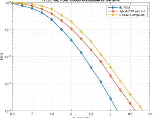
Figure 4 shows the simulation results of SC decoding for polar coded modulation on 64-QAM with three difference schemes: ML-PCM, Hybrid-PCM with splitting parameter , and BI-PCM with compound polar code. In our experiment, every 64-QAM is simulated by two independent 8-PAM symbols, and all the coded modulation schemes are applied on the 8-PAM constellation. We can observe that ML-PCM performs better than Hybrid-PCM, and BI-PCM with compound polar code as expected, and our hybrid scheme with splitting parameter shows an approximated 0.5 dB performance gain over BI-PCM with compound polar code.
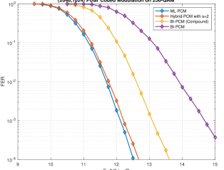
Figure 5 shows the simulation results of SC decoding for polar coded modulation on 256-QAM with four difference schemes: ML-PCM, Hybrid-PCM with splitting parameter , BI-PCM with compound polar code, and plain BI-PCM (Figure 1). In our experiment, every 256-QAM is simulated by two independent 16-PAM symbols, and all the coded modulation schemes are applied on the 16-PAM constellation. We can see that our hybrid scheme with splitting parameter can close up majority of the performance gain of ML-PCM over BI-PCM with compound polar code, while reducing the number of required iterative information exchanges between the demodulator and the decoder in ML-PCM by half, thus reducing the overall decoding latency.
V Conclusion and Discussion
We have proposed a new polar coded modulation scheme that uses hybrid bit partitions by assigning only a fraction of bits for sequential binary partition and subsequent iterative demodulation and decoding, whereas the remaining bits are subject to parallel binary partition and corresponding parallel demodulation and then decoding. It can be viewed as a comprehensive framework that includes both ML-PCM and BI-PCM as special cases, and our simulation results have shown that it can alleviate the latency in ML-PCM while still maintaining a considerable performance gain over BI-PCM.
Although we only discussed polar codes as component codes for our hybrid coded modulation, in principle, just like MLC and BICM, any other codes such as Turbo or LDPC codes can also be chosen as component codes in our hybrid scheme. The flexibility of working together with other codes, reduced latency compared to ML-PCM, and the large performance gain over BI-PCM on high order modulation make the proposed hybrid polar coded modulation scheme attractive for future communication systems such as 6G.
References
- [1] E. Arikan, “Channel polarization: A method for constructing capacity-achieving codes for symmetric binary-input memoryless channels,” IEEE Transactions on information Theory, vol. 55, no. 7, pp. 3051–3073, 2009.
- [2] I. Tal and A. Vardy, “List decoding of polar codes,” IEEE Transactions on Information Theory, vol. 61, no. 5, pp. 2213–2226, 2015.
- [3] M. C. Coşkun, G. Durisi, T. Jerkovits, G. Liva, W. Ryan, B. Stein, and F. Steiner, “Efficient error-correcting codes in the short blocklength regime,” Physical Communication, vol. 34, pp. 66–79, 2019.
- [4] 3GPP TSG RAN WG1 Meeting #87, Final report, Reno, NV, November 2016.
- [5] G. Caire, G. Taricco, and E. Biglieri, “Bit-interleaved coded modulation,” IEEE transactions on information theory, vol. 44, no. 3, pp. 927–946, 1998.
- [6] A. G. i Fabregas, A. Martinez, and G. Caire, “Bit-interleaved coded modulation,” 2008.
- [7] H. Imai and S. Hirakawa, “A new multilevel coding method using error-correcting codes,” IEEE Transactions on Information Theory, vol. 23, no. 3, pp. 371–377, 1977.
- [8] U. Wachsmann, R. F. Fischer, and J. B. Huber, “Multilevel codes: Theoretical concepts and practical design rules,” IEEE Transactions on Information Theory, vol. 45, no. 5, pp. 1361–1391, 1999.
- [9] M. Seidl, A. Schenk, C. Stierstorfer, and J. B. Huber, “Polar-coded modulation,” IEEE Transactions on Communications, vol. 61, no. 10, pp. 4108–4119, 2013.
- [10] V. Bioglio, C. Condo, and I. Land, “Design of polar codes in 5g new radio,” IEEE Communications Surveys & Tutorials, vol. 23, no. 1, pp. 29–40, 2020.
- [11] H. Mahdavifar, M. El-Khamy, J. Lee, and I. Kang, “Polar coding for bit-interleaved coded modulation,” IEEE Transactions on Vehicular Technology, vol. 65, no. 5, pp. 3115–3127, 2015.
- [12] C. Stierstorfer and R. F. Fischer, “(gray) mappings for bit-interleaved coded modulation,” in 2007 IEEE 65th Vehicular Technology Conference-VTC2007-Spring. IEEE, 2007, pp. 1703–1707.
- [13] K. Chen, K. Niu, and J.-R. Lin, “An efficient design of bit-interleaved polar coded modulation,” in 2013 IEEE 24th Annual International Symposium on Personal, Indoor, and Mobile Radio Communications (PIMRC). IEEE, 2013, pp. 693–697.
- [14] G. Bocherer, T. Prinz, P. Yuan, and F. Steiner, “Efficient polar code construction for higher-order modulation,” in 2017 IEEE Wireless Communications and Networking Conference Workshops (WCNCW). IEEE, 2017, pp. 1–6.