Tombo Propeller: Bio-Inspired Deformable Structure toward Collision-Accommodated Control for Drones
Abstract
There is a growing need for vertical take-off and landing vehicles, including drones, which are safe to use and can adapt to collisions. The risks of damage by collision, to humans, obstacles in the environment, and drones themselves, are significant. This has prompted a search into nature for a highly resilient structure that can inform a design of propellers to reduce those risks and enhance safety. Inspired by the flexibility and resilience of dragonfly wings, we propose a novel design for a biomimetic drone propeller called Tombo propeller. Here, we report on the design and fabrication process of this biomimetic propeller that can accommodate collisions and recover quickly, while maintaining sufficient thrust force to hover and fly. We describe the development of an aerodynamic model and experiments conducted to investigate performance characteristics for various configurations of the propeller morphology, and related properties, such as generated thrust force, thrust force deviation, collision force, recovery time, lift-to-drag ratio, and noise. Finally, we design and showcase a control strategy for a drone equipped with Tombo propellers that collides in mid-air with an obstacle and recovers from collision continuing flying. The results show that the maximum collision force generated by the proposed Tombo propeller is less than two-thirds that of a traditional rigid propeller, which suggests the concrete possibility to employ deformable propellers for drones flying in a cluttered environment. This research can contribute to morphological design of flying vehicles for agile and resilient performance.
Index Terms:
deformable propeller, collision-accommodated, biomimetic design, soft robotics, drones’ safetyI Introduction
Drones such as popular VTOL (vertical take-off and landing) have brought enormous benefits to humans operating in various sectors, providing military, civilian, and commercial applications, including monitoring, inspection, logistics, transportation, and entertainment. Due to their compact dimension and flight agility in small spaces, drones have been attracting interest from both academia and industry with the potential of large market [1]. Several projects were launched to harness the potential of drones in industry, such as Prime Air (Amazon - 2013), Wing (Alphabet 2014), DRONES (FedEx - 2018), FarmBeats (Microsoft in partnership with DJI - 2015), Aquila (Facebook - 2014), Skylink (IBM - 2016), and others. One of the primary concerns in the operation of drones is the risk of injury to humans or damage to property-both objects in the environment and the drone itself, which may occur during flight or in event of a collision. In such a scenario, a drone could seriously harm a human or significantly damage something and drop and crash due to damaged propellers. With that in mind, many technologies promoting the safety of drones have been introduced, such as safety cages for drones (hardware), and vision-based obstacle-avoiding algorithms (intelligence). While the former increases the size and physical load of a drone, the latter increases the computational load on its central processor, resulting in the trade off of high efficiency costs for safety. Nevertheless, the desire to operate drones in cluttered environments or nearby humans is growing and necessitates strategies to mitigate injuries or damages caused by unexpected collisions.
Meanwhile, in the natural world, flying insects seem to effortlessly accommodate collisions with objects in their surroundings without leaving any footprint of damage. In fact, mother nature is the greatest creator, and at the same time she is a living encyclopedia from which robotics researchers may learn invaluable knowledge and glean hints for solving engineering problems. In this paper, the dragonfly wing construction is an excellent example of shock absorption and self-recovery, due to the high flexibility of a hinge-like structure called nodus. From the perspective of soft robotics, biomimicry of such structures or functions is a key to solve the safety problem of drones.
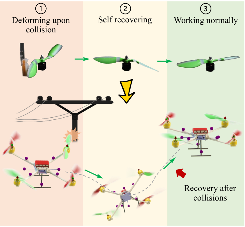
This paper presents the Tombo propeller. Without requiring the burden of a heavy physical or computational load, toward ultimate safety for drones, this biomimetic design deformable propeller can accommodate collisions while retaining sufficient rotation-thrust to remain airborne as shown in Figure 1. The key structure of the Tombo propeller is its hinge-like nodus, which is a deformable joint made of silicone and fiber tendons (see Figure 2a) bio-inspired by the function and structure of the dragonfly wing nodus. Due to the nodus mechanism, a Tombo propeller can self-recover and rotate properly within an average of 0.46 seconds upon collision, enabling the promising recovery of drones after sudden collisions with their surroundings. In addition, the hybrid design made of soft and hard parts enables the propeller to regain stiffness and generate sufficient rotation-thrust to fly the drone. Moreover, with its deformable leading edge, the Tombo propeller imparts lower impact force and damage upon collision with an object than that by a traditional drone propeller, thus further improving the safety of the propeller and struck object. The main contributions of this research are as follows:
-
1.
Proposal of a novel biomimetic design for drone propellers.
-
2.
Construction of an aerodynamic model of the Tombo propeller.
-
3.
Theoretical and experimental characterization of the Tombo propeller with different configurations of nodus.
-
4.
Proposal of a control strategy which includes collision recovery by a drone with Tombo propellers.
Compared to our previous paper [2], where we only introduced design, fabrication, and preliminary measurement of thrust force of the Tombo propeller; in this paper, we present a thorough analysis and evaluation of the propeller considering variations in its material’s composition and configuration as well as different rotational speeds. In addition, we propose a model for characterization of generated thrush force, taking into account the deformation of the Tombo propeller and its aerodynamic properties. We propose several metrics to evaluate and identify the optimal design according to the user needs. Finally, we also test the flight ability of real drone platform using the Tombo propeller, and proposed a simplified control strategy for showing the feasibility of recovery of drone after the collision.
In this paper, a concrete review of drones and related work is mentioned in Section II, followed by the biomimetic design of a 9-inch (228.6 mm) long Tombo propeller in Section III. Section IV briefly introduces a derivation of an aerodynamics model for the Tombo propeller. Section V provides details of Tombo propeller characteristic measurement experiments, which is followed by the results in Section VI. Next, Section VII presents a control strategy and showcases the flying of an embedded Tombo propeller drone. Then, is the Discussion in Section VIII and Conclusion in Section IX.
II Related Works
In this section, we focus on solutions that have been introduced to improve the safety of drones and Unmanned Aerial Vehicles (UAVs). Overall, these solutions can be classified into two groups: Collision Avoidance and Collision Impact Reduction. Details can be found below:
For collision avoidance, the following approaches have been proposed: geometric, force-field, optimized, sense and avoid [3, 4]. Here, passive sensors (monocular camera [5], depth camera [6]), active sensors (ultrasonic sensor [7], light detection and ranging [8], and radar [9]) or a combination of them [10, 11] are preferable to detect objects within the flying range. Although such cameras have a large field of view and high resolution, their associated obstacle detection algorithm is greatly affected by weather conditions, lighting, and shiny or reflective surfaces. In addition, vision sensors work best with stationary subjects, yet they are required to passively respond to high-speed moving images exceeding km/h [12] and are limited at blind spots. Moreover, sensors are needed to overcome the blind spot factor and improve the accuracy of calculation, resulting in increased weight and higher cost UAVs. Recently, event cameras have been applied to UAVs with promising results in terms of avoiding fast-moving obstacles [13]. However, the event camera has a heavier weight, larger size, and higher noise than a standard one at the same resolution. Furthermore, the high noise of an event camera reduces its accuracy at large distances, limiting the reliable detection range to m.
Regarding collision impact reduction, solutions to protect the actuators (rotors) from collisions, or facilitate recovery after a collision require additional features. In most cases, a cage [14, 15, 16, 17] is employed due to low cost, low profile, and simple setup; for instance, protective cages shielding motors and preventing multi-directional concurrences. However, their bulky structure may inversely bring a higher risk of collision, and they greatly increase the drone weight thus reducing the flight time. As an alternative approach, foldable structures [18, 19] could help UAVs decrease their dimension and risk of crashing, especially when flying through a narrow gap. Another exciting approach combines rigid guards and soft, deformable mechanisms to reduce crash impact, absorb collision shock, and retain resilience [20, 21, 22, 23]. However, such integration may require a complex control strategy and high resource consumption in practical scenarios. Recently, the notion of a flexible blade [24] has gained attention since this structure may enable propellers to deform and recover upon collision without any additional mechanism. Nonetheless, a flexible blade remains dangerous for soft objects such as human skin. Furthermore, large-sized thin blades experience great deformation during rotation, limiting the use of these propellers in large UAVs.
Consequently, a trade-off between the safety of UAVs and their structure and configuration exists. Therefore, despite efforts to improve the structure, integrate perception, and avoid collisions, drones and UAVs remain vulnerable to collisions because of technical limitations of sensors and unpredictable factors. This poses a great challenge, as nowadays, UAVs are becoming increasingly popular and being used for more application in complex, cluttered, or partially-known environments. Hence, there remains a big question: Is there a solution that significantly improves the safety of drones but does not largely compromise their basic design and function?
III Biomimetic Design
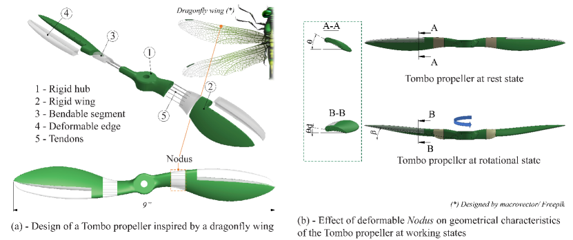
Insect wings often suffer stress due to wind gusts and collisions with the surroundings. Therefore, the insect wings evolved to adopt an anti-shock or shock-absorption structure, resulting in mitigation of wing damage upon collision. Regarding the dragonfly wing structure, one of the most important parts is the nodus, which has a one-way hinge-like structure that can passively flex upon external contact. This part allows the wing to twist, bend, or even fold without incurring damage. The natural nodus containing resilin (similar to isotropic rubber) can provide both structural reinforcement and shock absorption. These characteristics provide a hybrid structure (stiff and flexible) that both ensure aerodynamic properties when flying and reduce the risk of damage to the wing upon collision. Based on the characteristics of the dragonfly wing nodus, we propose an unprecedented deformable propeller which we named Tombo propeller (Figure 2a). The rigid parts include a hub (1) and wing (2), connected by a nodus-like bendable segment (3) made from silicon rubber and reinforced by embedded tendons (5, nylon fibers) that connect rigid parts (hub and wings). An optional deformable edge (4) can be added for rapid absorption of an impact at the time of collision. In our initial work [2], the rigid parts of the propellers were made of ABS (Acrylonitrile Butadiene Styrene) using FFF (fused filament fabrication)-based 3D printing which creates a layered structure, which eventually reduces the strength among layers upon lateral impact. Therefore, in this work we propose a novel generation model, the rigid parts are fabricated by injection molding as commercial rigid propellers to enhance the concreteness of the Tombo propeller. To enhance the propeller surface quality, especially the nodus-like part, molds were made of aluminum alloy fabricated by machining instead of ABS fabricated by 3D printing. The fabrication process for a Tombo propeller has been described [2].
Nodus mechanical property and performance strongly affects the working ability of the proposed propeller. As illustrated in Figure 2, when the propeller rotates, there is a decrease in pitch angle theta, which is due to the inherent propeller’s deformation. This negatively affects thrust force generation since it depends largely on the pitch angle. In addition, the softness of the nodus may influence the working stability of a drone equipped with Tombo propellers. Therefore, in this research, we investigate various configurations of the nodus structure and materials (silicone rubber embedded with monofilament nylon fibers), i.e. the morphology, to determine an optimum construction of the Tombo propeller.
IV Aerodynamic model of Tombo propeller
Previous research has indicated that aerodynamic parameters such as drag and thrust forces [25, 26, 27], blade flapping [26, 28], and so on, strongly affect the flight characteristics of drones. Control approaches for drones require consideration to aerodynamic parameters to attain stability during dynamic flight or hovering [29]. Therefore, in developing an aerodynamics model of the Tombo propeller, mechanical properties play an important role for its application to standard UAVs.
IV-A Revisit of Aerodynamic Model of a Classical Propeller
Aerodynamic models of standard propellers and quadrotors have been established and well developed [30, 31, 32]. The most important factors of aerodynamic parameters, the forces, including the normal force (), tangential force (), lift force (), and drag force () (see Figure 3e) can be calculated as
| (1) |
where is the designed span length function along the airfoils; is the air density; is rotational speed; is the aerodynamics force coefficient function (see [33]) and is the designed pitch angle function (Figure 3e); is the designed boundary surface function; is the span length element along the airfoils.
IV-B The Role of Deformable Angles
Although the flexibility of the nodus saves the propeller from collision damage, it creates unexpected deformation when the propeller rotates. In detail, when a rotor is rotating, rigid wing (Figure 3d) displacement is quantitatively specified by bending angles , and twist angle as depicted in Figure 3d. These deformable angles alter the geometry of the propeller, such as pitch angle , inducing change in aerodynamic forces and . Therefore, an aerodynamic model Tombo propeller needs to factor in the deformable angles of the nodus in order to achieve efficient operation of the device.
IV-C Nodus Modelling
To determine the deformable angles, we model both material and structure, i.e. morphology, of the nodus using the combination of composite model and beam model.
IV-C1 Material Modelling
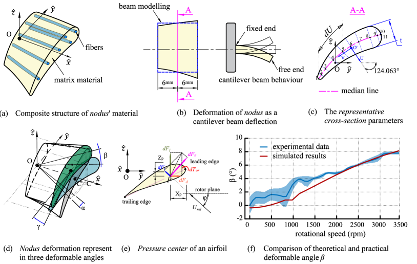
The structure of the nodus suggests a composite model of silicone rubber and a tendon play the roles of material matrix and reinforced fibers, respectively (see Figure 3a). Based on research by Younes et al. on different models for composite modelling [34], we chose the Chamis model for modelling because of its high accuracy for predicting elastic modulus coefficients in many matrix and fiber material cases. According to the Chamis model, Young modulus and the shear modulus of nodus are defined as below:
| (2) |
where is the fiber volume fraction; and are the Young modulus and shear modulus of the matrix material, respectively; and are the Young modulus and shear modulus of the fiber material in turn. The fiber volume fraction (from to ), measured as the percentage of fiber area in the composite cross-section, dominates the mechanical properties of the nodus. Changing the number of fibers or their diameter adjusts fiber volume fraction , resulting in a proportional change in nodus stiffness.
IV-C2 Structure Modelling
We hypothesized that the nodus deflects obeying cantilever beam behavior with one fixed end (see Figure 3b) during its rotation. Therefore, the deformable angles can be defined in a model of a stationary cantilever (at a specific rotation speed) by applying the beam modelling. As a result, bending angles in plane and in plane of a Tombo propeller are defined based on [35] as follows:
| (3) |
where , are forces from the wing applied to the nodus; is the nodus length; is the Young modulus of the nodus; and are the inertial moments of the cross-section of the nodus in , directions, respectively. Since the inertial moments depend on the cross-section position, Eq. 3 shows a strong relationship between nodus length and the cross-section position to deformable angles and .
IV-C3 Hybrid Modelling
To model the mechanical characteristics of the nodus, we used hybrid modelling combining insights of both aforementioned material and structural models. However, both popular composite models reviewed in [34] and the beam model [35] often required high homogeneity of materials and a standard cross-section area structure; while the nodus has different directions of nylon tendons and varying morphology along its body. Therefore, for ease of modeling, we proposed a representative cross-section (Figure 3c), stay at the middle of the nodus (section A-A) to overcome this issue. This particular cross-section will be used for all related calculations of the nodus. The twist angle of a Tombo propeller can be defined as a form of elongated cross-section as below [36]:
| (4) |
where , is the infinitesimal length along the camberline line; is the applied torque generated by the aerodynamic forces and ; and are the area and the length of a camberline of the representative cross-section; are the length of the nodus; is the thickness normal to the median line. If we call P is the center of pressure at the quarter-chord point of the airfoil [31, 37] (see Figure 3e). The applied torque element can be defines as below.
| (5) |
with , , , and are the coordinates of leading edge and trailing edge of the representative cross-section in and directions respectively.
IV-D Aerodynamic Model of Tombo Propeller
At a rotational speed, we assumed the deformable propeller morphology was unchanged. Therefore, the applied aerodynamic forces of a Tombo propeller can be calculated as in Eq. 1. Note that the optional deformable edge (4) of the Tombo propeller was assumed not to deform in our proposed aerodynamic model at rotational speed. Thus, the influence of the deformable edge is negligible in the computational model. Here, functions of the span length, aerodynamic force coefficient, and the boundary surface were considered to be the main contributors to the deformable angles. In the model, the aerodynamic forces consist of three components generated by the hub, the nodus so these aerodynamic forces can be explained as below:
| (6) |
The hub is rigid and the nodus length is about 10 of that of the propeller so we can use Eq. 1 to calculate both and . The aerodynamic force of the wing [31] for the Tombo propeller needs to take into account the contribution of the deformable angles as below.
| (7) |
where is the deformable span length function along the airfoils; with (x) is the deformable pitch angle function of the Tombo propeller airfoil; is the deformable boundary surface function; and can be defined by the projections of the wing into the direction and plane respectively when nodus deforms. Note that the wing posture can be defined by rotation matrix using a roll-pitch-yaw sequence of rotations around axes of a fixed reference frame [38]:
| (8) |
where , are the bending angle functions of the nodus on , ; is the twist angle around the centroid contour along the nodus; , , and are the rotations around the , , and axes of the fixed reference frame (see Figure 3d), respectively.
To simplify change in boundary surface function, we project this wing into three original planes , , and . Finally, we obtained the equation of aerodynamic forces applied to a wing as below:
| (9) |
where and are radius of innermost and outermost curvatures from the position of nodus onward; , are the designed geometrical functions of the leading edge and the trailing edge, respectively.
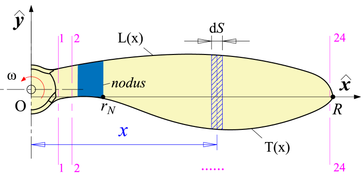
To define functions , we represent half of a propeller by 24 cross-sections along the span (Figure 4) by SolidWorks 2020 software. In each Section we collected the angle of attack and the coordinates of leading edges and trailing edges by AutoCad 2022 software. Next, we applied the formula of , , and as functions of span length using polyfit function of Matlab R2020b.
IV-E Numerical Implementation of the Aerodynamic Model
By its nature, the proposed model has an implicit problem because of the inter-dependencies between the input parameters. Non-linear solution techniques can solve this problem, but using a simple algorithm where an iteration loop is used until convergence is reached is a more practical solution. Algorithms 1 and 2 have shown this approach in two cases: a classical propeller (the rigid one) and a Tombo propeller (see https://github.com/Ho-lab-jaist/tombo-propeller.git for more details).
V Measurement of Tombo Propeller’s Characteristics
In this section, we describe indoor experiments with different configurations of nodus matrix materials and fiber diameters (see Table I) to determine the characteristics of Tombo propellers. These experiments were performed for the following purposes:
-
1.
To evaluate the aerodynamic model proposed in IV based on the thrust force and deformation angle results.
-
2.
To observe characteristics of the Tombo propeller in action to acquire and build fundamental knowledge on this biomimetic propeller.
| Name | Nodus’ configuration | Deformable edge materials | Size (inch) | |||||||||||||||
|---|---|---|---|---|---|---|---|---|---|---|---|---|---|---|---|---|---|---|
| Matrix material |
|
|
|
|
|
|
||||||||||||
| Conf. 0 | - | - | - | - | - | - | - | - | 9 | |||||||||
| Conf. 1 | DragonSkin 10 | Nylon 6 | 6 | 0.94 | 12 | 0.1542 | 0.0551 | - | 9 | |||||||||
| Conf. 2 | DragonSkin 20 | Nylon 6 | 6 | 0.94 | 12 | 0.5705 | 0.2036 | - | 9 | |||||||||
| Conf. 3 | DragonSkin 30 | Nylon 6 | 6 | 0.94 | 12 | 0.7873 | 0.2809 | - | 9 | |||||||||
| Conf. 4 | DragonSkin 30 | Nylon 6 | 6 | 0.38 | 12 | 0.6557 | 0.2341 | - | 9 | |||||||||
| Conf. 5 | DragonSkin 10 | Nylon 6 | 5 | 0.5 | 12 | 0.1315 | 0.0469 | DragonSkin 10 | 9 | |||||||||
| Conf. 6 | DragonSkin 10 | Nylon 6 | 5 | 0.75 | 12 | 0.1413 | 0.0505 | DragonSkin 10 | 9 | |||||||||
| Conf. 7 | DragonSkin 10 | Nylon 6 | 5 | 0.9 | 12 | 0.148 | 0.0528 | DragonSkin 10 | 9 | |||||||||
| Conf. 8 | DragonSkin 20 | Nylon 6 | 5 | 0.5 | 12 | 0.4862 | 0.1736 | DragonSkin 20 | 9 | |||||||||
| Conf. 9 | DragonSkin 20 | Nylon 6 | 5 | 0.75 | 12 | 0.5227 | 0.1866 | DragonSkin 20 | 9 | |||||||||
| Conf. 10 | DragonSkin 20 | Nylon 6 | 5 | 0.9 | 12 | 0.5473 | 0.1954 | DragonSkin 20 | 9 | |||||||||
| Conf. 11 | DragonSkin 30 | Nylon 6 | 5 | 0.5 | 12 | 0.671 | 0.2396 | DragonSkin 30 | 9 | |||||||||
| Conf. 12 | DragonSkin 30 | Nylon 6 | 5 | 0.75 | 12 | 0.7213 | 0.2574 | DragonSkin 30 | 9 | |||||||||
| Conf. 13 | DragonSkin 30 | Nylon 6 | 5 | 0.9 | 12 | 0.7552 | 0.2695 | DragonSkin 30 | 9 | |||||||||
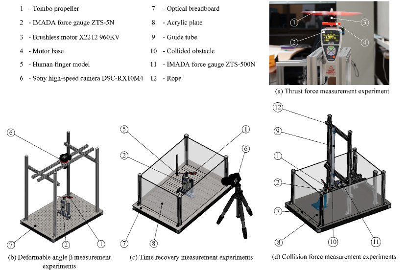
The experiment apparatus included: an X2212 KV motor (to rotate the propeller) fed by a V power source, which was mounted on a force gauge (IMADA ZTS-5N 10Hz, Japan); an acrylic base plate to isolate the conductor and other parts (section V-A; a high-speed camera (DSC-RX10M4, Sony, Japan) to record recovery time and deformable angle measurements (sections V-C and V-D)); lighting and a black background to facilitate visual detection. The results of the experiments are presented and discussed in Section VI.
V-A Thrust Force Measurement Experiments
In this experiment, we measured the thrust force of the Tombo propeller with reference to the rotational speed through the range to rpm with configurations, as shown in Table I. The experiment was conducted indoors, and the axis of the motor was set vertical relative to the ground (see Figure 5a). The measurement sampling rate was Hz.
V-B Deformable Angle Measurement Experiments
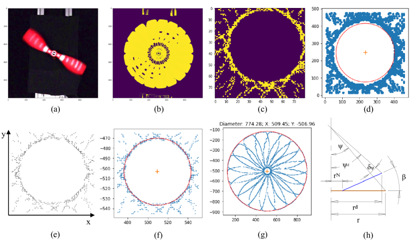
For this measurement, the high-speed camera ( fps) was set perpendicular to the rotor plane and coincident with the rotor axis as shown in Figure 5d. The camera distance and light source intensity were adjusted to obtain good quality images.
Initially, we increased the speed of the rotor to a specific rotation speed, then we started recording and reduced the rotor speed to rpm. The recorded video was processed by OpenCV in Python and split into a series of still image frames, which appeared blurred (Figure 6a). Next, we determined the rotational speed of the Tombo propeller in each image frame and the corresponding propeller diameter using a normalized 10-continuous-frame combo (Figure 6b).To determine the propeller diameter at each combo, we needed to focus on the center of its rotation (Figure 6c). Center detection initially attempted using OpenCV function was poor because the generated coordinate must be an integer (Figure 6d). We then transformed the coordinates of each pixel to the real field (Figure 6e). From that, we utilized a RANdom SAmple Consensus (RANSAC) [39] algorithm to determine the appropriate center of a point cloud (Figure 6f). We then could define the diameter of a -continuous-frame combo taking advantage of Hull’s contour (Figure 6g). Finally, the deformable angle could be calculated based on change in diameter and the position of the nodus (Figure 6h). Note that we omitted recorded image perspective distortions made by the change of propeller tip in the vertical direction due to the small increment of the camera angle of view (less than ).
V-C Time Recovery Measurement Experiments
The objective of this experiment was to determine the recovery time of the Tombo propeller after a collision. In this experiment we used a model artificial finger made of silicone rubber (Dragon Skin 30) with a nylon mono filament core (see Figure 5b) and the high-speed camera to record the process of collision and subsequent recovery of the propeller (for both rotational speed and thrust). The propeller recovery time in terms of thrust force was calculated from measurements by both the force sensor and the camera, while that in terms of rotational speed was determined from the video data.
V-D Collision Force Measurement Experiments
For consistent measurement, the direction of the collision force must coincide with the measurement axis of the force gauge. The ZTS-500N force gauge with a large force range (up to N), and a tube ( cm in diameter, cm in length) was placed perpendicular to the motor plane (see Figure 5c). The principle of measuring the collision force was as follows. An obstacle was dropped freely inside the guide tube from the top end to collide with the propeller at a specific location, and the collision force was recorded by the force gauge.
This experiment was divided into two parts. In part 1, we determined the most dangerous crash zone on the propeller blade by colliding the object at different distances , , , , , and mm from the center of the propeller (see Table II). The position at mm from the center of the propeller was chosen to perform part 2 of the test due to its highest critical force per thickness ( N/mm). In part 2, we measured the collision force over a range of Tombo propeller configurations from Conf. 5 through Conf. 13 (see Table I). The test results are summarized in Table III.
| Collision area | I | II | III | IV | V | VI |
|---|---|---|---|---|---|---|
| Distance to the hub center (mm) | ||||||
| Maximum collision force (N) | ||||||
| Thickness of the blade (mm) | ||||||
| Force per thickness (N/mm) |
V-E Noise Measurement Experiments
Here, the experiment employed a handheld Meter MK09 Sound Lever Meter measurement device. We recorded noises of single propellers from different distances: , , , , and m. In this test, we used a rigid propeller and Tombo propellers with configurations as shown in Table I.
VI Results
VI-A Aerodynamic Model of the Tombo Propeller
VI-A1 Nodus’ Parameters
The mechanical and geometrical properties of the nodus are important parameters in construction of an aerodynamic model propeller. Note that the nodus model presented in Section IV-C requires the following parameters: length of the nodus, representative cross-section information, number of fibers, diameter of fibers (from the design), Young modulus and shear modulus of the matrix material and fiber (from experiment results based on American Society for Testing and Materials Standard - ASTM 412 Die D dumbbell specimens with the Poisson ratio was chosen as ). Finally, Young modulus and shear modulus of the nodus were calculated using Eq. 2 and updated in Table I. The results indicated that the mechanical properties of the matrix play the most critical role in calculation of Young modulus and shear modulus of the nodus. In addition, increasing the number and diameter of the fibers enhanced these moduli.
VI-A2 Tombo Aerodynamics Model
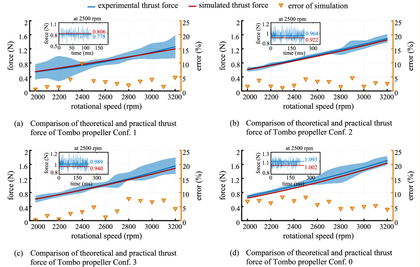
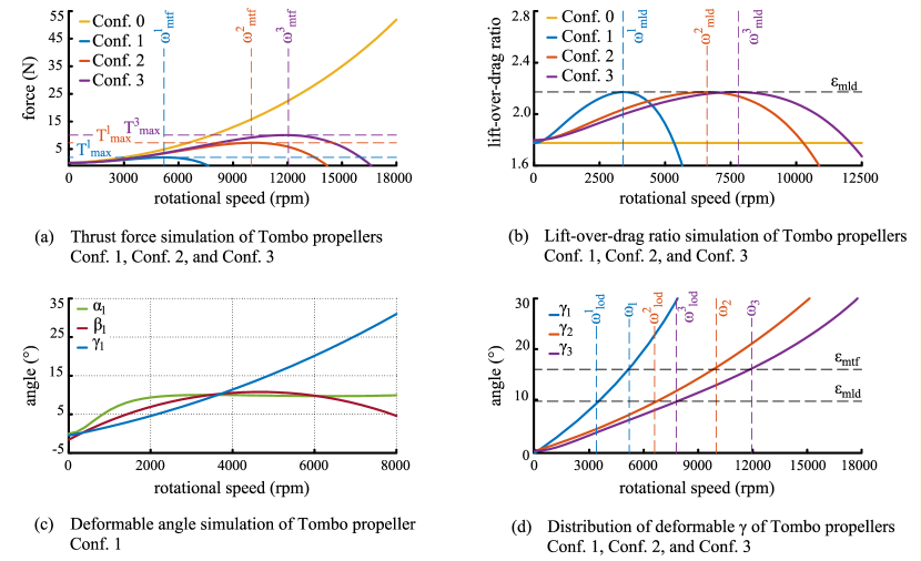
To evaluate the model, several experiments with different configurations of Tombo propeller (Table I) were conducted to compare estimated with experimental aerodynamic parameters. Figure 7 shows evaluations of thrust force in the aerodynamic model for four different configurations of Tombo propeller. First, the model showed good thrust prediction when estimation errors were less than for different degrees of nodus stiffness. Secondly, as nodus stiffness increased magnitude and stability of lift force at the same speed increased. In the experimental rotational speed range (from to rpm), the experimental and simulated thrust forces both exhibited linear characteristics, but the simulation results in a broader range (up to rpm) showed more clearly the nonlinear characteristics (see Figure 8a).
This model can help to simulate the aerodynamic parameters of the Tombo propeller over a more extensive range of rotational speed. Figure 8a shows the thrust force of rigid and Tombo propellers in the speed range below rpm. Both experimental and simulated results show that as the rotational speed gradually increased, the thrust force of Tombo propeller remained proportional to nodus stiffness, and at higher speeds a significant difference was observed. However, unlike the rigid propeller, the thrust force of each Tombo propeller configuration reached maximum at critical thrust (in steady force state only). This critical thrust depends strongly on nodus stiffness. The stiffer the nodus the higher the critical thrust force generated. The rotational speed corresponding to this critical thrust is called the maximum thrust speed, noted as . When the rotational speed surpasses , the generated thrust the generated thrust decreases rapidly. This phenomenon suggests that is a suitable choice for UAVs that need to carry heavy loads or when maximum acceleration is required.
Figure 8b shows the relationship between the lift-over-drag ratio and the rotational speed of the Tombo propeller, simulated from Eq. 1 and 7 with . For rigid propellers, independent of the rotational speed because the propeller geometry does not change during rotation. For the Tombo propeller, the coefficient varied with rotational speed. However, as in the case of maximum thrust speed, each Tombo propeller has a critical lift-over-drag ratio rotational speed where reaches the maximum (denoted ). In other words, is independent of configuration of Tombo propeller being the same for all fabrication configurations. The reason is that these configurations all have the same initial geometric design, so when deformed, these configurations, even though they differ, will interfere in the state with the highest result. This critical lift-over-drag velocity is variable between Tombo propellers and tends to increase with nodus stiffness. Therefore, can be chosen for high efficient work of UAVs such as traveling or delivery tasks.
From Equation 3 and 4 we can predict the deformable angles of the Tombo propeller. For instance, Figure 8c shows the simulation of these angles in a Conf. 1 propeller. It can be seen that as the propeller rotational speed increased, angles and increased rapidly to reach a stable value of about degrees in the speed range from rpm to rpm. Meanwhile, continued to increase rapidly showing no sign of saturation. Combined with Eq. 9 and Figure 8a, this result demonstrated the significant contribution of to the thrust force of the Tombo propeller. To confirm the simulated variation of these deformable angles, we experimented with angle using a Conf. 4 Tombo propeller (see Figure 3f). This experiment showed simulated angle was similar to the experimental angle at a rotational speed range above rpm. In the lower speed range, the observed angle changed more strongly, due to a limitation of the experimental model (see Section V-B). When the speed of the motor rotating the propeller was decelerated suddenly, the inertia force caused blade flapping at a rotational speed approaching zero, leading to a significant change in deformable angle.
To investigate the contribution of to the aerodynamic of the Tombo propeller, we simulated this angle as shown in Figure 3f. Despite different configurations, Tombo propeller which share the same original design, will reach critical thrust and critical lift-over-drag ratio states at the same and . This finding strongly confirms that plays the decisive role in the deformable states of the Tombo propeller.
VI-B Characteristics of the Tombo Propeller with Different Configurations
| Thrust force [N] |
|
Collision force [N] | Recovery time [s] |
|
|
|||||||
|---|---|---|---|---|---|---|---|---|---|---|---|---|
| Conf. 0 | – | |||||||||||
| Conf. 5 | ||||||||||||
| Conf. 6 | ||||||||||||
| Conf. 7 | ||||||||||||
| Conf. 8 | ||||||||||||
| Conf. 9 | ||||||||||||
| Conf. 10 | ||||||||||||
| Conf. 11 | ||||||||||||
| Conf. 12 | ||||||||||||
| Conf. 13 | ||||||||||||
| Mean |
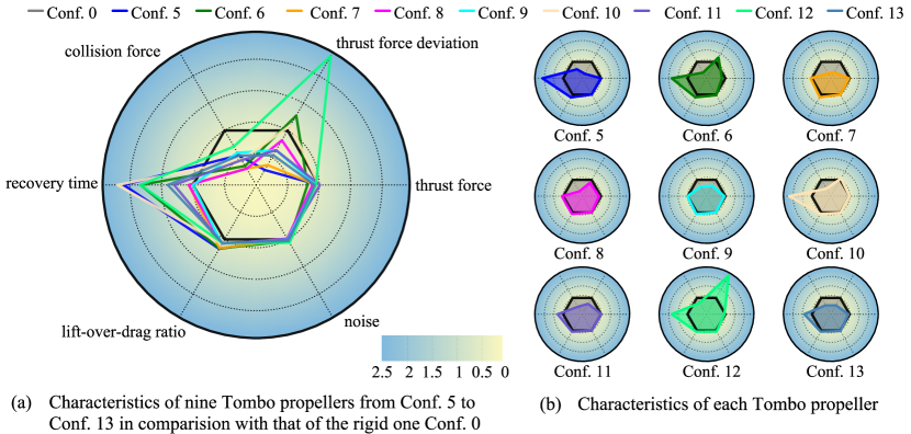
As mentioned above, the Tombo propeller is a novel propeller for UAVs, which was designed to contribute to ultimate safety. Therefore, it was important to investigate its characteristics to clarify and confirm its contributing features. Nine configurations of Tombo propeller and a rigid one were analyzed focusing on six characteristics: thrust force, thrust force deviation, collision force, recovery time, simulated lift-over-drag (L/D) ratio, and noise (Table III). All experiments were conducted at a propeller rotation speed of rpm, and data were normalized and by the results of the rigid propeller (Conf. 0) for visualization as Figure 9.
Overall, the Tombo deformable propeller shows promising characteristics compared to a rigid one. While all of thrust force, thrust force deviation, simulated L/D ratio, and noise of the experimental Tombo propellers ( N, N, , and dB, respectively) are almost the same as those of the rigid propeller ( N, N, , and dB, respectively), thrust force deviation, collision force, and time recovery, all differed. Note that although the mean of thrust force deviation of the Tombo propeller was lower than that of the rigid propeller, its distribution was extensive, ranging from to N among different configurations. Practical flights showed that thrust force deviation played a vital role in creating the balance of a drone, so the configuration needs to be considered to equip a drone. Last but not least, the collision force of the Tombo propeller was much smaller than that of the rigid propeller, resulting in lower risk of injury or damage upon collision with an obstacle in its surroundings.
VII Tombo Propeller in Practical Flights and Its Responsiveness to Mid-air Collisions
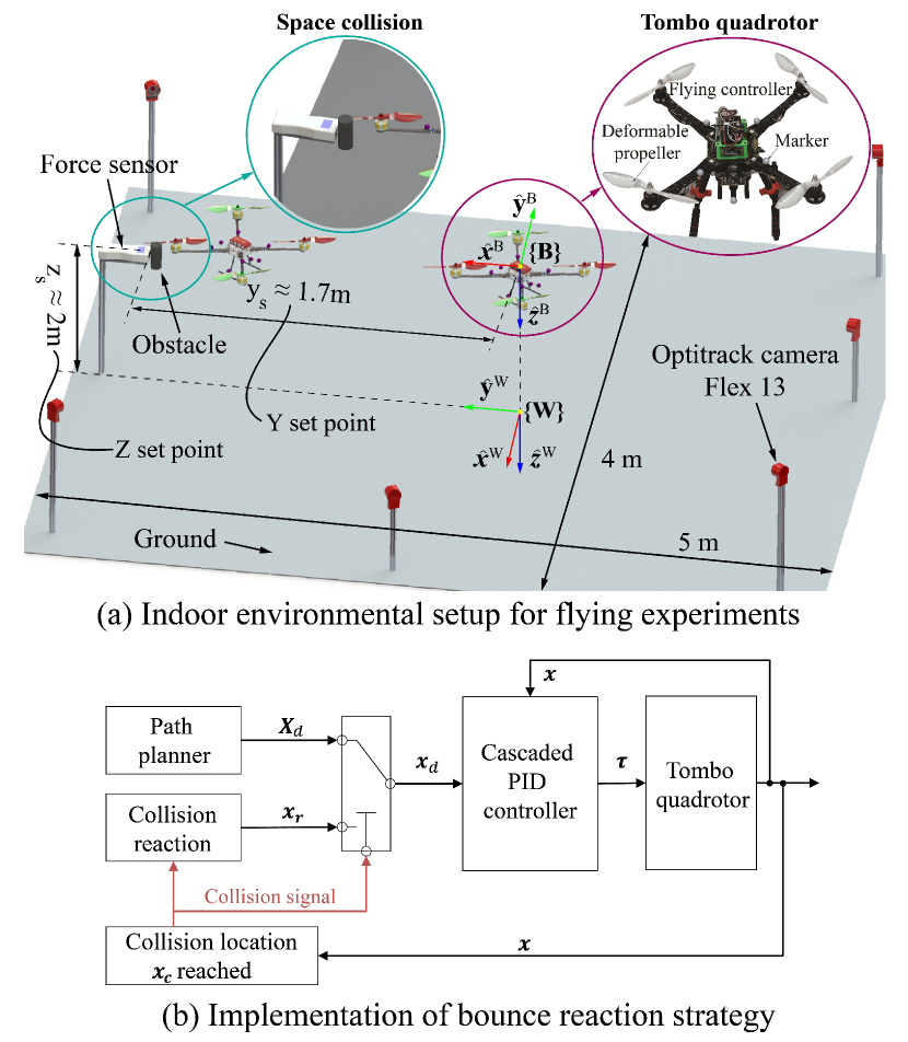
This section examines how the Tombo propellers behave in practical fight when equipped in drones (quadrotors, see Figure 10a), as well as how the controller responds during and after a collision between the Tombo drone and a fixed mid-air obstacle. We chose Tombo propellers Conf. 13 to conduct the experiments in this section because they have a low thrust deviation (see Section VI-B) and the highest stiffness of the and the deformable edge (see Table I), resulting in ease of fabrication and high consistency among fabricated propellers. Additionally, to leverage the self-recovery ability of our deformable propellers, we implemented an equilibrium bounce reaction scheme [29] which was specifically tailored to rescue the Tombo drone (quadrotor) from a sudden fall in event of propeller-obstacle collision.
VII-A Reaction Strategy
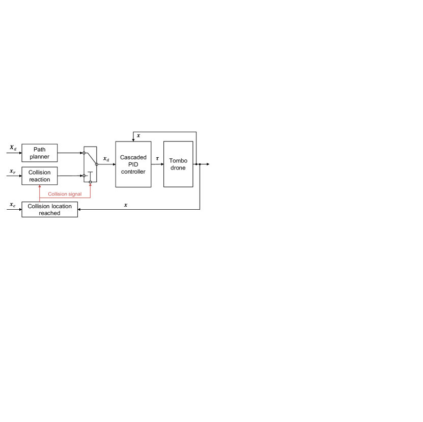
In pursuit of drone safety provided by deformable propeller recovery, we investigated an equilibrium bounce reaction strategy expected to prevent the Tombo quadrotor from falling in event of a propeller-obstacle collision. We considered a case where the quadrotor flew at designated trajectory such that one of the front propellers collided with a mid-air obstacle located at designated position with reference to the global coordinate frame (Figure 10a). Once reached; thus collision occurred, the reaction mode was immediately triggered to set the equilibrium position to , where is the bounce distance, and is the reactive normal that is opposite to the flying direction before the time of collision. This encourages the low-level controller to produce virtual forces that drive the quadrotor toward equilibrium state , and then enable stabilization of the vehicle at a safe distance from the obstacle. Since the falling rate of the quadrotor, as observed in experiments, was determined to be around m/s, and the propeller recovery time was determined to be approximately seconds, a typical PID (proportional–integral–derivative) cascaded controller could be a possible solution for low-level control. The cascaded control architecture of the quadrotor includes an outer loop P position, followed by the P angle and PID angular rate controllers, running at Hz, Hz and kHz, respectively. The equilibrium bounce reaction strategy is summarized in Figure 10b and and we open-source the implementation of the reactive control strategy using ROS (Robot Operating System) [40] as follows https://github.com/Ho-lab-jaist/tombo-propeller.git.
VII-B Experimental Setup
Figure 10a illustrates the indoor environment where the flight and collision experiments were conducted. Inside the experimental space, the custom-built quadrotor, mounted with 8 reflective markers, was precisely positioned by the OptiTrack motion capture system (mocap) including 6 tracking cameras (OptiTrack Flex 13), which provide an overall positional accuracy up to . The quadrotor’s 6-DoF pose (i.e., position and orientation), estimated by the mocap system on a desktop PC (Intel i7-7700 CPU at 3.6GHz and 8 GB RAM), was communicated to an onboard computer (Jetson TX2, NVIDIA) at around so that the automatic flight and collision reaction scheme can be practically implemented in real time, with the assistance of the PID-based low-level controller (PX4 flight stack111https://px4.io/) running on the Pixhawk 4 autopilot hardware. While the real-time postural information provided feedback signals for the P position and angle controllers, the onboard inertial measurement unit (IMU) was responsible for the most inner PID control loop of angular rate.
VII-C Results: Flying Behavior, Collision Response and Recovery
To investigate the responsiveness of the Tombo propeller and effectiveness of the bounce reaction (recovery process) scheme upon the aforementioned collision, we set up a flight test wherein the quadrotor flew along planned trajectory in direction such that the front port (left) propeller collided with an obstacle located at position m. Upon the collision, we set the bounce distance m, leading to the equilibrium position at m, for activation of the recovery process. The Tombo quadrotor, as observed from the experiments (see Figure 11), could achieve stable flights as it can track the specified reference trajectory of position during the hovering and pre-collision (flying along the -direction) phases (Figure 11c). The quadrotor started to fall when a propeller collided with the obstacle. Without application of the reaction scheme, the drone could not recover and would fall and crash (as shown in Figure 11a). In contrast, application of the bounce reaction strategy, in addition to the fast recovery of the Tombo propeller, allowed the quadrotor to stabilize in response to the collision (see Figure 11b). Figure 11c details the behavior of the quadrotor during the collision and recovery process. Specifically, once the collision occurred at around , the quadrotor oscillated and overturned with a large fluctuation in roll angle, then started to fall, which characterizes the unstable phase. However, the quadrotor did not fall to the ground (collision height 2 m). It took about to overcome the unstable phase, followed by a recovery process of about before attaining a stable state, which confirmed the responsiveness of the Tombo propeller and the effectiveness of the reaction strategy in event of collision with an obstacle. A video demonstration of the collision experiment is at: https://youtu.be/qKqtqpq_yqw.
Consequently, in this section, we confirmed the flight ability of the drone with Tombo propeller in a real platform and the recovery ability after the collision. The obtained results reveal that with minimal invasion of the classical control strategy, the drone with Tombo propeller still can perform basic flight/hovering and novel reaction upon collision with the surrounding. As a result, introduction of softness to the propeller not only decreases the risk of damage, but also does not necessarily compromise the flight ability of the drone.
VIII Discussion
VIII-A Fabrication
Integration of soft materials into a conventional propeller improved safety in the operation of drones, especially by recovery ability and risk mitigation upon collision. For mass production of the Tombo propeller, the fabrication process proposed in this research needs to be simplified. The process of embedding tendons into the matrix by gluing them into the rigid parts (hub and wing) required significant manual dexterity. This, in fact, affects the quality of the fabricated propeller, thus decreasing its durability in long-term usage. Note that, during implementation of recovery trials ( trials) in the previous section, we needed to replace the collided propeller three times, averagely one Tombo propeller may endure up to three collisions. Regarding the scalability, we have succeeded in fabrication of a wide range of Tombo propellers, such as , , , -inch long propellers, based on the proposed design and fabrication method. Smaller or bigger size and shape of the propeller will be investigated in the future.
Through evaluation experiments, we found that during rotation the entire Tombo propeller from the hub to the tip became quite stiff due to centrifugal force. Therefore, if connection between the nodus and the rigid parts is assured, the tendons used in the present design may be made redundant. In that event, the double injection method may be exploited for mass production of the Tombo propeller, since this technique can create a dependable junction between the soft and hard parts, as well as the longevity of the propeller. More elaboration on this approach will be conducted in future work.
VIII-B Flight Ability
The results obtained in experiments revealed, for the first time, successful flight performance and collision recovery behavior of a drone with a deformable propeller. However, there were some limitations in this study. The experiment trials were performed indoors, which ignores outdoor factors such as wind and weather conditions. Also, although PID controllers might achieve better performance in rigid propellers, due to the shortcomings of typical PID controllers, tracking errors in normal flight with deformable Tombo propellers were relatively large in some cases, especially in the -direction (Figure 11c), which led to different collision directions among flight trials and to various recovery behaviors (shown in the video at the link above). Also the fabricated propellers might not have yielded consistent behavior, which may have affected the controller’s operation. In fact, the results shown in this article present the most typical drone behavior in response to the critical case of collision and to provide a benchmark against reactive performance. The average falling recovery time , and the averaged maximum falling distance , were acceptable for this control strategy, considering the mid-air collision height was 2 m indoors. For higher altitudes there would more time thus a better chance for the drone to fully recover before crashing to the ground. That leaves rooms for work in future improvement of reaction control algorithms (e.g., model predictive control, impedance/admittance reactive controllers [29]) since the recovery time of the tested propellers (seconds) was shorter than the current time for falling recovery (seconds). To this end, in future work we aim to construct a comprehensive dynamics model of quadrotors that takes the aerodynamic modeling of Tombo propellers into consideration, which forms the foundation for advanced model-based interaction and tracking controllers, and also for morphological design optimization. Moreover, integration of perception to detect and avoid potential collisions is crucial to the realization of fully autonomous agile and resilient flying robots, which will be considered in future work.
VIII-C Possible Applications
The Tombo propellers are expected to be loaded on drones for reducing damage risk of obstacle-propeller collision in any direction. It also brings in the recovery chance after collision, thus mitigating risk to the drone itself and properties on the ground compared to crashing to the ground. The use of the Tombo propellers with other measurements will ultimately increase the safety of drones in tasks close to objects or humans (infra inspection, freight, and so on). We would also like to adopt this biomimetic approach for applications in other fields such as small-scaled wind power generation propellers (reducing bird-strike risk) or ship propellers (reducing entanglement with marine litter, fish-strike risk) toward sustainable solution for the nature.
IX Conclusion
In this work, we proposed the design and fabrication of a biomimetic propeller. This approach can be applied to different types of propellers (e.g. flapping wing and glider wings). The proposed aerodynamic model showed to correctly estimate the propeller parameters including thrust force and deformation angle in the plane perpendicular to the rotor plane. An examination of the characteristics of the Tombo propeller clarified the features and practicality of using this novel design for different vehicles. In addition, multiple flight experiments also demonstrated the ability of the Tombo propeller to increase drones’ resilience to collisions, while concurrently preserving its mechanical structure after the impact. In the future, we aim to enhance the aerodynamic model of the Tombo propeller taking into account the contribution of the deformable edge. Furthermore, we would like to develop a software application leveraging this aerodynamic model to automatically produce aerodynamic metrics and automatically recommend a biomimetic design for a conventional propeller as an output to the user.
Acknowledgments
This work was supported by JST SCORE project, Grant-in-aid for Scientific Research projects No. 18H01406 and 21H01287. We also thank Dr. Pho Van Nguyen for his advice on the modeling approach, Dr. David Price for his thorough proofreading of this manuscript.
References
- [1] EmergenResearch. (2020, Dec) Unmanned aerial vehicle (uav) market by product type, by wing type, by operation mode, by range, by maximum takeoff weight (mtow), by system, by application, by end-user, forecasts to 2027.
- [2] D. Q. Nguyen, G. Loianno, and V. A. Ho, “Towards design of a deformable propeller for drone safety,” in 2020 3rd IEEE International Conference on Soft Robotics (RoboSoft), 2020, pp. 464–469.
- [3] G. Chen, W. Dong, X. Sheng, X. Zhu, and H. Ding, “An active sense and avoid system for flying robots in dynamic environments,” IEEE/ASME Transactions on Mechatronics, vol. 26, no. 2, pp. 668–678, 2021.
- [4] K. N. McGuire, C. D. Wagter, K. Tuyls, H. J. Kappen, and G. C. H. E. de Croon, “Minimal navigation solution for a swarm of tiny flying robots to explore an unknown environment,” Science Robotics, vol. 4, no. 35, p. eaaw9710, 2019.
- [5] B. Herissé, T. Hamel, R. Mahony, and F.-X. Russotto, “Landing a vtol unmanned aerial vehicle on a moving platform using optical flow,” IEEE Transactions on Robotics, vol. 28, no. 1, pp. 77–89, 2012.
- [6] M. Iacono and A. Sgorbissa, “Path following and obstacle avoidance for an autonomous uav using a depth camera,” Robotics and Autonomous Systems, vol. 106, pp. 38–46, 2018.
- [7] N. Gageik, P. Benz, and S. Montenegro, “Obstacle detection and collision avoidance for a uav with complementary low-cost sensors,” IEEE Access, vol. 3, pp. 599–609, 2015.
- [8] L. González-deSantos, J. Martínez-Sánchez, H. González-Jorge, F. Navarro-Medina, and P. Arias, “Uav payload with collision mitigation for contact inspection,” Automation in Construction, vol. 115, p. 103200, 2020.
- [9] H. Li, W. Kinsner, Y. Wang, B. Palma, and A. Tay, “Airborne radar based collision detection and avoidance system for unmanned aircraft systems in a varying environment,” in 2021 IEEE International Conference on Wireless for Space and Extreme Environments (WiSEE), Cleveland, Ohio, USA, 2021, pp. 43–48.
- [10] M. C. P. Santos, C. D. Rosales, M. Sarcinelli-Filho, and R. Carelli, “A novel null-space-based uav trajectory tracking controller with collision avoidance,” IEEE/ASME Transactions on Mechatronics, vol. 22, pp. 2543–2553, 12 2017.
- [11] A. S. Huang, A. Bachrach, M. Krainin, D. Maturana, and N. Roy, Robotics Reseach, ser. Springer Tracts in Advanced Robotics. Springer, Cham, 2017, vol. 100.
- [12] S. U. Sharma and D. J. Shah, “A practical animal detection and collision avoidance system using computer vision technique,” IEEE Access, vol. 5, pp. 347–358, 2017.
- [13] D. Falanga, K. Kleber, and D. Scaramuzza, “Dynamic obstacle avoidance for quadrotors with event cameras,” Science Robotics, vol. 5, no. 40, 2020.
- [14] A. Klaptocz, A. Briod, L. Daler, J.-C. Zufferey, and D. Floreano, “Euler spring collision protection for flying robots,” in 2013 IEEE/RSJ International Conference on Intelligent Robots and Systems (IROS), Tokyo, Japan, 2013, pp. 1886–1892.
- [15] P. Kornatowski, S. Mintchev, and D. Floreano, “An origami-inspired cargo drone,” in 2017 IEEE/RSJ International Conference on Intelligent Robots and Systems (IROS), Vancouver, BC, Canada, 2017, pp. 6855–6862.
- [16] C. J. Salaan, K. Tadakuma, Y. Okada, E. Takane, K. Ohno, and S. Tadokoro, “Uav with two passive rotating hemispherical shells for physical interaction and power tethering in a complex environment,” in 2017 IEEE International Conference on Robotics and Automation (ICRA), Marina Bay Sands, Singapore, 2017, pp. 3305–3312.
- [17] A. Briod, P. Kornatowski, J.-C. Zufferey, and D. Floreano, “A collision-resilient flying robot,” Journal of Field Robotics, vol. 31, no. 4, pp. 496–509, 2014.
- [18] N. Zhao, Y. Luo, H. Deng, and Y. Shen, “The deformable quad-rotor: Design, kinematics and dynamics characterization, and flight performance validation,” in 2017 IEEE/RSJ International Conference on Intelligent Robots and Systems (IROS), Vancouver, BC, Canada, 2017, pp. 2391–2396.
- [19] D. Falanga, K. Kleber, S. Mintchev, D. Floreano, and D. Scaramuzza, “The foldable drone: A morphing quadrotor that can squeeze and fly,” IEEE Robotics and Automation Letters, vol. 4, no. 2, pp. 209–216, 2019.
- [20] S. Mintchev, S. de Rivaz, and D. Floreano, “Insect-inspired mechanical resilience for multicopters,” IEEE Robotics and Automation Letters, vol. 2, no. 3, pp. 1248–1255, 2017.
- [21] J. Shu and P. Chirarattananon, “A quadrotor with an origami-inspired protective mechanism,” IEEE Robotics and Automation Letters, vol. 4, no. 4, pp. 3820–3827, 2019.
- [22] P. Sareh, P. Chermprayong, M. Emmanuelli, H. Nadeem, and M. Kovac, “Rotorigami: A rotary origami protective system for robotic rotorcraft,” Science Robotics, vol. 3, no. 22, 2018.
- [23] Z. Liu and K. Karydis, “Toward impact-resilient quadrotor design, collision characterization and recovery control to sustain flight after collisions,” CoRR, vol. abs/2011.02061, 2020. [Online]. Available: https://arxiv.org/abs/2011.02061
- [24] J. Jang, K. Cho, and G.-H. Yang, “Design and experimental study of dragonfly-inspired flexible blade to improve safety of drones,” IEEE Robotics and Automation Letters, vol. 4, no. 4, pp. 4200–4207, 2019.
- [25] A. Mokhtari and A. Benallegue, “Dynamic feedback controller of euler angles and wind parameters estimation for a quadrotor unmanned aerial vehicle,” in IEEE International Conference on Robotics and Automation (ICRA), vol. 3, New Orleans, LA, USA, 2004, pp. 2359–2366 Vol.3.
- [26] H. Huang, G. M. Hoffmann, S. L. Waslander, and C. J. Tomlin, “Aerodynamics and control of autonomous quadrotor helicopters in aggressive maneuvering,” in 2009 IEEE International Conference on Robotics and Automation (ICRA), Kobe, Japan, 2009, pp. 3277–3282.
- [27] H.-N. Nguyen and D. Lee, “Hybrid force/motion control and internal dynamics of quadrotors for tool operation,” in 2013 IEEE/RSJ International Conference on Intelligent Robots and Systems (IROS), Tokyo, Japan, 2013, pp. 3458–3464.
- [28] W. Craig, D. Yeo, and D. A. Paley, “Geometric attitude and position control of a quadrotor in wind,” Journal of Guidance, Control, and Dynamics, vol. 43, no. 5, pp. 870–883, 2020.
- [29] T. Tomić, C. Ott, and S. Haddadin, “External wrench estimation, collision detection, and reflex reaction for flying robots,” IEEE Transactions on Robotics, vol. 33, no. 6, pp. 1467–1482, 2017.
- [30] J. Carlton, Marine Propellers and Propulsion (Third Edition), 3rd ed. Oxford: Butterworth-Heinemann, 2012.
- [31] E. Branlard, Wind Turbine Aerodynamics and Vorticity-Based Methods: Fundamentals and Recent Applications, ser. Research Topics in Wind Energy. Springer, 2017, vol. 7.
- [32] S. Abrate, 2 - Dynamic behavior of composite marine propeller blades, V. Lopresto, A. Langella, and S. Abrate, Eds. Woodhead Publishing, 2017.
- [33] M. H. Dickinson, F.-O. Lehmann, and S. P. Sane, “Wing rotation and the aerodynamic basis of insect flight,” Science, vol. 284, no. 5422, pp. 1954–1960, 1999.
- [34] R. Younes, A. Hallal, F. Fardoun, and F. Hajj, “Comparative Review Study on Elastic Properties Modeling for Unidirectional Composite Materials,” in Composites and Their Properties, N. Hu, Ed. InTech, aug 2012, pp. 391–408.
- [35] Ferdinand P. Beer, J. E. Russell Johnston, J. T. DeWolf, and D. F. Mazurek, Mechanics of materials, 7th ed. McGraw-Hill Education, jan 2015.
- [36] G. E. Maddux, L. A. Vorst, J. F. Giessler, and T. Moritz, “Stress Analysis Manual,” US. Department of Commerce, Tech. Rep., 1969.
- [37] J. Anderson, Fundamentals of Aerodynamics. McGraw-Hill Education, 2013, vol. 5.
- [38] K. M. Lynch and F. C. Park, Modern Robotics: Mechanics, Planning, and Control, 1st ed. USA: Cambridge University Press, 2017.
- [39] M. A. Fischler and R. C. Bolles, “Random sample consensus: A paradigm for model fitting with applications to image analysis and automated cartography,” Commun. ACM, vol. 24, no. 6, p. 381–395, jun 1981.
- [40] M. Quigley, K. Conley, B. Gerkey, J. Faust, T. Foote, J. Leibs, R. Wheeler, and A. Ng, “ROS: An open-source robot operating system,” in ICRA Workshop on Open Source Software, 2009.