A spin-optomechanical quantum interface enabled by an ultrasmall mechanical and optical mode volume cavity
Abstract
We propose a coherent mechanical interface between defect centers in diamond and telecom optical modes. Combining recent developments in spin-mechanical devices and optomechanical crystals, we introduce a 1D diamond nanobeam with embedded mechanical and electric field concentrator with mechanical and optical mode volumes and , respectively. By placing a Group IV vacancy in the concentrator we demonstrate exquisitely high spin-mechanical coupling rates approaching 40 MHz, while retaining high acousto-optical couplings. We theoretically show that such a device, used in an entanglement heralding scheme, can provide high-fidelity Bell pairs between quantum repeaters. Using the mechanical interface as an intermediary between the optical and spin subsystems, we are able to directly use telecom optics, bypassing the native wavelength requirements of the spin. As the spin is never optically excited or addressed, we do not suffer from spectral diffusion and can operate at higher temperatures (up to 40 K), limited only by thermal losses. We estimate that based on these metrics, optomechanical devices with high spin-mechanical coupling will be a useful architecture for near-term quantum repeaters.
The interaction of light with solid matter via radiation pressure forces is a remarkable phenomenon whose discovery dates back to the 17th century [1, 2]. In recent decades, progress on understanding and engineering this light-matter interaction has produced groundbreaking experiments in cavity optomechanics, including laser feedback cooling [3], parametric light-matter processes in kg-scale [4] and picogram-scale [5, 6, 7] optomechanical systems, and laser cooling of mechanical modes to their ground state [8, 7]. These quantum optics-like experiments have paved the way for optomechanical devices to be used in quantum transduction [9, 10, 11, 12, 13] and entanglement [14, 15].
Solid-state vacancy-defect complexes are a developing technology that is complementary to cavity optomechanics. These complexes are atomic defects in dielectric media, such as diamond, can be intentionally implanted into a dielectric lattice [16, 17]. The free electron spin or nuclear spin of the resulting vacancy centers in the lattice can be coherently controlled as solid state quantum bits [16]. Additionally, research efforts demonstrating acoustic control of spin centers has opened the door to multi-modality quantum systems, such as spin-optomechanical interfaces [18, 19, 20]. These complex coupled systems can potentially allow for dark-state operation of spin centers, optical-to-spin quantum transduction, and new architectures for quantum repeaters in a quantum network.
Here, we propose an ultra-small mode volume spin-optomechanical interface in diamond for strong coupling between the mechanical mode of an optomechanical resonator and an embedded group IV defect-vacancy complex. Our device introduces an optical resonance to previous ultra-small mechanical cavities for spin interfacing [21], while also improving previous mechanical mode volumes. We show that this device can be used to interact with a vacancy without optically exciting the spin at its native wavelength, operating at the cavity wavelength instead through a optomechanically mediated interaction. Hence, we explore the use of this spin-optomechanical interface in entanglement protocols in a quantum network.
I Theory of Spin-Optomechanical Coupling
A spin-optomechanical interface accomplishes two effects. First, it couples the photonic mode of a photonic crystal cavity to the phononic modes of the crystal in a pump-driven interaction. Next, it couples the spin transition of a solid-state color center to the same phononic modes. Let us denote the operating frequency of the photonic mode as , the spin transition frequency as , and the pump beam frequency as . Without loss of generality, we assume only a single phononic mode is nearly resonant with the pump detuning, such that . Then we can simplify the system Hamiltonian by considering only a single phononic mode. In this picture, the unperturbed Hamiltonian can be written as
| (1) |
Here, and are the ladder operators of the photonic and phononic modes, respectively, and is the spin qubit’s -Pauli operator.
Additionally, the parametric coupling between the mechanical and optical resonators takes the form , i.e., an optical resonance shift dependent on the position of the mechanical resonator. To linearize this interaction, we drive the optical cavity with a pump . By applying the rotating wave approximation and rewriting the photon ladder operators around a mean population as , we arrive at the typical optomechanical interaction Hamiltonian in the blue-detuned regime,
| (2) |
Next we consider the spin-mechanical interaction. In a spin-strain interaction picture, this is generated by deformation-induced strain causing a level shift in the spin qubit transition energy. This level shift is described by the spin-mechanical interaction Hamiltonian
| (3) |
Here, is the strain-induced coupling by the zero-point fluctuation of the mechanical resonator and . As such, any phonon excitation will induce zero-point coupling between the spin qubit and resonator phonon and vice versa. Then the full system Hamiltonian is
| (4) |
To devise an efficient spin-optomechanical interface, we maximize and mechanical quality factor while maintaining high . We review a device design that achieves parameters below.
II Device Design and Simulations
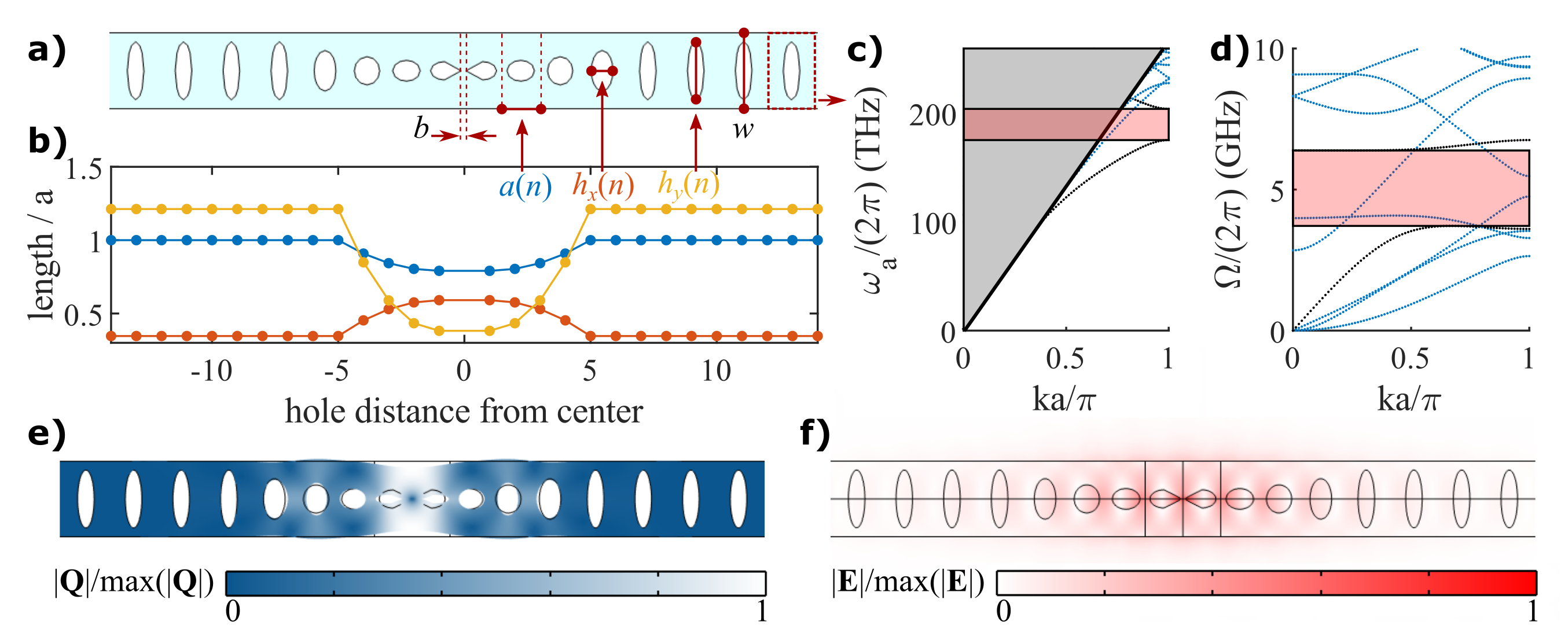
At the core of our proposal is a strain concentrator embedded in a one-dimensional optomechanical crystal (1D OMC) (Fig.1a). The 1D OMC consists of a nanobeam with periodically etched ellipses that are adiabatically morphed into a defect cell. We then modify the central unit cells by tapering to a width using a hyperbolic curve. By COMSOL finite element method (FEM) simulation, we predict an optical mode of frequency THz and (Fig. 1(f)), which lies in the mirror cells’ 28.7 THz optical bandgap from 175.28 THz to 203.98 THz (Fig. 1(b)). We predict an acoustic resonance around GHz (Fig. 1(e)) between the 2.41 GHz acoustic bandgap from 4.96 GHz to 7.37 GHz (Fig. 1(d)). In optomechanical crystals, single photon-to-single phonon coupling between a photonic cavity mode and a mechanical resonant mode arises due to the cavity frequency shift induced by the acoustic displacement profile, normalized to the zero-point fluctuation [25, 26]
| (5) |
Note here that the cavity zero-point fluctuation can be approximated using the resonator’s effective mass as
| (6) |
Here, is the mechanical displacement profile and is the density profile (either or 0).
This consists of two explored effects: the moving boundary effect (shift due to moving vacuum-dielectric boundary conditions resulting from mechanical displacement) and the photoelastic effect (frequency shift due to the sum of strain-induced local refractive index changes in the crystal). The vacuum moving boundary coupling can be written as [5, 25]
| (7) |
The photoelastic coupling can be expressed as [26]
| (8) |
Here, is the cavity electric field profile. Expanding the integrand in the numerator of (8), we can write that as [27]
| (9) | ||||
| (10) |
Here, we note that is a function of the diamond crystallographic orientation relative to the device geometry, which runs along in the -plane. Parametrized by , the rotated is given by [27]
| (11) |
where
| (12) |
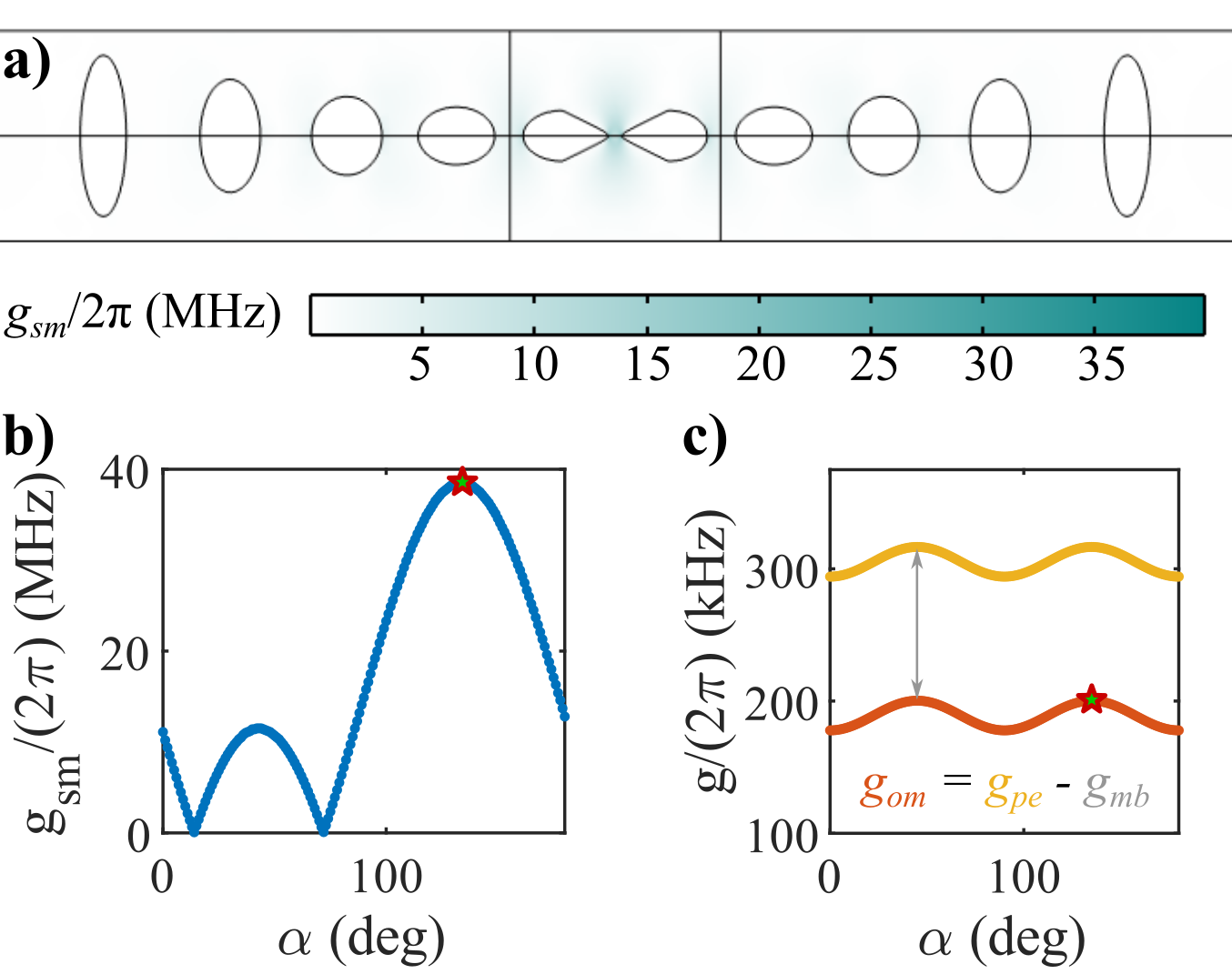
In our simulations, we used [28]. As shown in Fig. 2(c), we find that the anisotropic nature of the photoelastic tensor yields a variation in of about 7% with , maxing out at kHz for rad. Summing with kHz, we find a total vacuum coupling rate kHz.
The ultimate spin-phonon coupling is a function of the strain-induced profile (Fig. 2(a)). We use to indicate the effective spin-orbital coupling resulting from a change in SiV- transition frequency as a function of displacement-induced strain [29],
| (13) |
Here, PHz/strain is the strain-susceptibility parameter describing the mixing of SiV- orbitals, and and describe the strain tensor components of the SiV-. [17, 30, 29]. The SiV- -axis is offset from the diamond axis by polar angle rad and azimuthal angle rad [17]. So, to get and of the SiV- from crystal tensor components, we apply the rotation operation
| (14) |
Note that varies by location in the cavity; as such, we have plotted the location of maximum in our cavity for each mechanical mode in Fig. 2(b). We find that is maximized at an angle rad, with a maximum value MHz, owing to phase matching between and terms (see Appendix B).
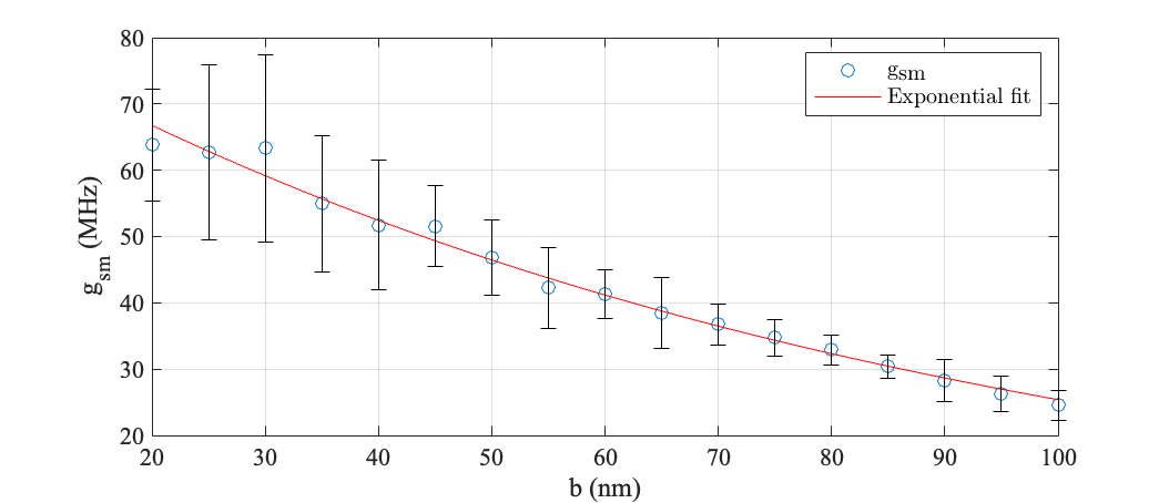
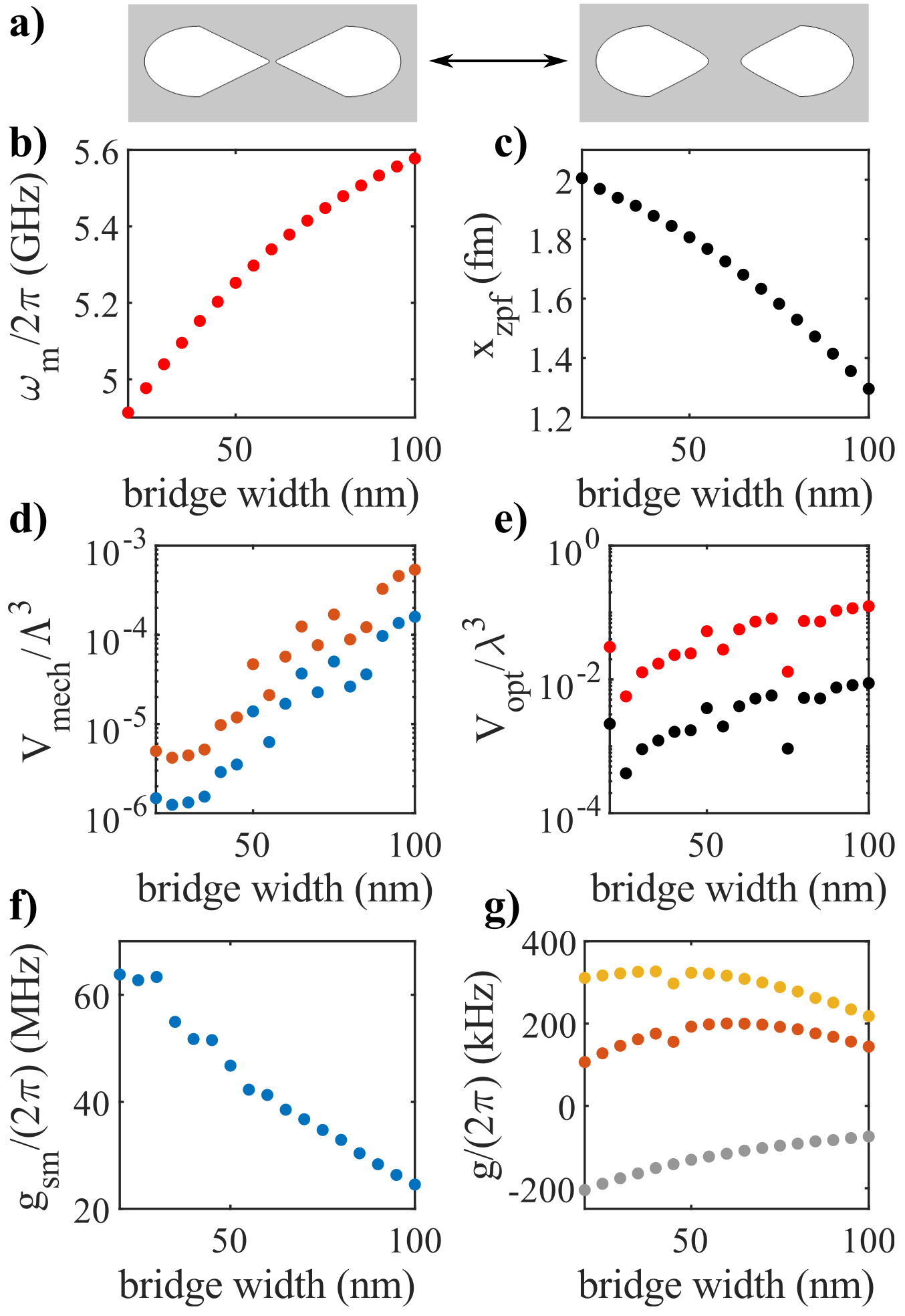
We note here the impact of changing : as is decreased, the optical and acoustic mode profiles become more strongly influenced by the concentrator, whereas for larger the modes are spread across the neighboring defect cells. Mechanically, a smaller (Fig. 3(a) left) can be interpreted as a weakening spring constant in the central bridge between the masses of the walls surrounding the bridge. Hence, as decreases, decreases and increases (Fig. 3(b)-(c)). For a decreasing “spring constant” and increasing , we expect the strain in the central cavity to increase, boosting . Indeed, we observe this effect in simulation (Fig. 3(d)).
Another interpretation of the increase in with decreasing is that of mechanical mode volume [21]: as decreases, the strain energy density of the mechanical mode becomes more highly concentrated in the taper, thereby decreasing the mechanical mode volume dramatically. We estimate through FEM that and drop from and , respectively, to and , respectively, as decreases from 100 nm to 20 nm (Fig. 3d). Here, and are the longitudinal and shear wave velocities in bulk diamond [21]. As decreases, increases, which also increases the “mechanical Purcell enhancement.” or similarly decrease from and , respectively, to and , respectively, with decreasing (Fig. 3e)–a beneficial effect for simultaneously concentrating the cavity mechanical and optical modes. Here, is the free space cavity wavelength, and is the refractive index of diamond.
With decreasing optical mode volume, we expect the cavity optical energy density to be more confined in the concentrator for decreasing [24], which leads to two potentially competing effects. The first is that any photoelastic- or moving boundary-based contributions to within the concentrator will be magnified; but the second is that the effective volume of dielectric over which these magnified effects manifest decreases. We see that, based on these competing effects, a bridge width of nm optimizes for our design (Fig. 3(g)). Making as small as possible optimizes (Fig. 3f), but we assume a lower bound of nm for ease of fabrication. We observe here that placing the emitters as close to the edge of the taper as possible will maximize . This proximity to dielectric walls normally imposes a limitation on the optical coherence of an emitter, but because our scheme interacts with the emitter non-optically, we can circumvent this obstacle.
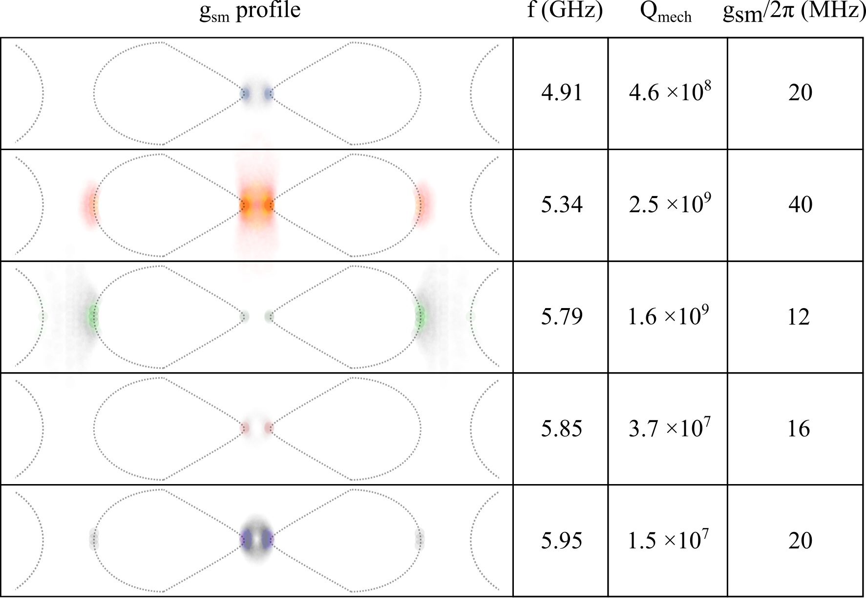
In Fig. 4, we test the idea that the coupling mode of interest is sufficiently spaced from other mechanical modes in frequency. By plotting the profiles of all modes of MHz within 2 GHz of GHz, we find that these “high ” modes are at least MHz apart from the mode of interest and feature at most half as high over the mode profile. Parasitic spin-mechanical coupling to these modes can be modeled as a loss channel of the primary mechanical mode alongside the intrinsic mechanical loss , with loss to mode given by
| (15) |
From the closest mode at GHz, which has a similar profile to the mode of interest, we find that kHz. This corresponds to an effective quality factor . From FEM simulations, we find that mechanical quality factors are higher than this parasitic coupling-induced (see Appendix A), indicating that external resonances will limit the cavity phonon lifetime. However, this is only true when our quantum emitter is implanted precisely in the concentrated coupling region of the parasitic mode, which from Fig. 4 is visually more compact than the mode of interest. If our emitters are implanted at a distance from the dielectric boundary, then these parasitic loss channels become weaker. We also note that, in the event that multiple emitters are implanted in the cavity, one can tune a single emitter into resonance by modifying the external magnetic field to vary the Zeeman splitting of each emitter. This can also allow for addressing multiple emitters individually via the same optomechanical cavity.
Another limiting loss channel is thermal losses, which can be characterized as phonon-phonon interactions using the Akhiezer or Landau-Rumer loss models [31, 32, 33, 34]. At higher temperatures, these losses will dominate due to the greater presence of thermal phonons in the cavity. At lower temperatures, other losses–including clamping losses, parasitic coupling, and material losses–will likely dominate.
III Remote Entangling Protocols
The controlled opto-mechanical two-mode squeezing represented by Eq. 2 enables us to herald the creation of single phonons in the mechanical resonator. Such excitations can then be deterministically transferred to the spin for long term storage. Crucially, if we employ the Duan, Lukin, Cirac, and Zoller’s [35, 36] entangling protocol, we can herald an entangled state in two remote mechanical resonators. Each of the two mechanical resonators can then deterministically swap its content with their embedded spins, leading to two remote entangled long-lived spins for use in quantum networking.
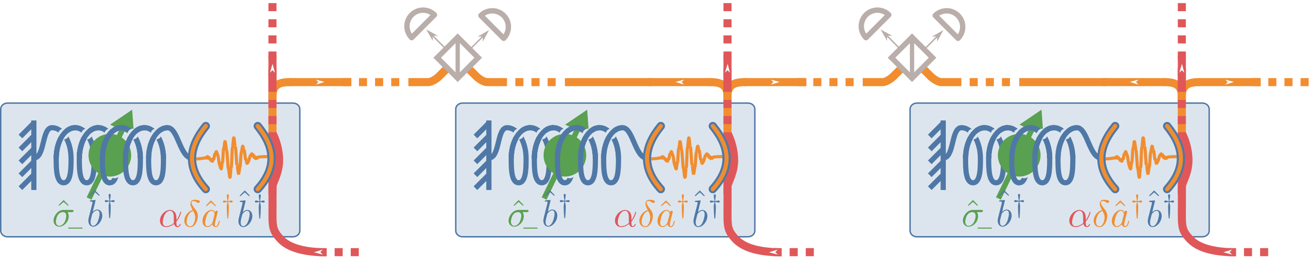
The DLCZ protocol is, at its core, two single-phonon heralding experiments running in parallel as seen in Fig. 5. However, the detector triggering the heralding is placed after a “path erasure apparatus”, e.g. a simple 50-50 beamsplitter. Therefore, when a phonon is heralded by the detection of a photon, the phonon is in equal superposition of being in the left or in the right node. This results in the two mechanical resonators being in the state , with the phase depending on which detector clicked. For a details on this path erasure consult [35, 37].
Below we study the fidelity and success probability of the single-phonon heralding protocol, as its performance directly affects the performance of the overall entanglement protocol. In this process, when writing down kets, we will use the Fock basis of the optical and mechanical modes, written down in that order, e.g., is zero photons and one phonon. Two processes are involved in the single-phonon heralding: the two-mode squeezing in Eq. 2 which leads to the mapping ; and the leakage into a waveguide and subsequent detection of the photon, which projects on the branches. To properly derive the the dynamics we will use a stochastic master equation and we will track the most-probable quantum trajectories manually. The dynamics is governed by the equation
| (16) |
where the the sum over jump operators provides a way to track the chance for discontinuous jumps. If is the state obtained after evolving under , then the probability density for a jump is . The operator represents the chance of photon leakage at rate with the optical quality factor; corresponds to a phonon leaking to the heat bath at rate , where with the quality factor of the mechanical resonator (notice the different convetion leading to a factor of 2 difference); lastly corresponds to receiving a phonon from the bath at rate , where is the average number of phonons in the bath, is the Boltzman constant, and is the temperature of the bath. Solving for the dynamics and the probability densities of various jumps, as done in details in the interactive supplementary materials [38] leads to:
-
1.
To zeroth order, no jump occurs.
-
2.
To first order, a photon-phonon pair is heralded. The probability of that event is .
-
3.
To second order, a photon-phonon pair is heralded and then followed by any other event, for an overall of probability .
-
4.
Also to second order, a event at time is followed by an event, happening with .
-
5.
Similarly for followed by we have probability .
Above, is the duration of the pump pulse. These are all the branches of the dynamics that have a chance of triggering a heralding event (to leading order). The total chance for heralding is , while the fidelity of the heralded single phonon is , where is the fidelity of “good heralding” branch of the dynamics. is the density matrix for the state conditioned on only one event having happened during the pump pulse of duration .
After simplifying and taking into account that the decay of the optical cavity is much faster than the optomechanical interaction (), we obtain:
| (17) |
| (18) |
Notice the term in the infidelity that scales exactly as the heralding probability: This is due to the next-to-leading-order effect in the two-mode squeezing, leading to a proportionally larger chance of more-than-one excitations being heralded. There is also a second term, purely related to the detrimental effects of the thermal bath on the mechanical resonator. As long as we can neglect the bath heating term, however this can be difficult to quantify as strongly depends on . This transition between leading sources of infidelity can be seen in Fig. 6.
These are the heralding probability and fidelity of a single phononic excitation. The heralding probability and fidelity for the complete entangling protocol, in which two nodes are pumped in parallel and the photon is looked for only after “path-information erasure” differ. To leading order, the probability is twice as high as either node can produce a photon, and the infidelity scales the same.
For long term storage, we coherently swap the phononic excitation into the spin. The swap gate contributes an additional infidelity of which is much lower than other sources of infidelity.
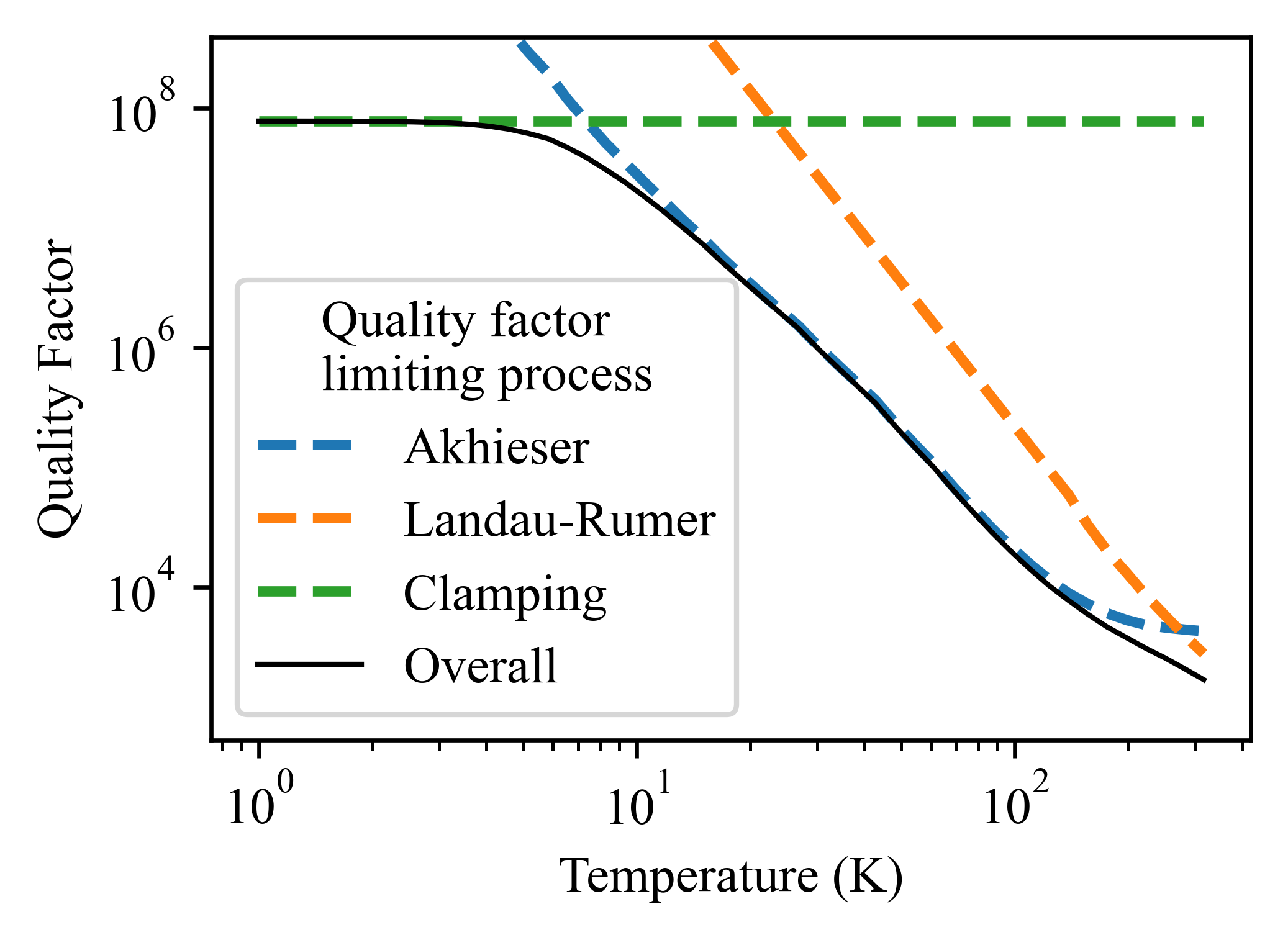
These results, given the design parameters of the previous section, are detailed in Fig. 6. Of note is that is very strongly dependent on the bath temperature due to scattering processes among the thermal phonons. At low temperatures, only clamping losses due to the design of the resonator are of importance, but as the temperature increases, Akhieser and then Landau-Rumer processes become important [39, 40, 41, 42]. The typical dependence for our design and material parameters can be seen in Fig. 7. The Akhieser limited quality factor is , where is density, is speed of light, is the Grüneisen coefficient, and is the thermal conductivity. Only depends strongly on temperature, and we use the values reported in [43, 44, 45, 46, 47, 48]. At even higher temperature the Landau-Rumer processes dominate with , where is the diamond heat capacity as reported in [49, 50].
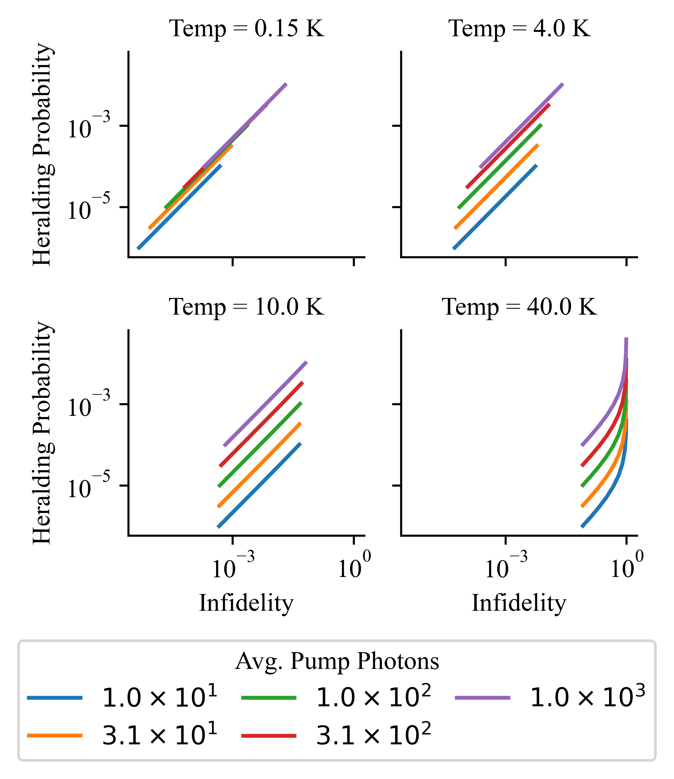
Thus, with our design we can theoretically achieve single-phonon generation at tens of kHz and infidelity lower than at temperature , number of photons in the pump mode , pump pulse duration . At lower temperatures the performance significantly improves, giving limiting infidelities far below .
Possible improvements to the protocol include (1) spectral and spatial multiplexing (2) use of a Dicke state of multiple nearby color centers to enhance (3) use the nuclear registers for even longer storage times (4) entanglement purification with the nuclear registers which greatly increase the entanglement fidelity while only marginally decreasing the entanglement rate.
IV Discussion and Outlook
In this paper, we bring the idea of a self-similar concentrator from photonic crystal devices [24] to a 1D optomechanical crystal and explore the usage of the resulting cavity in spin-optomechanical interfacing. This system poses the advantages afforded by highly concentrated optical and mechanical modes: high strain in a central region while retaining optomechanical coupling in diamond relative to previously proposed and demonstrated devices [22], and thus strong spin-phonon interactions. From FEM simulations, we demonstrate that this spin-optomechanical interface can achieve kHz single photon-phonon coupling alongside MHz spin-phonon coupling to a Group IV spin. The strength of this spin-phonon interaction is such that we can effectively ignore losses incurred when swapping a quantum between a cavity phonon and the spin state.
We explore implementation of our interface in an optically heralded entanglement protocol [35, 37]. In this scheme, identical cavities are entangled via heralding, and the resulting entangled phonons are swapped into their respective coupled spins. This entanglement procedure completely circumvents standard issues related to spin-addressing, including the need to operate at the emitter’s optical transition wavelength (we define the optical wavelength with a telecom photonic mode) and concerns related to spectral diffusion of emitters (we never optically excite the emitter). Additionally, this scheme places no strong requirements on the optical quality factors required by other works to accomplish spin-mechanical addressing [51, 52]–instead operating with low optical s to increase the rate of heralding–and requires on-chip devices that are well within fabricable parameters.
| Defect | Mat. | (@T) | (@T) | |
|---|---|---|---|---|
| SiV- | Dmd | 40MHz | 0.1ms@40mK[53] | 0.2ms@40mK[53] |
| SnV- | Dmd | 3.5MHz | 10ms@3K[54] | 0.3ms@1.7K[55] |
| NV- | Dmd | 30Hz | 100s@20K[56] | 0.6s@77K[57] |
| B:Si | Si | 20MHz | 5ms@25mK[58] | 0.9ms@25mK[58] |
| P:Si | Si | MHz | 0.3s@7K[59] | 60ms@7K[59] |
| V:Si | SiC | Hz | s@17K[60] | ms @17K[60] |
Our spin-optomechanical architecture applies to other material platforms besides diamond. For example, silicon (Si) and silicon carbide (SiC) have been used for optomechanics [5, 7, 63, 64, 65, 66] and have quantum emitters including carbon-based T-centers, phosphorus vacancies, and boron impurities [67, 18]. In particular, Si with B:Si acceptor impurities has been considered for operating spin-phonon coupled systems as an acoustic alternative to circuit-cavity QED [18]. Here, we have shown that with an intentionally designed optomechanical cavity, one can achieve much larger than previously proposed–which should be the case irrespective of the material, whether diamond, silicon, or another alternative–alongside respectable , such that the full spin-optomechanical interface’s performance can be evaluated (see Table 1). We have analyzed this interface assuming a SiV- spin, which has well-documented spin-strain parameters [17, 30]; however this spin is indistinguishable above single-Kelvin temperatures [54]. As such, future works may use this spin-optomechanical framework while selecting a suitable combination of material platform and temperature-robust, highly strain-tunable spin defect. The ability to separately engineer quantum memories and spin-photon interfaces, while retaining efficient interfacing between them even at moderate temperatures up to 40 K, will provide much-needed design freedom in applications from quantum networks to computing to sensing.
Acknowledgements.
The authors would like to thank Matthew Trusheim and Gen Clark for insightful comments on this research. The Julia and Python open source communities provided invaluable research software. The hardware design was done in COMSOL. SK and HR are grateful for the funding provided by the MITRE Quantum Moonshot Program. HR acknowledges support from the NDSEG Fellowship and the NSF Center for Ultracold Atoms. DE acknowledges support from NSF.References
- Kepler [1619] J. Kepler, De cometis libelli tres (Typis Andre Apergeri, sumptibus Sebastiani Mylii, bibliopol Augustani, 1619).
- Aspelmeyer et al. [2014] M. Aspelmeyer, T. J. Kippenberg, and F. Marquardt, Cavity optomechanics: nano-and micromechanical resonators interacting with light (Springer, 2014).
- Ashkin [1978] A. Ashkin, Trapping of atoms by resonance radiation pressure, Physical Review Letters 40, 729 (1978).
- Cuthbertson et al. [1996] B. Cuthbertson, M. Tobar, E. Ivanov, and D. Blair, Parametric back-action effects in a high-q cyrogenic sapphire transducer, Review of Scientific Instruments 67, 2435 (1996).
- Eichenfield et al. [2009a] M. Eichenfield, J. Chan, R. M. Camacho, K. J. Vahala, and O. Painter, Optomechanical crystals, Nature 462, 78 (2009a).
- Eichenfield et al. [2009b] M. Eichenfield, R. Camacho, J. Chan, K. J. Vahala, and O. Painter, A picogram-and nanometre-scale photonic-crystal optomechanical cavity, nature 459, 550 (2009b).
- Chan et al. [2012] J. Chan, A. H. Safavi-Naeini, J. T. Hill, S. Meenehan, and O. Painter, Optimized optomechanical crystal cavity with acoustic radiation shield, Applied Physics Letters 101, 081115 (2012).
- Wilson-Rae et al. [2007] I. Wilson-Rae, N. Nooshi, W. Zwerger, and T. J. Kippenberg, Theory of ground state cooling of a mechanical oscillator using dynamical backaction, Physical Review Letters 99, 093901 (2007).
- Vainsencher et al. [2016] A. Vainsencher, K. Satzinger, G. Peairs, and A. Cleland, Bi-directional conversion between microwave and optical frequencies in a piezoelectric optomechanical device, Applied Physics Letters 109, 033107 (2016).
- Mirhosseini et al. [2020] M. Mirhosseini, A. Sipahigil, M. Kalaee, and O. Painter, Quantum transduction of optical photons from a superconducting qubit, arXiv preprint arXiv:2004.04838 (2020).
- Forsch et al. [2020] M. Forsch, R. Stockill, A. Wallucks, I. Marinković, C. Gärtner, R. A. Norte, F. van Otten, A. Fiore, K. Srinivasan, and S. Gröblacher, Microwave-to-optics conversion using a mechanical oscillator in its quantum ground state, Nature Physics 16, 69 (2020).
- Jiang et al. [2020] W. Jiang, C. J. Sarabalis, Y. D. Dahmani, R. N. Patel, F. M. Mayor, T. P. McKenna, R. Van Laer, and A. H. Safavi-Naeini, Efficient bidirectional piezo-optomechanical transduction between microwave and optical frequency, Nature communications 11, 1 (2020).
- Wu et al. [2020] M. Wu, E. Zeuthen, K. C. Balram, and K. Srinivasan, Microwave-to-optical transduction using a mechanical supermode for coupling piezoelectric and optomechanical resonators, Physical Review Applied 13, 014027 (2020).
- Riedinger et al. [2018] R. Riedinger, A. Wallucks, I. Marinković, C. Löschnauer, M. Aspelmeyer, S. Hong, and S. Gröblacher, Remote quantum entanglement between two micromechanical oscillators, Nature 556, 473 (2018).
- Zhong et al. [2020] C. Zhong, X. Han, H. X. Tang, and L. Jiang, Entanglement of microwave-optical modes in a strongly coupled electro-optomechanical system, Physical Review A 101, 032345 (2020).
- Childress [2007] L. I. Childress, Coherent manipulation of single quantum systems in the solid state (Harvard University, 2007).
- Hepp et al. [2014] C. Hepp, T. Müller, V. Waselowski, J. N. Becker, B. Pingault, H. Sternschulte, D. Steinmüller-Nethl, A. Gali, J. R. Maze, M. Atatüre, et al., Electronic structure of the silicon vacancy color center in diamond, Physical Review Letters 112, 036405 (2014).
- Ruskov and Tahan [2013] R. Ruskov and C. Tahan, On-chip cavity quantum phonodynamics with an acceptor qubit in silicon, Phys. Rev. B 88, 064308 (2013).
- Maity et al. [2020] S. Maity, L. Shao, S. Bogdanović, S. Meesala, Y.-I. Sohn, N. Sinclair, B. Pingault, M. Chalupnik, C. Chia, L. Zheng, et al., Coherent acoustic control of a single silicon vacancy spin in diamond, Nature communications 11, 1 (2020).
- Shandilya et al. [2021] P. K. Shandilya, D. P. Lake, M. J. Mitchell, D. D. Sukachev, and P. E. Barclay, Optomechanical interface between telecom photons and spin quantum memory (2021), arXiv:2102.04597 [quant-ph] .
- Schmidt et al. [2020] M. K. Schmidt, C. G. Poulton, and M. J. Steel, Acoustic diamond resonators with ultrasmall mode volumes, Physical Review Research 2, 033153 (2020).
- Burek et al. [2016] M. J. Burek, J. D. Cohen, S. M. Meenehan, N. El-Sawah, C. Chia, T. Ruelle, S. Meesala, J. Rochman, H. A. Atikian, M. Markham, et al., Diamond optomechanical crystals, Optica 3, 1404 (2016).
- Cady et al. [2019] J. V. Cady, O. Michel, K. W. Lee, R. N. Patel, C. J. Sarabalis, A. H. Safavi-Naeini, and A. C. B. Jayich, Diamond optomechanical crystals with embedded nitrogen-vacancy centers, Quantum Science and Technology 4, 024009 (2019).
- Choi et al. [2017] H. Choi, M. Heuck, and D. Englund, Self-similar nanocavity design with ultrasmall mode volume for single-photon nonlinearities, Phys. Rev. Lett. 118, 223605 (2017).
- Johnson et al. [2002] S. G. Johnson, M. Ibanescu, M. Skorobogatiy, O. Weisberg, J. Joannopoulos, and Y. Fink, Perturbation theory for maxwell’s equations with shifting material boundaries, Physical review E 65, 066611 (2002).
- Safavi-Naeini and Painter [2014] A. H. Safavi-Naeini and O. Painter, Optomechanical crystal devices, in Cavity Optomechanics (Springer, 2014) pp. 195–231.
- Chan et al. [2011] J. Chan, T. M. Alegre, A. H. Safavi-Naeini, J. T. Hill, A. Krause, S. Gröblacher, M. Aspelmeyer, and O. Painter, Laser cooling of a nanomechanical oscillator into its quantum ground state, Nature 478, 89 (2011).
- Lang [2009] A. Lang, The strain-optical constants of diamond: A brief history of measurements, Diamond and related materials 18, 1 (2009).
- Neuman et al. [2020] T. Neuman, M. Eichenfield, M. Trusheim, L. Hackett, P. Narang, and D. Englund, A phononic bus for coherent interfaces between a superconducting quantum processor, spin memory, and photonic quantum networks, arXiv preprint arXiv:2003.08383 (2020).
- Meesala et al. [2018] S. Meesala, Y.-I. Sohn, B. Pingault, L. Shao, H. A. Atikian, J. Holzgrafe, M. Gündoğan, C. Stavrakas, A. Sipahigil, C. Chia, et al., Strain engineering of the silicon-vacancy center in diamond, Physical Review B 97, 205444 (2018).
- Akhiezer [1961] A. Akhiezer, On the absorption of sound in solids, Journal of Physics (Moscow) 1, 277 (1961).
- Landau and Rumer [1937] L. D. Landau and Y. B. Rumer, Absorption of sound in solids, Phys. Z. Sowjetunion 11 (1937).
- Woodruff and Ehrenreich [1961] T. O. Woodruff and H. Ehrenreich, Absorption of sound in insulators, Phys. Rev. 123, 1553 (1961).
- Tabrizian et al. [2009] R. Tabrizian, M. Rais-Zadeh, and F. Ayazi, Effect of phonon interactions on limiting the f.q product of micromechanical resonators, in TRANSDUCERS 2009 - 2009 International Solid-State Sensors, Actuators and Microsystems Conference (2009) pp. 2131–2134.
- Duan et al. [2001] L.-M. Duan, M. D. Lukin, J. I. Cirac, and P. Zoller, Long-distance quantum communication with atomic ensembles and linear optics, Nature 414, 413 (2001).
- Krastanov et al. [2021a] S. Krastanov, H. Raniwala, J. Holzgrafe, K. Jacobs, M. Lončar, M. J. Reagor, and D. R. Englund, Optically heralded entanglement of superconducting systems in quantum networks, Physical Review Letters 127, 040503 (2021a).
- Krastanov et al. [2021b] S. Krastanov, H. Raniwala, J. Holzgrafe, K. Jacobs, M. Lončar, M. J. Reagor, and D. R. Englund, Optically-heralded entanglement of superconducting systems in quantum networks (2021b), arXiv:2012.13408 [quant-ph] .
- Krastanov [2022] S. Krastanov, Optomechanics two-mode squeezing and single phonon heralding (2022).
- Ghaffari et al. [2013] S. Ghaffari, S. A. Chandorkar, S. Wang, E. J. Ng, C. H. Ahn, V. Hong, Y. Yang, and T. W. Kenny, Quantum limit of quality factor in silicon micro and nano mechanical resonators, Scientific reports 3, 1 (2013).
- Duwel et al. [2006] A. Duwel, R. N. Candler, T. W. Kenny, and M. Varghese, Engineering mems resonators with low thermoelastic damping, Journal of microelectromechanical systems 15, 1437 (2006).
- Kunal and Aluru [2011] K. Kunal and N. Aluru, Akhiezer damping in nanostructures, Physical Review B 84, 245450 (2011).
- Maris [1971] H. J. Maris, Interaction of sound waves with thermal phonons in dielectric crystals, in Physical Acoustics, Vol. 8 (Elsevier, 1971) pp. 279–345.
- Technology [2021] D. M. A. D. Technology, The CVD diamond booklet (Diamond Materials: Advanced Diamond Technology, 2021).
- Pohl [1963] R. Pohl, The applicability of the debye model to thermal conductivity, Zeitschrift für Physik 176, 358 (1963).
- Berman et al. [1953] R. Berman, F. E. Simon, and J. M. Ziman, The thermal conductivity of diamond at low temperatures, Proceedings of the Royal Society of London. Series A. Mathematical and Physical Sciences 220, 171 (1953).
- Pan and Kania [1994] L. S. Pan and D. R. Kania, Diamond: Electronic Properties and Applications: Electronic Properties and Applications, Vol. 294 (Springer Science & Business Media, 1994).
- Barman and Srivastava [2007] S. Barman and G. Srivastava, Temperature dependence of the thermal conductivity of different forms of diamond, Journal of Applied Physics 101, 123507 (2007).
- Graebner and Herb [1992] J. Graebner and J. Herb, Dominance of intrinsic phonon scattering, Diamond Films and Technology 1 (1992).
- Reeber and Wang [1996] R. R. Reeber and K. Wang, Thermal expansion, molar volume and specific heat of diamond from 0 to 3000k, Journal of Electronic Materials 25, 63 (1996).
- Corruccini and Gniewek [1960] R. J. Corruccini and J. J. Gniewek, Specific Heats and Enthalpies of Technical Solids at Low Temperatures: A Compilation from the Literature, Vol. 21 (US Government Printing Office, 1960).
- Ji et al. [2020] J.-W. Ji, Y.-F. Wu, S. C. Wein, F. K. Asadi, R. Ghobadi, and C. Simon, Proposal for room-temperature quantum repeaters with nitrogen-vacancy centers and optomechanics, arXiv preprint arXiv:2012.06687 (2020).
- Ghobadi et al. [2019] R. Ghobadi, S. Wein, H. Kaviani, P. Barclay, and C. Simon, Progress toward cryogen-free spin-photon interfaces based on nitrogen-vacancy centers and optomechanics, Physical Review A 99, 053825 (2019).
- Becker et al. [2018] J. N. Becker, B. Pingault, D. Groß, M. Gündoğan, N. Kukharchyk, M. Markham, A. Edmonds, M. Atatüre, P. Bushev, and C. Becher, All-optical control of the silicon-vacancy spin in diamond at millikelvin temperatures, Phys. Rev. Lett. 120, 053603 (2018).
- Trusheim et al. [2020] M. E. Trusheim, B. Pingault, N. H. Wan, M. Gündoğan, L. De Santis, R. Debroux, D. Gangloff, C. Purser, K. C. Chen, M. Walsh, J. J. Rose, J. N. Becker, B. Lienhard, E. Bersin, I. Paradeisanos, G. Wang, D. Lyzwa, A. R.-P. Montblanch, G. Malladi, H. Bakhru, A. C. Ferrari, I. A. Walmsley, M. Atatüre, and D. Englund, Transform-limited photons from a coherent tin-vacancy spin in diamond, Phys. Rev. Lett. 124, 023602 (2020).
- Debroux et al. [2021] R. Debroux, C. P. Michaels, C. M. Purser, N. Wan, M. E. Trusheim, J. Arjona Martínez, R. A. Parker, A. M. Stramma, K. C. Chen, L. de Santis, E. M. Alexeev, A. C. Ferrari, D. Englund, D. A. Gangloff, and M. Atatüre, Quantum control of the tin-vacancy spin qubit in diamond, Phys. Rev. X 11, 041041 (2021).
- Jarmola et al. [2012] A. Jarmola, V. M. Acosta, K. Jensen, S. Chemerisov, and D. Budker, Temperature- and magnetic-field-dependent longitudinal spin relaxation in nitrogen-vacancy ensembles in diamond, Phys. Rev. Lett. 108, 197601 (2012).
- Bar-Gill et al. [2013] N. Bar-Gill, L. M. Pham, A. Jarmola, D. Budker, and R. L. Walsworth, Solid-state electronic spin coherence time approaching one second, Nature communications 4, 1 (2013).
- Kobayashi et al. [2021] T. Kobayashi, J. Salfi, C. Chua, J. van der Heijden, M. G. House, D. Culcer, W. D. Hutchison, B. C. Johnson, J. C. McCallum, H. Riemann, et al., Engineering long spin coherence times of spin–orbit qubits in silicon, Nature Materials 20, 38 (2021).
- Tyryshkin et al. [2003] A. M. Tyryshkin, S. A. Lyon, A. V. Astashkin, and A. M. Raitsimring, Electron spin relaxation times of phosphorus donors in silicon, Phys. Rev. B 68, 193207 (2003).
- Simin et al. [2017] D. Simin, H. Kraus, A. Sperlich, T. Ohshima, G. V. Astakhov, and V. Dyakonov, Locking of electron spin coherence above 20 ms in natural silicon carbide, Phys. Rev. B 95, 161201 (2017).
- Whiteley et al. [2019] S. J. Whiteley, G. Wolfowicz, C. P. Anderson, A. Bourassa, H. Ma, M. Ye, G. Koolstra, K. J. Satzinger, M. V. Holt, F. J. Heremans, et al., Spin–phonon interactions in silicon carbide addressed by gaussian acoustics, Nature Physics 15, 490 (2019).
- Soykal et al. [2011] O. O. Soykal, R. Ruskov, and C. Tahan, Sound-based analogue of cavity quantum electrodynamics in silicon, Phys. Rev. Lett. 107, 235502 (2011).
- Ren et al. [2020] H. Ren, M. H. Matheny, G. S. MacCabe, J. Luo, H. Pfeifer, M. Mirhosseini, and O. Painter, Two-dimensional optomechanical crystal cavity with high quantum cooperativity, Nature communications 11, 1 (2020).
- Lu et al. [2015] X. Lu, J. Y. Lee, and Q. Lin, High-frequency and high-quality silicon carbide optomechanical microresonators, Scientific reports 5, 1 (2015).
- Lu et al. [2019] X. Lu, J. Y. Lee, S. D. Rogers, and Q. Lin, Silicon carbide double-microdisk resonator, Optics letters 44, 4295 (2019).
- Lu et al. [2020] X. Lu, J. Y. Lee, and Q. Lin, Silicon carbide zipper photonic crystal optomechanical cavities, Applied physics letters 116, 221104 (2020).
- Bergeron et al. [2020] L. Bergeron, C. Chartrand, A. T. K. Kurkjian, K. J. Morse, H. Riemann, N. V. Abrosimov, P. Becker, H.-J. Pohl, M. L. W. Thewalt, and S. Simmons, Silicon-integrated telecommunications photon-spin interface, PRX Quantum 1, 020301 (2020).
Appendix A Simulations of Optomechanical Crystal
The diamond optomechanical crystal was designed and simulated using the finite element method (FEM) in COMSOL Multiphysics 5.4. Simulations began with the analysis of a nanobeam unit cell (LABEL:fig:TO_DO). Mechanically, we simulate the eigenmodes of the unit cell with Floquet boundary condition defined by
| (19) |
where is the mechanical displacement profile at a given and . Similarly, the simulate the electromagnetic eigenmodes using the Floquet boundary equation
| (20) |
where is the electric field at a given . Bandstructures for these simulations are shown in Fig. 1c-d in the main text. After locating optical and mechanical bandgaps, the unit cells were varied by changing unit cell parameters to their “defect unit cell” values of to re-simulate mechanical and optical bandstructures at the point (for the mechanical breathing mode) and the X point (for the electromagnetic confined mode). Finally, the central two unit cells were modified to add the concentrating taper. A rectangular section of length and height was subtracted from the center of the crystal, connecting the two central ellipses. Next, the central taper was filled according to the intersection of the rectangular top and bottom lines with two hyperbolic curves following the (right hand side) equation (mirrored on the left-hand side)
| (21) |
This resulted in the geometry shown in Fig. 1a. The completed nanostructure was then simulated using the Solid Mechanics and Electromagnetic Waves, Frequency Domain (ewfd) physics modules and Eigenmode solver in COMSOL. The introduction of a central taper necessitated further modifying of the defect unit cell parameters, so were varied slightly to induce optical and acoustic modes that were near the center of the optical and acoustic band gaps, respectively, of the mirror unit cells.
The mechanical (clamping) and optical s (Fig. LABEL:) were calculated as a function of central bridge width for the high--and- breathing mode (Fig. 1).
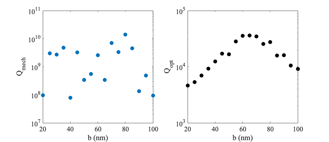
From these simulations, we find that will likely not limit the overall mechanical quality factor. can likely be tuned for each according to radiation cancellation [24], but for our heralded entanglement protocol, primarily dictates the detection rate of a photon-phonon pair generation event. This leakage rate should be greater than the rate of phonon decay (i.e. ) to ensure the acoustic phonon is not lost by the time the accompanying photon is detected. Hence, it is not important (nor necessarily favorable) for us to optimize in this paper.
Appendix B Calculation of Spin-Phonon Coupling
Spin-phonon coupling was calculated using FEM simulations in COMSOL. The Euler angle representing the in-plane rotation of the diamond crystal orientation relative to the -axis of the nanobeam was swept as . For the subsequent calculations of , we assume that the diamond crystal -axis is oriented along the high-symmetry axis of the defect , along , and along , such that the SiV- experiences [29]
| (22) |
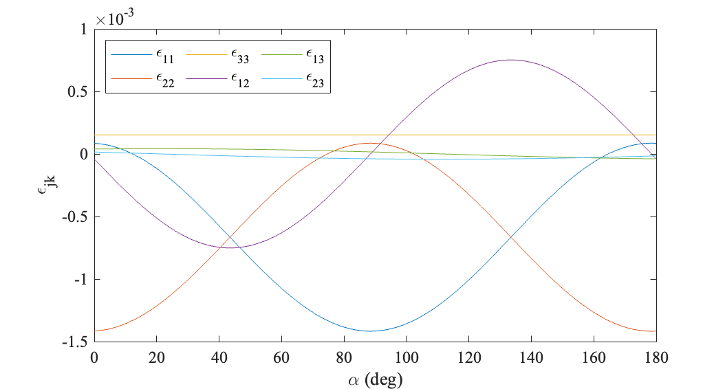
The for each was calculated by taking the coupling at the middle of the right-edge of the central taper at ten slices from to . This was done to reduce numerical noise in the FEM simulation that resulted from extremely small elements experiencing dramatic deformation without increasing the mesh density to untenable levels.