Zero-Reference Image Restoration for Under-Display Camera of UAV
Abstract
The exposed cameras of UAV can shake, shift, or even malfunction under the influence of harsh weather, while the add-on devices (Dupont lines) are very vulnerable to damage. We can place a low-cost T-OLED overlay around the camera to protect it, but this would also introduce image degradation issues. In particular, the temperature variations in the atmosphere can create mist that adsorbs to the T-OLED, which can cause secondary disasters (i.e., more severe image degradation) during the UAV’s filming process. To solve the image degradation problem caused by overlaying T-OLEDs, in this paper we propose a new method to enhance the visual experience by enhancing the texture and color of images. Specifically, our method trains a lightweight network to estimate a low-rank affine grid on the input image, and then utilizes the grid to enhance the input image at block granularity. The advantages of our method are that no reference image is required and the loss function is developed from visual experience. In addition, our model can perform high-quality recovery of images of arbitrary resolution in real time. In the end, the limitations of our model and the collected datasets (including the daytime and nighttime scenes) are discussed.
 |
1 Introduction
 |
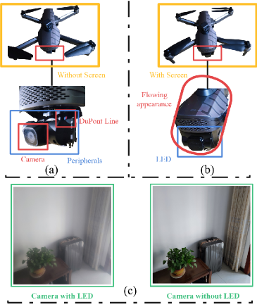
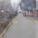
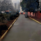
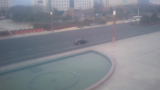
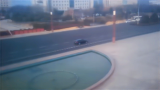
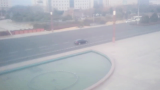
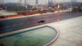
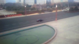
In extreme environments, the exposed cameras of UAVs are susceptible to wind and meteorological factors that can lead to camera failure. To solve this issue, we design a low-cost scheme to keep the stability of the camera system of the exposed camera on the UAV, as shown in Figure 1 (b). Specifically, we use a low-cost Transparent OLED (T-OLED) to wrap around the camera device. All-in-one design can provide better user perceptive (see Figure 1 (b), for instance the flowing appearance) and other intelligent experience Zhou et al. (2021). More importantly, this design offers a reference for saving the complicated peripherals around the camera, thereby reducing the weight of the UAV. However, this new system is mired in the same morass as the Under-Display Camera (UDC) Zhou et al. (2021); Sundar et al. (2020); Kwon et al. (2021); Feng et al. (2021); Yuqian Zhou, David Ren, Kyle Tolentino, et al. (2020); Yang and Sankaranarayanan (2021), because it is relatively difficult to retain full functionality of an imaging sensor after mounting it behind a display. Specifically, the imaging quality of a camera will be degraded due to lower light transmission rate and diffraction effects Zhou et al. (2021). Moreover, the image quality degradation is further exacerbated because the temperature difference between the land and the sky creates a haze that adheres to the protector. As a result, the captured image clings to the surface of the image as if there is a white veil (the camera with T-OLED in Figure 1 (c)).
Currently, image restoration methods focused on UDC are trained on a pair of the blurred and clear images Zhou et al. (2021); Sundar et al. (2020). Unfortunately, it is difficult for us to obtain a pair of the blurred and the clear images due to the instability of the UAV at high altitude. In this study, we endeavor to implement the image restoration task without reference images by leveraging the UDC prior rather than considering the high-cost GAN techniques Jiang et al. (2021); Afifi et al. (2021). In simple terms, our approach does not require any paired information in the training process.
To achieve our goal, we propose a novel lightweight deep learning-based method, Zero-Reference Under-Display Camera Network (ZRUDC-Net), for UDC image enhancement on the UAV. It can cope with a variety of luminance conditions, including uniform chromatic aberration and water haze disturbance. Instead of performing image-to-image mapping, we reformulate the task as an image-specific affine estimation problem. In detail, we estimate an affine transformation tensor (the channel is ) acting on the raw input image by using a smoothing slicing operator. For the affine transformation tensor (affine grid), we can learn it end-to-end through the U-Net Ronneberger et al. (2015). Second, we develop a zero-reference learning pattern thanks to sophisticated technologies Cai et al. (2020a); Golts et al. (2020); Guo et al. (2020). This is achieved through a set of specially designed non-reference loss functions, including spatial consistency loss, exposure control loss, color constancy loss, dark and bright channel priors loss, and light smoothing loss. At last, we discuss in the work the limitations and struggles imposed by collecting data sets, especially for nighttime scenes.
In summary, the main contributions of our work are: (1) We empirically develop a pipeline based on the visual experience and use this pipeline to guide us in formulating the final solution, including the design of the network and the configuration of the loss functions. (2) We propose the first zero-reference UDC enhancement network that is independent of paired and unpaired training information. Numerous experiments have demonstrated the effectiveness of our method. (3) We collect the first UDC dataset on the UAV (diverse visual scenes are included) which will be released and evaluated by the public.
2 Related Work
UDC imaging and restoration.
Several previous work proposed positioning the camera under the display panel to obtain high-resolution photos Cheng et al. (2019); Zhou et al. (2021); Emerton et al. (2020). T-OLED is a better display panel Cheng et al. (2019) and is commonly used in commercial televisions, cellphones and mobile devices. Recently, several works Kwon et al. (2016); Qin et al. (2016, 2017) described and analyzed the diffraction effects of UDC systems. However, these works cannot tackle the image restoration problem. Although several works Hirsch et al. (2009); Suh et al. (2013, 2012) proposed camera-behind-display design, these are low-resolution images with very low-quality content and are not suitable for everyday photography. Zhou et al. Zhou et al. (2021) and the ECCV challenge Yuqian Zhou, David Ren, Kyle Tolentino, et al. (2020) attempted to address the problem of UDC image restoration with publicly released datasets. However, the above methods have an obvious drawback that the non-clear images carry only one form of image degradation. Some approaches Zhang (2020); Sethumadhavan et al. (2020) attempted to develop deep CNNs to handle the low SNR and large blur in under-panel imagery. We also refer to the architecture of these methods to generate the required affine coefficients for the raw images.
Unsupervised single image restoration.
Currently numerous unsupervised techniques are employed for image enhancement tasks such as GAN-based approaches Afifi et al. (2021); Jiang et al. (2021). Although GAN-based methods can yield outstanding results in image restoration, such methods require paired or unpaired images as an auxiliary, which is costly. Fortunately, Zero-Net Guo et al. (2020) provides an efficient and sophisticated idea to tackle the problem of image degradation. Therefore, we can refer this approach to solve the image degradation problem by combining dark and bright channel priors Golts et al. (2020); Cai et al. (2020b).
3 Motivation and Methodology
Our task is a blind image degradation problem, and the point spread function (PSF) is hard to estimate from the degraded image. Because the photography conditions of the UAV in the air are enormously complex, with not only blur but also saturation overflow and other problems, we can only solve these ill-posed problems from visual experience. Based on the intuitive visual experience and analysis, we design a new pipeline (see Figure 3 (a) (c)) that attempts to address the problem of image degradation on the UAV. Finally, on the basis of this pipeline, we design a zero-reference image enhancement strategy.
3.1 Motivation
| (a) Real-world input image | (b) DCP + Gamma | (c) Zero-Net |
The conventional UDC problem (the image degradation) is usually addressed by an end-to-end network trained on a pair of blurred and clear images Kwon et al. (2021); Zhou et al. (2021). Unfortunately, since UAVs move video at high altitude, it is not easy to collect high-quality paired training data. So far, we consider to enhance the degraded images based on our visual intuition. As shown in Figure 3 (a), real-world images from the UAV with T-OLED can generate many cases of image degradation (overexposure, dark corners and blur, etc.). To solve these ill-posed problems, we propose a pipeline (Figure 3 ()) to enhance the images.
The pipeline.
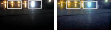
We first need to solve the problem marked in green box in Figure 3 (a). Based on visual experience, this is a case where the image is hazed. DCP He et al. (2009) is the most classical technique to solve the image with haze but it also leads to a series of problems, such as the whole image is lightless. To mitigate this problem, Gamma correction is available as a general technique to relieve images from darkness. We performed a combination of DCP and Gamma correction for Figure 3 (a) and the results are shown in Figure 3 (b). Although the haze-like phenomenon is resolved, it still leaves a massive spoil behind (see the artifacts and the dark corner parts in Figure 3 (b)). So we consider using a low-light image enhancement approach (Zero-Net) to further solve this problem, as shown in Figure 3 (c). The reason for considering the utilization of Zero-Net is that it is an unsupervised method, which provides us with technical support to solve the degradation problem of reference-free images. Obviously, the overall image brightness is improved, but there is still some noise in local patches.
So far, we still have three unresolved challenges, one is sky artifacts, another is local blurring of the image, and the last is local overexposure. Based on this empirical pipeline, we attempt to further enhance the visual performance by using the following solutions. 1) The dark channel prior loss Golts et al. (2020) is utilized to replace the DCP and Gamma correction strategy as it alleviates the problem of sky artifacts. 2) The loss functions provided by Zero-Net Guo et al. (2020) are used, and notably we have empirically adjusted the exposure loss function. 3) The brightness and the dark channel prior Cai et al. (2020b) are also applied to modify the local blurring and over-exposure, and several such regular terms are enforced in this work.
Based on the above solutions, we design a zero-reference UDC-Net to run a degraded image of arbitrary (including ultra high definition images) resolution in real time.
3.2 ZRUDC-Net
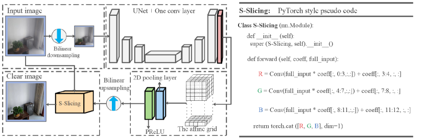
Given an arbitrary resolution input, our network first reconstructs the affine grid using a modified U-Net Ronneberger et al. (2015) on a fixed resolution of the input. Capitalizing on the regressed affine grid, we can generate high-quality affine coefficients. Moreover, to obtain the low-rank affine grid, we use pooling layers to limit its space characteristics. Figure 2 illustrates the architecture of the proposed single zero-reference UDC restoration approach, which consists of four parts: downsampling of the input image, generating an affine grid, obtaining the low-rank affine grid and producing a clear image.
Affine grid learning.
It is well-known that bilateral learning Gharbi et al. (2017) in image restoration tasks is a well-reliable technique. Its core lies the estimation of a bilateral grid to regress a high quality affine coefficient tensor (the channels are 12). However, this depends heavily on the extraction of the guidance information, which is performed on a full-resolution image, and therefore only several convolution kernels can be used to estimate it (to reach the goal of real-time processing). To further boost the modelling speed, we use the deep network directly to learn an affine grid.
First, we reduce the raw input image to a fixed resolution of and extract low-level features by a U-Net and a convolution layer as shown in Figure 2. This yields a array of the feature maps that contains rich textures and edges (see Figure 4 (b)). also can be viewed as a information grid, where each grid cell contains 12 numbers, one for each coefficient of a affine transformation matrix. Then we use the 2D pooling layer and a PReLU layer acting on to obtain a smaller scale . Specifically, a multi-channel affine grid whose third dimension has been unrolled:
| (1) |
where denotes the coordinates of the affine grid cell, and each cell has number. In addition, denotes the affine grid is downsampled in both height and width dimensions. is regarded as an array of low rank for the full-resolution affine grid of the next stage. That is because the procedure from to is implemented through the use of the linear operator (interpolation). To demonstrate the effectiveness of the 2D pooling layer and the PReLU layer in the proposed network, we also performed an ablation study which is discussed in the subsequent section.
 |
Smoothing Slicing.
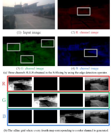
Capitalizing on the predicted affine grid coefficient , we need to transfer this information back to the full-resolution content of the raw input to produce a high-quality clean image. We introduce the S-Slicing operation on the three channels of color as shown Figure 4, and we give the PyTorch-style pseudo-code on the right of Figure 2 for the details of the scheme. Note that the bilateral learning uses an additive operator to squeeze the channels, while we use a learned convolution operator. As shown in Figure 4 (a), we visualize the by-products of the affine grids after the affine transformation of the original image, and we can see that the textures of all three of them complement each other and play a characteristic resembling that of bilateral learning. This workflow maintains effectiveness while reducing inference time significantly.
 |
 |
 |
 |
 |
 |
 |
 |
 |
 |
 |
 |
| (a) Input | (b) DCP + Zero-Net | (c) HDRNet | (d) DAGF | (e) DEUNet | (f) ZRUDC-Net |
| CVPR’09 + CVPR’20 | TOG’17 | ECCV’20 | CVPR’21 | Ours |
| (a) Input | (b) DCP + Zero-Net | (c) HDRNet | (d) DAGF | (e) DEUNet | (f) ZRUDC-Net |
| CVPR’09 + CVPR’20 | TOG’17 | ECCV’20 | CVPR’21 | Ours |
3.3 Non-Reference Loss Functions
We propose a basket of differentiable non-reference losses to enable zero-reference learning on deep network. The following six types of losses are enforced to train the ZRUDC-Net.
Dark channel prior loss.
The dark channel prior is an image statistical property, indicating that the darkest pixels in all color channels are very dark and close to zero in a small block of a haze-free outdoor image. Golts et al. Golts et al. (2020) found an idea from the soft matting approach to design a loss function based on the dark channel prior. Mccartney and Hall Mccartney and Hall (1977) designed a cyclic system on the optical model to avoid overfitting while dehazing, which is an unsupervised strategy. The dark channel prior loss is a remarkably significant loss term for our algorithm, but it also depends much on the initialized configuration.
Spatial consistency loss.
We use a spatial consistency loss to enhance image through preserving the difference of neighboring regions (left, right, down and top) between patches of the input image. The enhanced formula is shown as follows:
| (2) |
where is the number of local patches, is neighboring regions centered at the region . and denote the average intensity values of each local region in the model output and the input image, respectively. The loss term empirically sets the size of the local region to in this study.
Exposure control loss.
To address over-exposed regions, especially for the sky and the night lights, we use an exposure control loss to keep the exposure degree. The loss can be expressed as:
| (3) |
where represents the number of non-overlapping local regions of size , is the average intensity value of a local region in the enhanced image. represents the distance between the average intensity value of any local regions.
Color constancy loss.
We use a color constancy loss to correct the color deviations in the enhanced image and reconstruct the relations among the three adjusted channels. This loss can be expressed as:
| (4) |
where denotes the average intensity value of channel in the enhanced image, represents a pair of channels.
Illumination smoothness loss.
We use the illumination smoothness loss function to preserve the linear relations between neighboring pixels, which is defined as:
| (5) |
where represents the number of iteration, and represent the horizontal and the vertical gradient operations, respectively. The four loss functions as described above are denoted by the term for convenience in the next description, and the weight coefficients of each term we adopt the native version Guo et al. (2020).
Dark and bright channels loss.
Enforcing a regularization term on the features of the bright and the dark channels is beneficial to restoring a sharp image, especially, for a sparse regularization term Cai et al. (2020b). In this work, we use an -regularization term to enforce sparsity on both dark and bright channels of shallow features. The dark and bright channels loss is defined as :
| (6) |
where and are the conventional methods to extract the information of the dark channel and the bright channel, respectively.
The total loss can be expressed as :
| (7) |
where , and are the weights of the losses. In this work, we set the , and to , and , respectively.
 |
 |
 |
 |
 |
| (a) Input | (b) Ours | (c) w/o | (d) w/o | (e) w/o |
4 Experiments
In the section, we evaluate the proposed approach by conducting experiments on both a public dataset Yuqian Zhou, David Ren, Kyle Tolentino, et al. (2020) and our collected real-world images (including records in extreme weather such as rainy). All the results are compared against four image restoration methods: DCP + Zero-Net He et al. (2009); Guo et al. (2020), HDRNet Gharbi et al. (2017), DAGF Sundar et al. (2020), DEUNet Zhou et al. (2021). In addition, we conduct ablation studies to demonstrate the effectiveness of each module of our network.
Implementation details.
To train and test the proposed network as well as the comparison methods, we develop a new high resolution image restoration dataset on UAV with T-OLED, which consists of 30,000 frames blur images from 15 video clips by UAVs. Since clean labels are missing, we can test the pre-trained model of the above method directly on this dataset.
The proposed model is implemented in PyTorch and Adam optimizer is used to train the model. We use the full-resolution images with a batch size 21 to train the network. The initial learning rate is set to 0.002. We train the network 100 epochs in total. For DCP + Zero-Net method, we conduct different window sizes to trade-off the accuracy and the efficiency, and is finally applied in the experiment. In addition, to assess the situation in the extreme weather, we fine-tuned deep learning based models on the raindrop dataset Qian et al. (2018). The fine-tuning methods all use a learning rate of 0.01, the SGD method, and a batchsize of 8.
Qualitative and Quantitative Evaluation.
The comparison experiments are evaluated on two datasets: Ours and the T-OLED dataset Zhou et al. (2021). Our model is fine tuned on the training data of the T-OLED dataset. Sample results on four images (including two images of rainy weather) from our dataset and four images from the T-OLED dataset, as shown in Figure 5 and Figure 6. DCP + Zero-Net and HDRNet tend to over-enhance the results (over-exposure), while other models still cannot handle the real-world images (remain some haze in the results). However, the restoration images generated by our method in Figure 5- 6 (f) trade-offs the exposure and a pleasing visual perception is obtained. The quantitative results on the T-OLED dataset reported in Table 1 demonstrate the effectiveness of our proposal.
| PSNR | SSIM | LPIPS | Time | |
|---|---|---|---|---|
| DCP + Zero-Net | 21.22 | 0.6990 | 0.4289 | 538ms |
| HDRNet | 29.81 | 0.8197 | 0.2779 | 20ms |
| DAGF | 35.89 | 0.9707 | 0.1255 | 48ms |
| DEUNet | 36.71 | 0.9713 | 0.1209 | 25ms |
| Ours | 37.77 | 0.9689 | 0.1189 | 18ms |
Ablation Study.
To demonstrate the effectiveness of each loss function and the 2D pool layer in ZRUDC-Net, we perform an ablation study involving the following two experiments:
1) w/o , w/o , and w/o : We remove these loss functions respectively on training our proposed dataset.
2) Kernel size of the 2D pool layer: we use different kernel sizes of the 2D pool layer in our network to train the T-OLED dataset.
| K=None | K=3 | K=8 | K=16 | |
|---|---|---|---|---|
| PSNR | 37.59 | 37.77 | 36.13 | 30.86 |
| SSIM | 0.9701 | 0.9689 | 0.9554 | 0.9020 |
5 Limitations and Discussion
In this study, we have two limitations: 1) we do not consider the UAV camera situation under P-LED, and 2) as shown in the Figure 8, we have bad image recovery at night, especially for the illumination information.
 |
For our proposed deep network, we provide a more direct and efficient strategy to generate arbitrary resolution of the enhanced image (see Figure 5) compared to bilateral learning methods. In addition, for HDRNet Gharbi et al. (2017), we replace the additive operator with a convolutional operator in the slicing process, and the PSNR value is increased on the FIVEK dataset. More discussions are described in the supplementary materials.
6 Conclusion
In this paper, we propose a zero-reference image restoration method via ZRUDC-Net and visual experiences. The key to our method is using different loss functions to build regression task, which effectively maintains the detailed edges and enhances the color of the image. At the same time, we establish ZRUDC-Net to handle images of arbitrary resolution (including ultra high definition image) in real time. Quantitative and qualitative results show that our proposed method can generate visually-pleasing results on the non-clear images.
References
- Afifi et al. [2021] Mahmoud Afifi, Marcus A. Brubaker, and Michael S. Brown. HistoGAN: Controlling colors of GAN-generated and real images via color histograms. In CVPR, 2021.
- Cai et al. [2020a] Jianrui Cai, Wangmeng Zuo, and Lei Zhang. Dark and bright channel prior embedded network for dynamic scene deblurring. TIP, 29:6885–6897, 2020.
- Cai et al. [2020b] Jianrui Cai, Wangmeng Zuo, and Lei Zhang. Dark and bright channel prior embedded network for dynamic scene deblurring. TIP, 29:6885–6897, 2020.
- Cheng et al. [2019] Chi Jui Cheng, Tzu Chin Huang, Wen Tsan Lin, Cheng Chih Hsieh, Peng Yu Chen, Peter Lu, and Hoang Yan Lin. Evaluation of diffraction induced background image quality degradation through transparent OLED display. In SID Symposium Digest of Technical Papers, 2019.
- Emerton et al. [2020] Neil Emerton, David Ren, and Tim Large. Image capture through TFT arrays. In SID Symposium Digest of Technical Papers, 2020.
- Feng et al. [2021] Ruicheng Feng, Chongyi Li, Huaijin Chen, Shuai Li, Chen Change Loy, and Jinwei Gu. Removing diffraction image artifacts in under-display camera via dynamic skip connection network. In CVPR, pages 662–671, 2021.
- Gharbi et al. [2017] Michaël Gharbi, Jiawen Chen, Jonathan T. Barron, Samuel W. Hasinoff, and Frédo Durand. Deep bilateral learning for real-time image enhancement. TOG, 36(4):118:1–118:12, 2017.
- Golts et al. [2020] Alona Golts, Daniel Freedman, and Michael Elad. Unsupervised single image dehazing using dark channel prior loss. TIP, 29:2692–2701, 2020.
- Guo et al. [2020] Chunle Guo, Chongyi Li, Jichang Guo, Chen Change Loy, Junhui Hou, Sam Kwong, and Runmin Cong. Zero-reference deep curve estimation for low-light image enhancement. In CVPR, 2020.
- He et al. [2009] Kaiming He, Jian Sun, and Xiaoou Tang. Single image haze removal using dark channel prior. In CVPR, 2009.
- Hirsch et al. [2009] Matthew Hirsch, Douglas Lanman, Henry Holtzman, and Ramesh Raskar. BiDi screen: a thin, depth-sensing LCD for 3D interaction using light fields. TOG, 28(5):1–9, 2009.
- Jiang et al. [2021] Yifan Jiang, Xinyu Gong, Ding Liu, Yu Cheng, Chen Fang, Xiaohui Shen, and Jianchao Yang. EnlightenGAN: Deep light enhancement without paired supervision. TIP, 30:2340–2349, 2021.
- Kwon et al. [2016] Hyeok-Jun Kwon, Chang-Mo Yang, Min-Cheol Kim, Choon-Woo Kim, Ji-Young Ahn, and Pu-Reum Kim. Modeling of luminance transition curve of transparent plastics on transparent OLED displays. Electronic Imaging, 2016(20):1–4, 2016.
- Kwon et al. [2021] Kinam Kwon, Eunhee Kang, Sangwon Lee, and Su-Jin Lee. Controllable image restoration for under-display camera in smartphones. In CVPR, 2021.
- Mccartney and Hall [1977] E. J. Mccartney and F. F. Hall. Optics of the atmosphere: Scattering by molecules and particles. Phys. Today, 1977.
- Qian et al. [2018] Rui Qian, Robby T. Tan, Wenhan Yang, Jiajun Su, and Jiaying Liu. Attentive generative adversarial network for raindrop removal from a single image. In CVPR, pages 2482–2491, 2018.
- Qin et al. [2016] Zong Qin, Yu-Hsiang Tsai, Yen-Wei Yeh, Yi-Pai Huang, and Han-Ping David Shieh. See-through image blurring of transparent organic light-emitting diodes display: calculation method based on diffraction and analysis of pixel structures. Journal of Display Technology, 12(11):1242–1249, 2016.
- Qin et al. [2017] Zong Qin, Jing Xie, Fang-Cheng Lin, Yi-Pai Huang, and Han-Ping D Shieh. Evaluation of a transparent display’s pixel structure regarding subjective quality of diffracted see-through images. IEEE Photonics Journal, 9(4):1–14, 2017.
- Ronneberger et al. [2015] Olaf Ronneberger, Philipp Fischer, and Thomas Brox. U-Net: Convolutional networks for biomedical image segmentation. In MICCAI, 2015.
- Sethumadhavan et al. [2020] Hrishikesh Panikkasseril Sethumadhavan, Densen Puthussery, Melvin Kuriakose, and Jiji Charangatt Victor. Transform domain pyramidal dilated convolution networks for restoration of under display camera images. In ECCV, 2020.
- Suh et al. [2012] Sungjoo Suh, Changkyu Choi, Kwonju Yi, Dusik Park, and Changyeong Kim. An LCD display system with depth-sensing capability based on coded aperture imaging. In SID Symposium Digest of Technical Papers, 2012.
- Suh et al. [2013] Sungjoo Suh, Changkyu Choi, Dusik Park, and Changyeong Kim. Adding depth-sensing capability to an OLED display system based on coded aperture imaging. In SID Symposium Digest of Technical Papers, 2013.
- Sundar et al. [2020] Varun Sundar, Sumanth Hegde, Divya Kothandaraman, and Kaushik Mitra. Deep atrous guided filter for image restoration in under display cameras. In ECCV Workshops, 2020.
- Yang and Sankaranarayanan [2021] Anqi Yang and Aswin C. Sankaranarayanan. Designing display pixel layouts for under-panel cameras. TPAMI, 43(7):2245–2256, 2021.
- Yuqian Zhou, David Ren, Kyle Tolentino, et al. [2020] Yuqian Zhou, David Ren, Kyle Tolentino, et al. UDC 2020 challenge on image restoration of under-display camera: Methods and results. In ECCV Workshops, 2020.
- Zhang [2020] Zhenhua Zhang. Image deblurring of camera under display by deep learning. In SID Symposium Digest of Technical Papers, 2020.
- Zhou et al. [2021] Yuqian Zhou, David Ren, Neil Emerton, Sehoon Lim, and Timothy A. Large. Image restoration for under-display camera. In CVPR, 2021.