Optomechanical crystal with bound states in the continuum
Abstract
Chipscale micro- and nano-optomechanical systems, hinging on the intangible radiation-pressure force, have shown their unique strength in sensing, signal transduction, and exploration of quantum physics with mechanical resonators. Optomechanical crystals, as one of the leading device platforms, enable simultaneous molding of the band structure of optical photons and microwave phonons with strong optomechanical coupling. Here, we demonstrate a new breed of optomechanical crystals in two-dimensional slab-on-substrate structures empowered by mechanical bound states in the continuum (BICs) at 8 GHz. We show symmetry-induced BIC emergence with optomechanical couplings up to MHz per unit cell, on par with low-dimensional optomechanical crystals. Our work paves the way towards exploration of photon-phonon interaction beyond suspended microcavities, which might lead to new applications of optomechanics from phonon sensing to quantum transduction.
Cavity-optomechanics has attracted extensive studies in recent years because of the rich physics associated with the nonlinear optomechanical interaction and a broad range of prospective applications from signal transduction to sensing aspelmeyer2014cavity . One of the leading optomechanical device architectures is optomechanical crystals eichenfield2009optomechanical , where micro- and nano-scale structures give rise to strong radiation-pressure force coupling between wavelength-similar optical photons and microwave phonons. By band-structure engineering of suspended optomechanical crystals, both one-dimensional and quasi-two-dimensional defect cavities eichenfield2009optomechanical ; safavi2014two ; ren2020two have been created with long-lived optical and mechanical resonances maccabe2020nano . Such optomechanical crystal microcavities have enabled groundbreaking quantum experiments including ground-state cooling of mechanical resonators chan2011laser , testing Bell inequality marinkovic2018optomechanical , and a mechanical quantum memory wallucks2020quantum .
Despite the success of optomechanical microcavities, it is highly desirable to explore two-dimensional optomechanical crystals. On one hand, two-dimensional optomechanical crystals offer more degrees of freedom for manipulation of photon-phonon interaction to induce collective phenomena ludwig2013quantum ; brendel2017pseudomagnetic ; brendel2018snowflake ; ren2020topological . On the other hand, extended optomechanical crystals, especially in unsuspended structures sarabalis2017release ; qi2021nonsuspended ; zhang2021silicon , might alleviate the optical-absorption induced heating that plagues released microcavities meenehan2014silicon . Ideally, such slab-on-substrate optomechanical crystals should facilitate dissipation of heat phonons while sustaining long-lived mechanical resonances in the device layer.
Recently, mechanical bound states in the continuum (BICs) are observed in two-dimensional slab-on-substrate phononic crystals tong2020observation . Despite having a zero Bloch wavevector and thus spectrally immersing in the sound cone of the substrate, these mechanical BICs are confined in the slab because of the symmetry-induced decoupling from the acoustic radiation field. There are also proposals and demonstrations of mechanical BICs in microcavities due to, for example, accidental radiation amplitude cancellation chen2016mechanical ; yu2021observation . A significant step forward thus would be coupling mechanical BICs with optical resonances in an optomechanical crystal which will bring the effective radiation-pressure force control and associated functionalities.
In this work, we realize two-dimensional silicon-on-insulator optomechanical crystals with mechanical BICs coupled with optical guided resonances. In such periodic optomechanical crystals, the radiation-pressure coupling between the mechanical BIC and optical modes strongly depends on the mode symmetry zhao2019mechanical , which in many cases dictates an adversely null optomechanical coupling. Here, taking into account of both symmetry of the optomechanical crystal and the silicon crystal lattice, we are able to achieve optomechanical coupling up to MHz per unit cell between a mechanical BIC at 8 GHz and an optical band-edge mode at 193 THz, which is comparable to one-dimensional suspended optomechanical crystals chan2012optimized . With optically-transduced mechanical spectroscopy at room temperature, we demonstrate control of mechanical BICs and optomechanical coupling via the interplay of symmetry of the optomechanical crystal and crystalline material. Our work paves the way for study of photon-phonon interaction in BIC optomechanical crystals at low temperatures, when the benefit of slab-on-substrate device architecture is expected to arise, and Floquet topological physics beyond the tight-binding model fang2019anomalous .
Results
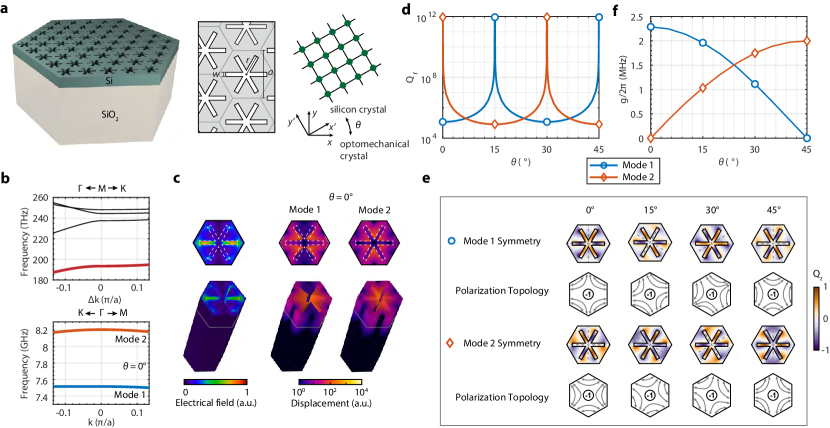
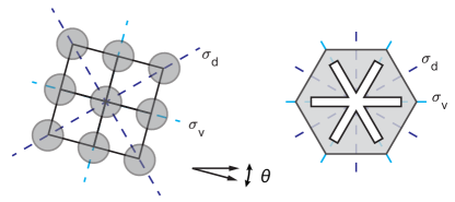
Design of BIC optomechanical crystals. The designed optomechanical crystal in silicon-on-oxide material system has a hexagonal “snowflake” unit cell (Fig. 1a). The reason behind this design is that six-fold symmetric structures tend to yield mechanical BICs coupled with optical guided resonances zhao2019mechanical and, also, the spike feature of the “snowflake” could lead to sizable vibrations for large optomechanical couplings. We consider optical modes at the point below the light cone and mechanical modes at the point. The latter is necessary because mechanical vibrations generally induce a linear perturbation of the optical mode energy, i.e., , and this integral is nonzero in a periodic structure only when the mechanical displacement has a zero Bloch wavevector (Supplementary Information (SI)). Since the refractive index of crystalline silicon is isotropic, the symmetry of optical modes at the point is governed by the group. We select the fundamental transverse-electric(TE)-like mode which is odd with respect to the plane. The stiffness tensor of silicon, on the other hand, is anisotropic in the crystal plane with a group symmetry, which is incommensurable with the group symmetry of the hexagonal optomechanical crystal. As a result, the symmetry of mechanical modes at the point will depend on the orientation angle between the optomechanical crystal and the silicon crystal lattice. When , , , and , the symmetry group of the mechanical mode is , while for other orientations it will be . Only group supports mechanical BICs which decouple from both transverse and longitudinal radiation waves tong2020observation , whose displacement field is perpendicular and parallel to the wavevector, respectively.
Fig. 1b shows the optical band structure near the point and mechanical band structure near the point for and nm, where and are the thickness of the silicon and oxide layers, respectively, is the lattice constant, and are “snowflake” dimensions. The fundamental TE-like optical mode has a frequency of 193 THz and the relevant mechanical modes have frequencies about 7.5 and 8.2 GHz, respectively. Their mode profiles are shown in Fig. 1c. Simulation shows that the radiation quality factor , i.e., the ratio between the frequency and radiation loss rate, of mechanical mode 2 (8.2 GHz) diverges and that of mode 1 is finite but remains relatively high compared to other lossy modes. As a result, for , mode 2 and 1 are mechanical BIC and quasi-BIC, respectively. The fact that mode 1 is a quasi-BIC is because the two mechanical bands are degenerate at the point when the stiffness tensor is isotropic and both modes are BICs belong to the representation of the group; the actual anisotropic stiffness tensor of silicon splits the degeneracy, reducing the representation to (BIC) and (quasi-BIC) representations of the group. Mode 1 turns out to have the representation, leading to coupling with the longitudinal radiation wave. When changes, BIC and quasi-BIC alternate between mode 1 and 2 (while the frequencies of the two modes remain almost unchanged) as shown in Fig. 1d. This is further illustrated in Fig. 1e using the mode symmetry. Below, the mode symmetry under certain symmetry operation is defined with regard to the vector parity of the electric field of the optical mode or the displacement field of the mechanical mode. Taking as an example again, both mode 1 and 2 are even under the 180 rotation, which leads to decoupling from the transverse radiation wave. In addition, mode 2(1) is odd(even) with respect to the symmetry axes (dashed lines), resulting decoupling(coupling) from/with the longitudinal radiation wave and thus a rigorous(quasi) BIC. Same arguments apply to the other three ’s while noticing the mirror symmetry axes rotate with . The mechanical BIC and quasi-BIC are also associated with transverse topological charges, defined as the winding number of far-field transverse polarization around the point tong2020observation . The polarization fields rotate together with , which is unique for the anisotropic mechanical system. For orientations other than the four specific angles, the two modes belong to the representation of the group and thus are quasi-BICs which only couple to the longitudinal acoustic waves. As a result, their quality factor over is significantly higher than unconfined modes.
The interaction between the optical and mechanical modes can be analyzed using the mode symmetry (SI). Roughly, because the -point optical mode energy density is even with respect to the plane, mechanical modes that are odd with respect to the plane, including the BIC for and , will not interact with the optical mode. For other cases, the optomechanical coupling could be nonzero (see Table 1 for a summary), thanks to the incommensurable symmetry of the optomechanical crystal and silicon lattice crystal. The bare optomechanical coupling of a unit cell, , including both moving boundary and photoelastic effects, is calculated and plotted in Fig. 1f. For example, the BIC at has MHz, with a contribution from the moving-boundary and photoelastic effect of MHz and MHz, respectively. The coupling of the “snowflake” optomechanical crystal will increase with smaller air gaps. Here, with a practical air gap nm, the BIC optomechanical crystal achieves a coupling rate (per unit cell) on par with one-dimensional suspended optomechanical crystals chan2012optimized .
| Mode 1 | , quasi-BIC | , BIC | , quasi-BIC | , BIC |
|---|---|---|---|---|
| 0 | ||||
| Mode 2 | , BIC | , quasi-BIC | , BIC | , quasi-BIC |
| 0 |
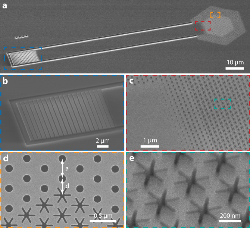
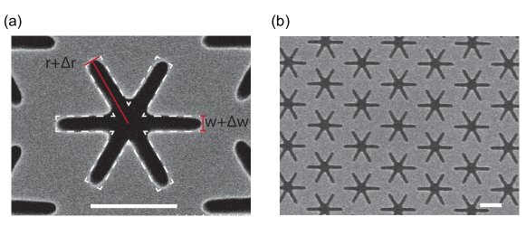
Photonic crystal band-edge multimodes. The optomechanical crystal device is fabricated from a silicon-on-insulator wafer with a 220 nm thick silicon device layer and a 3 µm buried oxide. The air gap of the “snowflake” as small as 30 nm is achieved. The device consists of several functional components (Fig. 2). The hexagonal BIC optomechanical crystal has unit cells along each edge and is surrounded by photonic crystal mirrors with a triangular lattice of cylindrical holes on five edges. The photonic crystal mirror, with the same lattice constant as the snowflake optomechanical crystal, is designed to have a complete TE-like bandgap with the center wavelength around 1550 nm to suppress the lateral radiation of the optical band-edge mode. The photonic crystal mirror is also slightly displaced to minimize the out-of-plane radiation due to the boundary effect on the finite-size optical mode (Fig. 2d). One side of the hexagonal snowflake crystal is connected to a waveguide terminated with an apodized grating coupler for coupling light from a single-mode optical fiber. This configuration makes the optomechanical crystal effectively a one-port device with (mode-dependent) external, i.e., to-waveguide, and intrinsic loss rate of and , respectively. The former can be controlled by the number of photonic crystal mirror layers between the waveguide and optomechanical crystal (Fig. 2c) to achieve different coupling conditions including the critical coupling, i.e., , which is desirable for sideband-resolved mechanical spectroscopy.
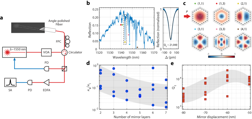
The device is measured using the setup shown in Fig. 3a. An angle-polished optical fiber is used to guide light via the on-chip apodized grating coupler snyder2013packaging ; li2014silicon to the optomechanical crystal and collect the reflected light. The angle of the fiber () and the apodized grating coupler are co-designed to realize an optimized coupling efficiency of for 1550 nm light and 3-dB bandwidth of nm (SI). Because of the reflection at the boundary of finite-size photonic/phononic crystals, band-edge standing-wave resonances will be formed hood2016atom ; jin2019topologically ; tong2020observation ; chua2014larger ; chen2022analytical . The mode envelope of the standing-wave resonances can be approximated by the th order eigenfunctions of a flat-top potential well within the boundary of the photonic/phononic crystal xu2005confined . Fig. 3b shows the optical reflection spectrum of a hexagonal optomechanical crystal with , where a series of band-edge standing-wave resonances are observed. The major order of a standing-wave resonance is identified from the group of resonances it belongs to and the minor order is determined by the position of the resonance in a group. Because of the hyperbolic paraboloid topology of the band structure near the point, resonances with smaller and larger will have shorter wavelengths. In addition, only -odd resonances are observed because the excited waveguide mode is even with respect to the center of the waveguide. Order modes are expected to have deepest resonance dip given they have largest close to the critical coupling. The mode envelop of some standing-wave resonances are shown in Fig. 3c.
The number of photonic crystal mirror layers at the waveguide-optomechanical crystal junction is varied to tune , which is extracted by fitting the optical resonance spectrum using the normalized reflection coefficient of the one-port waveguide-coupled resonator, . Fig. 3d shows of the standing-wave resonance of a group of devices, where a decreasing trend over the number of junction mirror layers is observed as a result of the reduced coupling between the waveguide mode and standing-wave resonances. The displacement of the photonic crystal mirror around the optomechanical crystal is also varied to optimize the total quality factor of the standing-wave resonance. As shown in Fig. 3e, a displacement of nm from the nominal lattice constant is optimal, which is consistent with the simulation (SI). We note the variation of photonic crystal mirrors not only changes but also via the perturbation of the evanescent field, leading to fluctuations of . An optimized optical resonance is shown in Fig. 3b with a total quality factor of while being close to the critical coupling. The quality factor of the optical resonance and its variation is largely due to the disorder induced scattering to the modes above the light cone jin2019topologically .
Room-temperature mechanical spectroscopy. We performed the mechanical spectroscopy at room temperature using a blue-detuned laser with a frequency , where and are the frequencies of the optical and mechanical band-edge modes, respectively. We stabilized the laser-cavity-detuning by locking the device-reflected power with feedback control of the laser frequency (Fig. 3a). For each device, an optical standing-wave resonance with about and close to 1 is chosen, which means the device is operated near the sideband-resolved regime, i.e., . The reflected pump light with sidebands due to the modulation of mechanical modes is sent to a high-speed photodetector. The beating between the pump and sidebands thus yields the mechanical spectrum which is observed by a spectrum analyzer.
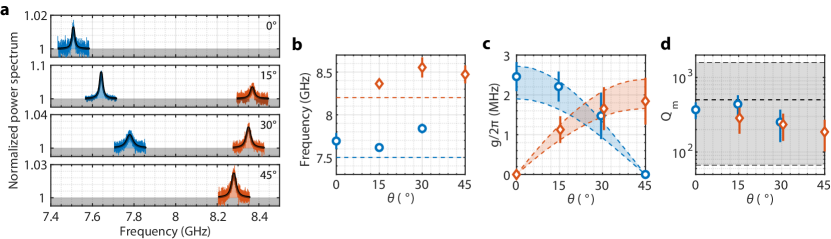
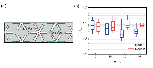
Devices with different orientations between the optomechanical crystal and the silicon crystal lattice are fabricated to reveal the mechanical (quasi-)BICs and the impact of symmetry on the optomechanical interaction. Fig. 4a shows the mechanical spectroscopy of a group of devices with , , , and . The spectrum is normalized with respect to the total background noise. At and , only the quasi-BIC mode is observed while the BIC mode is invisible because of the symmetry-inhibited optomechanical coupling. At and , both BIC and quasi-BIC modes are detected. These observed mechanical modes are the (1,1) standing-wave resonance, while higher order resonances are obscure because of both lower quality factor and optomechanical coupling. Fig. 4b shows the frequency distribution of a group of devices. The occurrence of the mechanical BIC and quasi-BIC modes and their frequencies are consistent with the simulation.
Under a blue-detuned pump, the optomechanical interaction between the mechanical and optical resonances is described by a linearized two-mode squeezing Hamiltonian, , where () and () are the creation and annihilation operators of the optical(mechanical) resonance. The parametrically-enhanced optomechanical mode coupling of standing-wave resonances is given by
| (1) |
where is the average number of photons in one unit cell and is a resonance-dependent parameter due to finite-mode-size correction (SI). Given the nature of weak radiation-pressure force, the important coupling in generic optomechanical systems is the parametric mode coupling, which is related to the cooperativity given by . It is seen from Eq. 1 that the parametric mode coupling of a finite optomechanical crystal is primarily determined by the unit-cell coupling and the per-unit-cell photon number, and is independent of the size of the crystal. In other words, despite that the bare mode coupling of optomechanical crystals roughly scales as , it can be compensated by the large number of photons available which scales with . The per-unit-cell photon number is largely constrained by the thermo-optic effect and the heat capacity of the unit cell, which the slab-on-substrate structure can ameliorate, especially when the thermal conductivity of the substrate is comparable to the slab. In our experiments, the device is typically operated under a pump power of a few mW and is on the order of . The unit-cell optomechanical coupling is extracted from the noise power spectrum (see Methods and SI) and plotted in Fig. 4c. Large optomechanical coupling MHz is observed for the mechanical BIC. The deviation from the simulated value could be due to the variation of the actual snowflake gap size and disorders in the optomechanical crystal. Despite being unreleased and two-dimensional, the optomechanical interaction (per unit cell) in the BIC optomechanical crystal is on par with the suspended low-dimensional optomechanical crystal devices, such as nanobeams.
The quality factor of the observed mechanical modes is shown in Fig. 4d. There are two main factors limiting the mechanical quality factor of the current device. First, the size of the optomechanical crystal is , corresponding to a finite wavevector of for the fundamental standing-wave resonance. The radiation quality factor of mechanical standing-wave resonances with finite wavevectors decreases drastically as they deviate from the BIC at the point tong2020observation . Second, the fabricated optomechanical crystal has critical dimensions as small as 30 nm, which cause random variations among unit cells. These disorders induce scattering between different orders of band-edge resonances, which effectively introduces more radiation channels to a given resonance and degrades its quality factor regan2016direct ; ni2017analytical ; jin2019topologically . The lateral radiation for this size of crystal is not a dominant loss according to the simulation and can be optimized with a phononic crystal mirror. In addition, at room temperature, the quality factor of GHz-frequency mechanical modes is ultimately limited by material absorption to around 1000-2000 eichenfield2009optomechanical . Because of these, there is no significant statistical difference of the quality factor of BIC and quasi-BIC modes. The observed quality factor is verified with numerical simulations of finite super-cells with realistic disorders (SI). However, the mechanical radiation quality factor will increase with the size of optomechanical crystals tong2020observation , which will be critical to low-temperature measurements when the material absorption is suppressed.
Discussion
In summary, we have realized the first two-dimensional slab-on-substrate optomechanical crystals with mechanical BICs. Guided by a symmetry-based design approach, this architecture offers optomechanical interaction (per unit cell) on par with suspended optomechanical crystal devices. The two-dimensional optomechanical crystal with tunable symmetry provides an arena for exploration of rich multimode physics nielsen2017multimode ; renninger2018bulk . In addition, the cavity-less optomechanical crystal might realize Floquet topological physics beyond the tight-binding model fang2019anomalous . The benefit of the slab-on-substrate device architecture in terms of heat dissipation is obscured at room temperature, especially for optomechanical crystals with a large area-to-perimeter ratio, because of the low thermal conductivity of the oxide substrate two orders smaller than silicon. However, such benefit will become evident at low temperatures ( K), relevant for quantum experiments involving GHz mechanical modes, or in a different material systems, when/where the thermal conductivity of the substrate and slab becomes comparable zeller1971thermal ; thompson1961thermal . Besides the suppressed material-absorption loss at low temperatures, the mechanical quality factor could be enhanced using the merging BIC mechanism jin2019topologically and implementing appropriate phononic crystal mirrors. As a consequence, slab-on-substrate BIC optomechanical crystals with improved optical and mechanical losses could be unique at low temperatures for exploration of modalities including phonon sensing and macroscopic mechanical oscillators in the quantum regime chu2017quantum ; kotler2021direct .
Methods
Device fabrication. Devices are fabricated in silicon-on-insulator microchips (220 nm silicon device layer and 3 m buried oxide layer) using electron beam lithography with ZEP520A mask, followed by inductively coupled plasma reactive ion etch of silicon using \chemfigSF_6 and \chemfigCHF_3.
Mechanical noise power spectrum. The total noise power spectral density measured by the photodetector is given by safavi2013laser ; meenehan2014silicon
| (2) |
where is the electronic noise of the detector, is the noise of EDFA, is the optical shot noise, is the mechanical noise spectrum, is the total loss rate of the optical resonance, is the parametrically-enhanced optomechanical coupling, is the total detection efficiency, is the EDFA gain, is the detector gain factor from optical power to voltage, and is the input impedance of the spectrum analyzer. The optically-transduced mechanical noise spectrum is given by
| (3) |
with the thermal occupation of the mechanical mode. The total detection efficiency is , where is the coupling efficiency of the grating coupler at the pump wavelength, is the total transmission efficiency in the optical fiber path from the chip to the detector, and is the quantum efficiency of the photodetector. We measured and depending on the pump wavelength, while is given by the photodetector, which results in . is determined by blocking the light and is determined by removing EDFA while keeping the optical power incident onto the photodetector the same. Then the measured noise power spectrum is fitted using Eqs. 2 and 3, with , , and the only fitting parameters. The unit-cell optomechanical coupling is calculated from , using and depending on the optical standing-wave resonance that is used for the mechanical spectroscopy (SI).
Acknowledgements
This work is supported by US National Science Foundation (Grant No. 1944728 and 2016136) and Office of Naval Research (Grant No. N00014-21-1-2136).
References
- (1) Aspelmeyer, M., Kippenberg, T. J. & Marquardt, F. Cavity optomechanics. Reviews of Modern Physics 86, 1391 (2014).
- (2) Eichenfield, M., Chan, J., Camacho, R. M., Vahala, K. J. & Painter, O. Optomechanical crystals. Nature 462, 78–82 (2009).
- (3) Safavi-Naeini, A. H., Hill, J. T., Meenehan, S., Chan, J., Gröblacher, S. & Painter, O. Two-dimensional phononic-photonic band gap optomechanical crystal cavity. Physical Review Letters 112, 153603 (2014).
- (4) Ren, H., Matheny, M. H., MacCabe, G. S., Luo, J., Pfeifer, H., Mirhosseini, M. & Painter, O. Two-dimensional optomechanical crystal cavity with high quantum cooperativity. Nature Communications 11, 1–10 (2020).
- (5) MacCabe, G. S., Ren, H., Luo, J., Cohen, J. D., Zhou, H., Sipahigil, A., Mirhosseini, M. & Painter, O. Nano-acoustic resonator with ultralong phonon lifetime. Science 370, 840–843 (2020).
- (6) Chan, J., Alegre, T. M., Safavi-Naeini, A. H., Hill, J. T., Krause, A., Gröblacher, S., Aspelmeyer, M. & Painter, O. Laser cooling of a nanomechanical oscillator into its quantum ground state. Nature 478, 89–92 (2011).
- (7) Marinković, I., Wallucks, A., Riedinger, R., Hong, S., Aspelmeyer, M. & Gröblacher, S. Optomechanical bell test. Physical Review Letters 121, 220404 (2018).
- (8) Wallucks, A., Marinković, I., Hensen, B., Stockill, R. & Gröblacher, S. A quantum memory at telecom wavelengths. Nature Physics 16, 772–777 (2020).
- (9) Ludwig, M. & Marquardt, F. Quantum many-body dynamics in optomechanical arrays. Physical Review Letters 111, 073603 (2013).
- (10) Brendel, C., Peano, V., Painter, O. J. & Marquardt, F. Pseudomagnetic fields for sound at the nanoscale. Proceedings of the National Academy of Sciences 114, E3390–E3395 (2017).
- (11) Brendel, C., Peano, V., Painter, O. & Marquardt, F. Snowflake phononic topological insulator at the nanoscale. Physical Review B 97, 020102 (2018).
- (12) Ren, H., Shah, T., Pfeifer, H., Brendel, C., Peano, V., Marquardt, F. & Painter, O. Topological phonon transport in an optomechanical system. arXiv preprint arXiv:2009.06174 (2020).
- (13) Sarabalis, C. J., Dahmani, Y. D., Patel, R. N., Hill, J. T. & Safavi-Naeini, A. H. Release-free silicon-on-insulator cavity optomechanics. Optica 4, 1147–1150 (2017).
- (14) Qi, R., Xu, Q., Wu, N., Cui, K., Zhang, W. & Huang, Y. Nonsuspended optomechanical crystal cavities using as 2 s 3 chalcogenide glass. Photonics Research 9, 893–898 (2021).
- (15) Zhang, J., Roux, X. L., Montesinos-Ballester, M., Ortiz, O., Marris-Morini, D., Vivien, L., Lanzillotti-Kimura, N. D. & Alonso-Ramos, C. Silicon-on-insulator optomechanical microresonator with tight photon and phonon confinement. arXiv preprint arXiv:2103.08465 (2021).
- (16) Meenehan, S. M., Cohen, J. D., Gröblacher, S., Hill, J. T., Safavi-Naeini, A. H., Aspelmeyer, M. & Painter, O. Silicon optomechanical crystal resonator at millikelvin temperatures. Physical Review A 90, 011803 (2014).
- (17) Tong, H., Liu, S., Zhao, M. & Fang, K. Observation of phonon trapping in the continuum with topological charges. Nature Communications 11, 1–7 (2020).
- (18) Chen, Y., Shen, Z., Xiong, X., Dong, C.-H., Zou, C.-L. & Guo, G.-C. Mechanical bound state in the continuum for optomechanical microresonators. New Journal of Physics 18, 063031 (2016).
- (19) Yu, Y., Xi, X. & Sun, X. Observation of bound states in the continuum in a micromechanical resonator. arXiv preprint arXiv:2109.09498 (2021).
- (20) Zhao, M. & Fang, K. Mechanical bound states in the continuum for macroscopic optomechanics. Optics Express 27, 10138–10151 (2019).
- (21) Chan, J., Safavi-Naeini, A. H., Hill, J. T., Meenehan, S. & Painter, O. Optimized optomechanical crystal cavity with acoustic radiation shield. Applied Physics Letters 101, 081115 (2012).
- (22) Fang, K. & Wang, Y. Anomalous quantum hall effect of light in bloch-wave modulated photonic crystals. Physical review letters 122, 233904 (2019).
- (23) Snyder, B. & O’Brien, P. Packaging process for grating-coupled silicon photonic waveguides using angle-polished fibers. IEEE Transactions on Components, Packaging and Manufacturing Technology 3, 954–959 (2013).
- (24) Li, C., Chee, K. S., Tao, J., Zhang, H., Yu, M. & Lo, G. Silicon photonics packaging with lateral fiber coupling to apodized grating coupler embedded circuit. Optics Express 22, 24235–24240 (2014).
- (25) Hood, J. D., Goban, A., Asenjo-Garcia, A., Lu, M., Yu, S.-P., Chang, D. E. & Kimble, H. Atom–atom interactions around the band edge of a photonic crystal waveguide. Proceedings of the National Academy of Sciences 113, 10507–10512 (2016).
- (26) Jin, J., Yin, X., Ni, L., Soljačić, M., Zhen, B. & Peng, C. Topologically enabled ultrahigh-Q guided resonances robust to out-of-plane scattering. Nature 574, 501–504 (2019).
- (27) Chua, S.-L., Lu, L., Bravo-Abad, J., Joannopoulos, J. D. & Soljačić, M. Larger-area single-mode photonic crystal surface-emitting lasers enabled by an accidental dirac point. Optics Letters 39, 2072–2075 (2014).
- (28) Chen, Z., Yin, X., Li, P., Zheng, Z., Zhang, Z., Wang, F. & Peng, C. Analytical theory of finite-size photonic crystal slabs near the band edge. Optics Express 30, 14033–14047 (2022).
- (29) Xu, T., Yang, S., Nair, S. V. & Ruda, H. Confined modes in finite-size photonic crystals. Physical Review B 72, 045126 (2005).
- (30) Regan, E. C., Igarashi, Y., Zhen, B., Kaminer, I., Hsu, C. W., Shen, Y., Joannopoulos, J. D. & Soljačić, M. Direct imaging of isofrequency contours in photonic structures. Science Advances 2, e1601591 (2016).
- (31) Ni, L., Jin, J., Peng, C. & Li, Z. Analytical and statistical investigation on structural fluctuations induced radiation in photonic crystal slabs. Optics Express 25, 5580–5593 (2017).
- (32) Nielsen, W. H. P., Tsaturyan, Y., Møller, C. B., Polzik, E. S. & Schliesser, A. Multimode optomechanical system in the quantum regime. Proceedings of the National Academy of Sciences 114, 62–66 (2017).
- (33) Renninger, W., Kharel, P., Behunin, R. & Rakich, P. Bulk crystalline optomechanics. Nature Physics 14, 601–607 (2018).
- (34) Zeller, R. & Pohl, R. Thermal conductivity and specific heat of noncrystalline solids. Physical Review B 4, 2029 (1971).
- (35) Thompson, J. & Younglove, B. Thermal conductivity of silicon at low temperatures. Journal of Physics and Chemistry of Solids 20, 146–149 (1961).
- (36) Chu, Y., Kharel, P., Renninger, W. H., Burkhart, L. D., Frunzio, L., Rakich, P. T. & Schoelkopf, R. J. Quantum acoustics with superconducting qubits. Science 358, 199–202 (2017).
- (37) Kotler, S., Peterson, G. A., Shojaee, E., Lecocq, F., Cicak, K., Kwiatkowski, A., Geller, S., Glancy, S., Knill, E., Simmonds, R. W. et al. Direct observation of deterministic macroscopic entanglement. Science 372, 622–625 (2021).
- (38) Safavi-Naeini, A. H., Chan, J., Hill, J. T., Gröblacher, S., Miao, H., Chen, Y., Aspelmeyer, M. & Painter, O. Laser noise in cavity-optomechanical cooling and thermometry. New Journal of Physics 15, 035007 (2013).
- (39) Meenehan, S. M., Cohen, J. D., Gröblacher, S., Hill, J. T., Safavi-Naeini, A. H., Aspelmeyer, M. & Painter, O. Silicon optomechanical crystal resonator at millikelvin temperatures. Physical Review A 90, 011803 (2014).
- (40) Safavi-Naeini, A. H., Chan, J., Hill, J. T., Gröblacher, S., Miao, H., Chen, Y., Aspelmeyer, M. & Painter, O. Laser noise in cavity-optomechanical cooling and thermometry. New Journal of Physics 15, 035007 (2013).
- (41) Jin, J., Yin, X., Ni, L., Soljačić, M., Zhen, B. & Peng, C. Topologically enabled ultrahigh-q guided resonances robust to out-of-plane scattering. Nature 574, 501–504 (2019).
- (42) Zhao, Z. & Fan, S. Design principles of apodized grating couplers. Journal of Lightwave Technology 38, 4435–4446 (2020).
- (43) Molesky, S., Lin, Z., Piggott, A. Y., Jin, W., Vucković, J. & Rodriguez, A. W. Inverse design in nanophotonics. Nature Photonics 12, 659–670 (2018).
- (44) Akahane, Y., Asano, T., Song, B.-S. & Noda, S. Fine-tuned high-Q photonic-crystal nanocavity. Optics Express 13, 1202–1214 (2005).
Appendix A Symmetry analysis of mechanical BICs and optomechanical coupling
The symmetry group of the stiffness tensor of silicon in the crystal plane and the hexagonal optomechanical crystal is and , respectively. For both and groups, there are two sets of equivalent mirror planes and as shown in Fig. 5. When one mirror plane of the silicon crystal lattice aligns with one mirror plane of the hexagonal optomechanical crystal, i.e., , , , and , the mechanical system restores mirror symmetry and is described by group. Otherwise, the symmetry group for the mechanical system is .
The far-field acoustic plane wave propagating along the direction can be written as
| (4) |
According to Tables 2 and 3, and belong to and representations of and representation of , respectively, and belongs to representation of and representation of . Therefore, a mechanical mode at the point can be a BIC, i.e., decouples from both transverse and longitudinal radiation waves, only if it belongs to the representation of group when , , , or .
| 1 | 1 | 1 | 1 | |
| 1 | 1 | -1 | -1 | |
| 1 | -1 | 1 | -1 | |
| 1 | -1 | -1 | 1 |
| 1 | 1 | |
| 1 | -1 |
Next we analyze the optomechanical coupling of a unit cell based on the symmetry. The unit-cell optomechanical coupling is given by
| (5) |
where is the unit-cell effective mass, is the mechanical frequency. The moving-boundary and photoelastic components are calculated as
| (6) |
and
| (7) |
where is the optical frequency, is the normal vector of the interfaces, is displacement, is strain tensor, the subscripts and indicate the field components parallel and perpendicular to the surface and and ( is the permittivity of the media which points to and is the permittivity of the media on the other side).
For the moving boundary term, we write the numerator using a shorthanded notation . When there is mirror symmetry, this integration can be calculated as
| (8) | ||||
where stands for the character of mirror symmetry operation . Thus, the integral vanishes when the mechanical mode is odd with respect to the mirror plane. We have already used the fact that is even under the mirror operation as it is a quadratic function of and . This derivation is valid only when both mechanical and optical modes share the same mirror plane, which is true for and . For and , in general will be nonzero.
To calculate the photoelastic term, we note the photoelastic tensor for cubic crystal, such as silicon, in Voigt notation is given by
| (9) |
We perform the computation in the frame of optomechanical crystal by rotating the silicon crystal lattice. Under a rotating , the photoelastic tensor transforms as , or in the Voigt notation,
| (10) |
The integral in the photoelastic coupling term is expressed as
| (11) |
where
| (12) |
When and , there are mirror planes and . We list the symmetry of , and in Tables 4 and 5, where ‘e’ stands for even and ‘o’ stands for odd.
| \bigstrut[b] | |||||||
|---|---|---|---|---|---|---|---|
| under | e | e | e | o | o | e \bigstrut | |
| under | e | e | e | o | e | o \bigstrut | |
| \bigstrut | |||||||
| under | e | e | e | o | o | e \bigstrut | |
| under | o | o | o | e | e | o \bigstrut | |
| under | e | e | e | o | e | o \bigstrut | |
| under | o | o | o | e | o | e \bigstrut |
| \bigstrut | |||||||||
|---|---|---|---|---|---|---|---|---|---|
| under | e | e | e | e | e | e | e | o \bigstrut | |
| under | o | o | o | o | o | o | o | e \bigstrut | |
| under | e | e | e | e | e | e | e | o \bigstrut | |
| under | o | o | o | o | o | o | o | e \bigstrut |
We find that if the mechanical mode is odd under either or , all the s except are odd and their integrals are zero. For , because when or , the term also vanishes. For and , is in general nonzero.
In summary, modes for and , which are BICs, have a zero optomechanical coupling. For other cases, optomechanical coupling is in general nonzero. This is also summarized in Table I of the main text.
Appendix B Optomechanical coupling of finite optomechanical crystals
The optomechanical coupling for a sufficiently large optomechanical crystal can be calculated with the result of the unit-cell coupling. Performing the integrals of Eqs. 6 and 7 in the whole optomechanical crystal and apply the Bloch theorem, i.e., and , where and are the Bloch wavevector of the mechanical and optical modes, respectively, we have
| (13) |
where is the number of unit cells and is the summation for all the lattice vectors. Same expression holds for . Because is nonzero only when , optomechanical coupling exists only for mechanical modes at the point. Because the total mass , the optomechanical coupling of a sufficiently large optomechanical crystal is related to its unit-cell coupling as
| (14) |
For finite optomechanical crystals, we have to consider the field envelop of the standing-wave resonances. The fields across unit cells now are related by and , where is the envelop function of the -th order standing-wave resonance. The envelope function can be approximately solved as the eigenfunction of a flat-top potential well within the boundary of the finite optomechanical crystal. Then we have
| (15) | ||||
where the last integrals are performed in the whole optomechanical crystal. Similar expression applies to the photoelastic term. For the total effective mass, we have
| (16) |
Finally, the optomechanical coupling of a finite optomechanical crystal is related to its unit-cell coupling by
| (17) |
where the finite-size correction factor is given by
| (18) |
For the mechanical Bloch wavevector , the numerically-calculated correction factor for a few standing-wave mechanical and optical resonances of a hexagonal crystal is listed in Table 6. The field envelops of some orders are shown in Fig. 3c. The order of the hexagonal crystal mode can be hard to identify. We determined it by adiabatically deforming the hexagonal crystal to a rectangular crystal and tracing the corresponding mode, where -th resonance has and nodes along the and direction, respectively.
| Optical | (1,1) | (1,2) | (2,1) | (2,2) | (3,1) \bigstrut[t] | |
|---|---|---|---|---|---|---|
| Mechanical | \bigstrut[b] | |||||
| (1,1) | 1.4075 | 1.1427 | 1.1415 | 0.9737 | 0.9740 \bigstrut[t] | |
| (3,1) | 0.0185 | 0.8250 | 0.8322 | 0.0183 | 0.0805 | |
| (1,3) | 0.3987 | 0.4442 | 0.3692 | 0.7307 | 0.7398 \bigstrut[b] | |
The interaction Hamiltonian of the finite optomechanical crystal involving a pair of mechanical and optical standing-wave resonances is given by , where () and () are the creation(annihilation) operators of the optical and mechanical resonances, respectively. When the optomechanical crystal is driven by a pump detuned from the optical resonance by the mechanical frequency, the interaction Hamiltonian could be linearized to be for blue-detuned pump or for red-detuned pump, with
| (19) |
the parametrically-enhanced optomechanical coupling, where and are the total photon number in the optical resonance and average photon number per unit cell, respectively.
Appendix C Mechanical noise power spectrum
The total noise power spectral density measured by the photodetector is given by meenehan2014silicon ; safavi2013laser
| (20) |
where is the electronic noise of the detector, is the noise of EDFA, is the optical shot noise,, is the mechanical noise spectrum, is the total optical dissipation, is the parametrically-enhanced optomechanical coupling, is the total detection efficiency, is the detector gain factor from optical power to voltage, is the EDFA gain, and is the input impedance of the spectrum analyzer. The optically-transduced mechanical noise spectrum is given by
| (21) |
where the thermal occupation of the mechanical mode. The total detection efficiency is , where is the coupling efficiency of the grating coupler at the pump wavelength, is the total transmission efficiency in the optical fiber path, and is the quantum efficiency of the photodetector. We measured and depending on the pump wavelength, while is given by the detector, which gives .
We normalize the noise power spectrum with respect to the total noise floor which yields
| (22) |
where we have used and to denote the photodetector-measured EDFA noise and laser shot noise. The electronic noise is measured by blocking all the light. can be determined by removing the EDFA while keeping the laser power incident to the detector unchanged. Thus we obtain and the ratio of . Finally, the measured normalized noise power spectrum is fitted using Eqs. 22 and 21, with , , and the only fitting parameters. The unit-cell optomechanical coupling is calculated from , using and depending on the optical standing-wave resonance that is deployed (see Table 6). For the four devices shown in Fig. 4, we used optical resonances of the following order, (1,1), (1,1), (1,1), (2,1), while the observed mechanical resonances are (1,1).
Appendix D Fabrication results
The silicon-on-insulator microchip (220 nm silicon device layer and 3 m buried oxide layer) is first rinsed with Acetone, isopropyl alcohol and deionized water to clean the surface. The pattern is then defined using electron beam lithography (Elionix ELS-G150) with 300 nm thick ZEP520A mask, followed by inductively coupled plasma reactive ion etch (Oxford PlasmaPro 100 Cobra) of silicon using SF6 and CHF3 . The mask residual is removed by n-methyl-2-pyrrolidone hot bath and oxygen plasma cleaning (Diener Descum).
The SEM image of a typical unit cell is shown in Fig.6a. The disorder of the snowflake patterns are measured both inside a same optomechanical crystal and across different optomechanical crystals (Table 7). The standard deviation of and is about 2.7% and 7.22% for the former and 2.6% and 6.7% for the latter. For comparison of different optomechanical crystals, we examined unit cells from the same location. Roughly speaking, the variation across different devices accounts for the the resonance frequency fluctuation and disorder within an optomechanical crystal induces scattering loss and decrease the resonance quality factor (see Section E).
| Across different devices | Inside one device | |
|---|---|---|
| (nm) | 172.09 | 167.35 |
| (nm) | 177.60 | 174.65 |
| (nm) | 161.00 | 154.65 |
| (nm) | 4.49 | 4.57 |
| (nm) | 37.76 | 37.26 |
| (nm) | 44.00 | 43.10 |
| (nm) | 31.70 | 32.70 |
| (nm) | 2.53 | 2.67 |
Appendix E Simulation of Scattering Loss
In multimode photonic/phononic crystals, structural disorders could cause scattering among different modes and thus introduce more loss channels to a given mode jin2019topologically . To estimate the quality factor of standing-wave mechanical resonances in disordered crystals, we simulated a super-cell structure (Fig. 7a), where variations of both length () and width () of each snowflake hole are introduced. Each and are independently sampled and the standard deviation of and are controlled to be 4 nm and 2 nm, respectively, in accordance with the fabricated devices. We run 50 sets of simulations each for , , , and . We set the Bloch wavevector to be with = 25, approximately corresponding to the standing-wave resonance in size hexagonal optomechanical crystals. The simulated radiative quality factors combined with room-temperature material absorption , which we assumed to be 3000, gives the total mechanical quality factor: . The result is plotted in Fig. 7b. Due to the small size of the optomechanical crystal, there are no significant variations of among four different ’s. We use the data set of all four angles here to calculate the upper and lower bounds of as shown in Fig. 4.
Appendix F Design of grating coupler
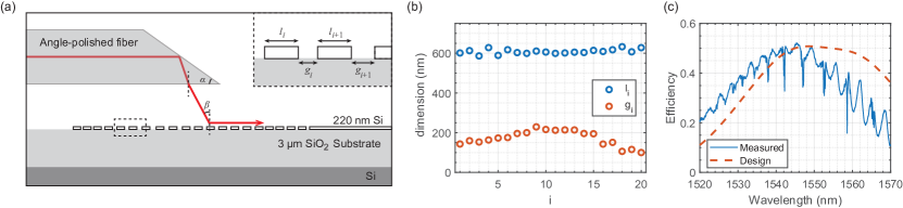
Fig. 8a shows the fiber-optic coupler for the measurement of the optomechanical crystal. Light is guided by an angle-polished single-mode fiber, reflects at the polished surface, and is incident onto a grating coupler. The angle of the fiber is chosen to ensure total internal reflection. Because of the inevitable air gap between the fiber and grating coupler, the incident angle onto the grating coupler is given by . In general, the grating coupler is designed to convert the incident light to a guided wave by satisfying the phase-matching condition , where is the effective refractive index of the grating and is the lattice constant of the grating. It turns out an apodized grating coupler could yield higher coupling efficiency than a uniform grating coupler because of the better mode-matching with the single-mode optical fiber zhao2020design . Thus, we adopt the apodized grating coupler scheme. The apodized grating coupler consists of 20 unit-cells with 40 individual tunable parameters and . The parameters are optimized using a standard inverse design approach molesky2018inverse to maximize the coupling efficiency for different fiber angles. The optimized fiber angle is found to be 35.5° and the corresponding and are shown in Fig. 8b. Fig. 8c shows the simulated transmission and measured device spectrum (inferred from the reflection spectrum). The peak efficiency is observed to be % with a 3-dB bandwidth of nm.
Appendix G Design of photonic crystal mirror
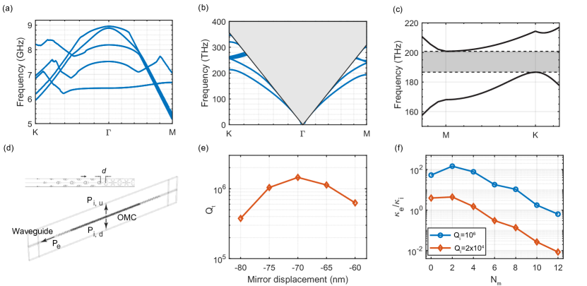
Fig. 9a and b show the full mechanical and optical bandstructure of the nominal optomechanical crystal. The photonic crystal mirror consists of a triangular lattice of cylindrical holes with nm and the same lattice constant nm as the snowflake optomechanical crystal. The simulated band structure with the two lowest TE-like bands (Fig. 9c) shows a complete bandgap from THz (nm) to THz (nm). The photonic crystal mirror effectively suppresses the side-leakage but also perturbs the tail of the standing-wave resonance, inducing wavevector components that fall inside the continuum and causing out-of-plane radiation. We could alleviate such out-of-plane radiation by tuning the separation between the photonic crystal mirror and optomechanical crystal akahane2005fine ; chen2021observation. To simulate this, we take a strip of optomechanical crystal of 25 unit cells as one super-cell and add periodic boundary conditions on the transverse direction, as shown in Fig. 9d. A sufficient number of photonic crystal mirror unit-cells are included and so the total quality factor of the resonance is dominated by the out-of-plane radiation. Fig. 9e shows of the fundamental standing-wave resonance for different . An optimal nm is observed, corresponding to a displacement of the photonic crystal from the nominal lattice constant by nm.
The fabricated optomechanical crystal connects to a waveguide and the external coupling rate could be controlled by the number of phtonic crystal mirror layers between the waveguide and optomechanical crystal. In the simulation, we change the number of phtonic crystal mirror layers on one side (the waveguide side) of the optomechanical crystal super-cell while keeping the other side with a sufficient amount of photonic crystal mirror layers. We have also included four additional tapered mirror layers on the waveguide side. The external and internal quality factors are inferred from the energy flux as
| (23) |
where is the energy flux towards the waveguide and and are out-of-plane energy flux upward and downward, respectively. Fig. 9f shows . The simulation is done for two cases. One case is with a large number of photonic crystal mirrors on the other side of the super-cell such that . In the other case, we purposely reduced the number of photonic crystal mirrors on the other side of the super-cell such that to mimic the fabricated optomechanical crystal. For this case. We find the critical coupling is achieved around .