National Laboratory of Solid State Microstructures and School of Physics, Nanjing University, Nanjing, 210093, China
School of Science, Jiangxi University of Science and Technology, Ganzhou 341000, China
Guangdong Provincial Key Laboratory of Quantum Engineering and Quantum Materials, GPETR Center for Quantum Precision Measurement, SPTE, South China Normal University, Guangzhou 510006, China
Collaborative Innovation Center of Advanced Microstructures, Nanjing University, Nanjing 210093, China
Fabry-Pérot interference in 2D low-density Rashba gas
Abstract
In mesoscopic electronic systems, the Fabry-Pérot (FP) oscillation is observed in various 1D devices. As for higher dimensions, numerous transverse channels usually lead to dephasing that quenches the overall oscillation of the conductance. Up to now, the FP oscillation in 2D electronic systems is only reported in graphene-based devices and very recently, the pn junctions of inverted InAs/GaSb double quantum well [Phys. Rev. X 10, 031007 (2020)]. In the latter, the band shape of a sombrero hat plays an essential role, which introduces a novel mechanism of electron-hole hybridization for the 2D FP oscillation. In this work, we propose that such a scenario can be generalized to the 2D planar junction composed of low-density Rashba gas, where the band bottom possesses sombrero hat shape as well. We show that the backscattering between the outer and inner Fermi circles dominates the FP interference and significantly suppresses the dephasing effect between different transverse channels, which leads to a visible oscillation of the tunneling conductance. Specially, the visibility of the oscillating pattern can be enhanced by applying interface barriers, which in contrast to that in the InAs/GaSb double quantum well. Our results provide a promising way for the implementation of the FP oscillation in the 2D electron gas.
1 Introduction
Fabry-Pérot (FP) interference occurs between a pair of reflectors, where a wave propagating in between can undergo multiple reflections with different coherent paths interfering with each other. In optics, it is manifested as the fine structure of the interference patterns of the transmissivity as the distance between reflection surfaces varies. As a universal property of coherent waves, FP oscillation generally exists in various physical systems. In mesoscopic systems for example, the coherent electronic wave also exhibits FP interference, which usually manifests as the conductance oscillation with varying energy. The FP oscillation has been observed in several 1D systems, such as carbon nanotubes [1] and quantum Hall edge states [2, 3, 4, 5, 6]. However, it is quite challenging to realize such a novel effect in higher dimensions, because the existence of numerous transverse channels with different oscillating phases can easily quench the overall signature. One exception is the 2D pnp (or npn) junctions made of single-layer [7, 8, 9, 10] or multi-layer graphene [11, 12], in which the Klein or anti-Klein tunneling together with the unique Dirac dispersion enable the survival of FP oscillation after averaging over all transverse channels.
Most recently, FP oscillation was observed in another 2D system, the pnp junctions of the inverted InAs/GaSb double quantum well [13] which is well known for its nontrivial band topology [14, 15, 16, 17]. Its band structure is featured by the band inversion and electron-hole hybridization [18, 19, 20, 21]. Different from a conventional 2D band structure, such a band shape resembles a sombrero hat, which is key to the observation of 2D FP oscillation [13]. Specifically, the electron (e) and hole (h) states coexist close to the band bottom and the e-h reflection dominates the FP interference. It significantly reduces the phase difference of oscillation between the transmission functions of different transverse channels and gives rise to visible oscillation of the conductance, in contrast to the conventional e-e reflection. This discovery expanded the field of electron optics to include materials that exhibit band inversion and hybridization. Notably, the band shape similar to the sombrero hat can be found in various condensed matter systems, of which the typical example is the 2D electron gas with Rashba spin-orbit coupling [22] [see fig. 1]. Then a natural question that arises is whether the FP oscillation can be observed in these systems as well.
In this work, we give an affirmative answer to this question by studying the FP interference in the 2D junctions of the low-density Rashba gas. Specifically, for the normal metal-Rashba gas-normal metal (NRN) junctions, reflections that take place between the outer and inner Fermi circles induce visible FP oscillation in the total transmission function, which can be probed by the oscillation of the differential conductance. Moreover, we found that the interface barriers can enhance the visibility of the oscillation pattern due to the helical spin texture of the Rashba gas. Our findings pave the way towards the implementation of 2D FP interference in a new electronic system.
This paper is organized as follows: We study the scattering problem in in the NRN junctions and analyze the FP oscillation of the conductance in the second section. The effect due to the magnetic field is investigated in the third section. Finally, the discussion on the experimental implementation of our proposal and a brief summary are given in the fourth section.
2 FP interference in NRN junctions
We consider the 2D NRN junctions lying in the - plane which consist of the low-density Rashba gas sandwiched by two pieces of normal metals with spin degeneracy; see fig. 1(c). The whole system can be captured by the effective model as
| (1) |
where and describe the normal metal and the Rashba gas, respectively, with the Heaviside unit step function, is the momentum and and are the effective masses. The energy in the normal metal is measured from the chemical potential . In the middle region, a gate voltage is applied to adjust the energy of the bands, are Pauli matrices for electronic spin and is the Rashba coefficient, which can reach as high as 2 in the experiment [23]. The interface barriers are simulated by two -function potentials with strengths .
Solving yields two bands with and . The bands exhibit a spin dependent splitting as shown in fig. 1(a). Notably, the band bottom of the Rashba gas resembles that of the inverted InAs/GaSb quantum well [13], which is key to the 2D FP interference. Here, we focus on the low-density limit of the Rashba gas such that the Fermi energy only intersects the branch. In the following, we refer the inner and the outer Fermi circles as h and e, respectively, by noting that the velocity and the momentum have opposite sign for the inner Fermi circle [cf. figs. 1(a) and 1(b)].
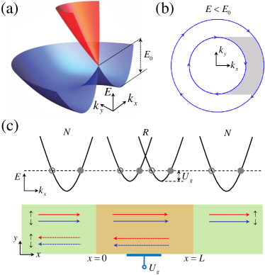
Next we solve the spin resolved scattering problem in the NRN junction. In the normal metal, no spin-orbit coupling exists so the energy bands are spin degenerate. In the middle region, the band splitting introduces two branches of scattering states in the Rashba gas; see fig. 1(c). Two Fermi circles have the same/opposite winding direction of the spin as the Fermi energy lies below/above the central band touching point. Suppose that the size of the junction along the direction is much larger than the Fermi wave length so that is conserved during scattering. For an electron with a spin and an energy incident from , the wave functions in the left, the middle and the right regions are
| (2) |
where and are the amplitudes of the reflected and transmitted waves with spin , respectively. The coefficients with and correspond to four scattering waves in the middle region. The spinor parts of the scattering waves in the Rashba region is defined as and . The -direction momentums in different regions are and , respectively.
All the scattering coefficients can be solved by the boundary conditions at two interfaces as
| (3) |
where are the reduced barrier strengths defined by the Fermi wave vector . The total reflection and transmission probabilities are obtained as and from which the current conservation condition for each transverse channel can be verified.
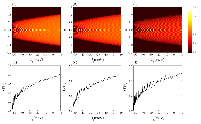
The FP interference for a 2D junction can be revealed by the oscillation pattern of the transmission as a function of the gate voltage in various transverse modes labeled by the incident angle ; see figs. 2(a)-(c). The oscillation patterns share the same feature as those in the InAs/GaSb double quantum well [13]. It contains two typical regions marked with the bright central stripes and the darker outlying ones indicating the maximum transmissions. The key observation is that the transmission functions for energies close to the band bottom exhibit a weak -dependence which can be tracked by the bright stripes in figs. 2(a)-(c). This part of interference pattern corresponds to the e-h and h-e reflections between the outer and inner Fermi circles as shown in fig. 1(a), the same as that the InAs/GaSb double quantum well [13]. It results in a weak dependence of the momentum transfer and accordingly, the accumulated FP phase on the transverse momentum , which facilitates the 2D FP oscillation [13]. On the contrary, for the e-e and h-h reflections that occur within the inner or outer Fermi circles for higher energies, varies significantly with which only contribute a smooth background of the conductance.
The weak dependence of on indicates that a visible oscillation will remain after summing up the transmission probabilities over all transverse channels, which can be probed by the differential conductance
| (4) |
where is the conductance for the normal metal stripe with a width . The incident energy is set to and the integral interval is bounded by the critical incident angle . The numerical results of as a function of the gate voltage are shown in figs. 2(d)-(f), which exhibit a visible oscillation of the conductance below the band crossing energy of the Rashba gas (meV).
Apart from the similarity to the InAs/GaSb quantum well, the Rashba gas has its unique feature. Note that two Fermi circles below the Dirac point possess the same spin winding [cf. fig. 1(a)], so that the e-e (h-h) reflection is strongly suppressed for small incident angle due to the opposite spin polarization of the incident and reflected states. As a result, the e-h (h-e) reflection dominates the FP interference with a nearly conserved spin. Such a scenario is expected to be robust against interface barriers. In figs. 2(a)- 2(c), one can see that the interface barriers make the transmission stripes even sharper, which indicates that the e-h scattering is enhanced by the interface barrier while the opposite spin orientation for the e-e (h-h) scattering still prohibit its occurrence. Accordingly, the visibility of the conductance oscillation increases as well despite a reduction of its magnitude; see figs. 2(d)- 2(f).
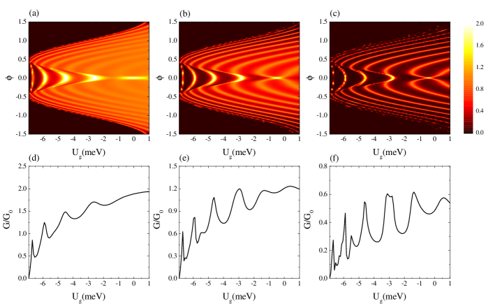
In the above calculation, we use a large value for , i.e., , which was experimentally observed in a surface alloy [23]. It is more promising that an experiment to observe this effect would be based on some sort of semiconductor heterostructure, which would feature values about an order of magnitude lower (i.e. ). The most promising materials and relative parameters are listed in table 1, where the Rashba energy of split states has been computed from the experimentally accessible quantities and . Thus we calculate the transmission coefficient and conductance with as shown in fig. 3. As one can see, the conductance spectra exhibit a distinct oscillation, which can be enhanced by the interface barriers. The main effect due to a smaller Rashba strength is a reduction of the number of oscillating peaks as shown in figs. 3(d)- 3(f). We conclude that the FP interference and corresponding conductance oscillations can still be observed for values of about an order of magnitude lower.
| Material | |||
|---|---|---|---|
| () | () | () | |
| 0.81 | 0.13 | 89.8 | |
| heterostructures[28] | |||
| heterostructures | 0.25 | 0.037 | 2.25 |
| along Au(111) surface[29] | |||
| Te-terminated | 0.1489 | 0.35 | 119.7 |
| surface of BiTeI[30] |
3 magnetic field effect
We now discuss the effect of the magnetic field on the FP oscillations, which is usually investigated simultaneously in the experiment of 2D electronic FP oscillation. Since the transverse momentum is approximately conserved during scattering, it can be chosen as a parameter. In this way, the 2D system is decomposed into a set of 1D channels labeled by . The Landau gauge is adopted so that the Peierls substitution retains the conservation of . We perform numerical simulation on a square lattice through the substitutions of and , with the fictitious lattice constant. Keeping a parameter and performing Fourier transformation yields the Rashba Hamiltonian on the discrete lattice as
| (5) |
where is the Fermi operator on site with both spin components and and are block matrices with the explicit form of
| (6) |
The lattice model for the normal metal can be obtained in a similar way, which writes
| (7) |
where denotes the spinful fermion operator in the normal metal, and .
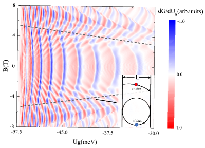
For a given , the transmission probability is calculated using the KWANT package [24]. A summation of the transmissions of all channels yields the conductance of the 2D junction. We plot the modulation of the oscillation pattern of the differential conductance induced by the magnetic field in fig.4. For a small , the conductance pattern exhibits a weak -dependence especially for the energy around the band bottom. As increases, the tripes tracking the resonance bend toward lower . Comparing at and that at , there is an interchange of the minima and maxima except for certain additional structures, which indicates a phase shift of in the oscillation pattern of the conductance. As increases further, the oscillation pattern tends to be less visible accompanied by a reversal of the bending direction of the resonant stripes. The two different regimes correspond to e-h reflection and e-e (h-h) reflection, respectively, and a boundary between them is marked by the dashed lines in fig.4. In the semiclassical picture, the cyclotron motion of an electron possesses a radius of , with the Fermi wave vector . The holes (h) in the inner Fermi surface possess a smaller cyclotron radius (cf. fig. 1), which decreases with increasing . Once it decreases to the threshold at a critical field , where is the length of the Rashba region [cf. fig. 1(c)], the electron in the inner Fermi surface cannot transmit through the Rashba region, see the inset of fig. 4. As a result, the e-h reflection is suppressed, which quenches the FP oscillation of the conductance. The critical magnetic field as a function of the gate voltage is plot by the dashed lines in fig. 4.
4 Discussions and summary
We would like to discuss the experimental implementation of our proposal. The 2D low-density Rashba gas is a crucial building block in our proposal, which has been achieved in the heterostructures [25, 26, 27]. These systems are fabricated by the band engineering techniques taking advantage of the interfacial/low-dimensional effects, in which the Rashba coefficient can be precisely controlled by an electric field. Moreover, the physical parameters such as the chemical potential in such heterostructures can be easily tuned by a gate voltage. For example, it was reported that the Rashba energy and the Fermi energy in a two-dimensional electron gas can be tuned by a controlled change of stoichiometry in an artificial surface alloy [23], whose Rashba parameter can reach several . These progresses pave a way to realize our proposal in the NRN junctions.
In summary, we propose to realize the FP interference in the 2D low-density Rashba gas. The low-density Rashba gas exhibits a unique spin texture, resulting in a small probability of reflection within the inner and outer Fermi circles, which favors reflections between the inner and outer Fermi circles that determine the FP interference. For a spin-orbit coupled system, a larger Rashba enengy of split states has a more profound effect on the FP interference. According to the results from our models, there is a FP oscillation of the conductance versus gate voltage in the 2DEG NRN junction, which benefits from the interface barriers. With increasing the interface barriers, the reflections between the outer and inner Fermi circles are further enhanced, and thus the FP interference becomes more visible. Therefore, the resolution of the FP interference in response to the interface barriers can be an observable to detect the unique spin textures of the low-density rashba gas. Moreover, the dependence of magnetic field is included. The lines of constant transmission bend toward lower with increasing the magnetic field, and a phase shift of occurs at certain . Further increasing the magnetic field will suppress the interference phenomenon. Based on the above results, we perfected the field of electron optics to include materials that exhibit band hybridization.
Acknowledgements.
We thank Oded Zilberberg and Antonio Štrkalj for helpful discussions. This work was supported by the National Natural Science Foundation of China under Grant No. 12074172 (W.C.), the startup grant at Nanjing University (W.C.) and the Excellent Programme at Nanjing University.References
- [1] \NameLiang W., Bockrath M., Bozovic D., Hafner J. H., Tinkham M., Park H. \REVIEWNature4112001665.
- [2] \Namevan Wees B. J., Kouwenhoven L. P., Harmans C. J. P. M., Williamson J. G., Harris J. J. \REVIEWPhys. Rev. Lett.6219892523.
- [3] \NameJi Y., Chung Y., Sprinzak D., Heiblum M., Mahalu D., H. Shtrikman \REVIEWNature4222003415.
- [4] \NameOfek N., Bid A., Heiblum M., Stern A., Umansky V., Mahalu D. \REVIEWPNAS10720105276.
- [5] \NameMcClure D. T., Zhang Y., Rosenow B., Levenson-Falk E. M., Marcus C. M., Pfeiffer L. N., West K. W. \REVIEWPhys. Rev. Lett.1032009206806.
- [6] \NameNakamura J., Fallahi S., Sahasrabudhe H., Rahman R., Liang S., Gardner G. C., Manfra M. J. \REVIEWNature Physics152019563.
- [7] \NameYoung A. F. Kim P. \REVIEWNature Physics52008222.
- [8] \NameRickhaus P., Maurand R., Liu M. H., Weiss M., Richter K., Schönenberger C. \REVIEWNature Communications420132342.
- [9] \NameGrushina A. L., Ki D.-K., Morpurgo A. F. \REVIEWAppl. Phys. Lett.1022013223102.
- [10] \NameOksanen M., Uppstu A., Laitinen A., Cox D. J., Craciun M. F., Russo S., Harju A., Hakonen P. \REVIEWPhys. Rev. B892014121414(R).
- [11] \NameCampos L. C., Young A. F., Surakitbovorn K.,Watanabe K., Taniguchi T., Jarillo-Herrero P. \REVIEWNature Communications320121239.
- [12] \NameVarlet A., Liu M.-H., Krueckl V., Bischoff D., Simonet P., Watanabe K., Taniguchi T., Richter K., Ensslin K., Ihn T. \REVIEWPhys. Rev. Lett.1132014116601.
- [13] \NameKaralic M., Trkalj A., Masseroni M., Chen W., Zilberberg O. \REVIEWPhys. Rev. X102020031007.
- [14] \NameLiu C., Hughes T. L., Qi X.-L., Wang K., Zhang S.-C \REVIEWPhys. Rev. Lett.1002008236601.
- [15] \NameSuzuki K. O. K., Harada Y., Muraki K. \REVIEWPhys. Rev. B872013235311.
- [16] \NameDu L., Knez I., Sullivan G., Du R.-R. \REVIEWPhys. Rev. Lett.1142015096802.
- [17] \NamePribiag V. S., Beukman A. J. A., Qu F., Cassidy M. C., Charpentier C., Wegscheider W., Kouwenhoven L. P. \REVIEWNature Nanotechnology102015593.
- [18] \NameAltarelli M. \REVIEWPhys. Rev. B281983842.
- [19] \NameLakrimi M., Khym S., Nicholas R. J., Symons D. M., Peeters F. M., Mason N. J., Walker P. J. \REVIEWPhys. Rev. Lett.7919973034.
- [20] \NameYang M. J., Yang C. H., Bennett B. R., Shanabrook B. V. \REVIEWPhys. Rev. Lett.7819974613.
- [21] \NameCooper L. J., Patel N. K., Drouot V., Linleld E. H., Ritchie D. A., Pepper M. \REVIEWPhys. Rev. B57198311915.
- [22] \NameBychkov Y. A., Rashba É. I. \REVIEWJetp Lett.39198478.
- [23] \NameAst C. R., Pacilé D., Moreschini L., Falub M. C., Papagno M., Kern K., Grioni M. \REVIEWPhys. Rev. B772008081407(R).
- [24] \NameGroth C. W., Wimmer M., Akhmerov A. R., Waintal X. \REVIEWNew Journal of Physics162014063065.
- [25] \NameNitta J., Akazaki T., Takayanagi H., Enoki T. \REVIEWPhys. Rev. Lett.7819971335.
- [26] \NameWinkler R. \BookSpin-Orbit Coupling Effects in Two-Dimensional Electron and Hole Systems \Vol191 \PublSpringer,Berlin Heidelberg \Year2003
5 Inversion-Asymmetry-Induced Spin Splitting
.