19(3.5,3) Due to the responsible disclosure, parts of the technical report have been redacted.
Brokenwire : Wireless Disruption of CCS Electric Vehicle Charging
Abstract
We present a novel attack against the Combined Charging System, one of the most widely used DC rapid charging technologies for electric vehicles (EVs). Our attack, Brokenwire, interrupts necessary control communication between the vehicle and charger, causing charging sessions to abort. The attack can be conducted wirelessly from a distance, allowing individual vehicles or entire fleets to be disrupted stealthily and simultaneously. In addition, it can be mounted with off-the-shelf radio hardware and minimal technical knowledge. The exploited behavior is a required part of the HomePlug Green PHY, DIN 70121 & ISO 15118 standards and all known implementations exhibit it.
We first study the attack in a controlled testbed and then demonstrate it against seven vehicles and 18 chargers in real deployments. We find the attack to be successful in the real world, at ranges up to 47 m, for a power budget of less than 1 W. We further show that the attack can work between the floors of a building (e.g., multi-story parking), through perimeter fences, and from ‘drive-by’ attacks. We present a heuristic model to estimate the number of vehicles that can be attacked simultaneously for a given output power.
Brokenwire has immediate implications for many of the around 12 million battery EVs on the roads worldwide — and profound effects on the new wave of electrification for vehicle fleets, both for private enterprise and crucial public services. As such, we conducted a disclosure to the industry and discussed a range of mitigation techniques that could be deployed to limit the impact.
1 Introduction


Replacing††† Both authors contributed equally to this paper. petrol and diesel vehicles with electric vehicles (EVs) has been one of the main approaches to cut down the global greenhouse-gas emission. As a result, many countries have committed to completely ban the sale of vehicles with combustion engines within the next decade [31, 37, 42]. The US government announced the transition of their 645,000 vehicles to a fully electric fleet [20]. The National Health Service in the UK plans to purchase fully electric ambulances [30]. In addition to governmental institutions, delivery companies are moving towards EVs, too. Amazon started switching to electric delivery vans [1] and electric trucks [29]. The United States Postal Service (USPS), Royal Mail, United Parcel Service (UPS), and DPD announced the transition to fully electric delivery vans [65, 24, 61, 21].
Nevertheless, one disadvantage of EVs is that they are slower to refuel than fossil-fuel vehicles. Therefore, the successful transition to all-electric vehicles requires a comprehensive and harmonized charging infrastructure that enables a vehicle to be charged in a short time [64]. This is achieved by increasing the charging capabilities of the charging stations, also known as Electric Vehicle Supply Equipment (EVSE), and building so-called charging hubs that enable the charging of multiple cars simultaneously. Figure 1 shows such a charging hub, the largest currently in operation in Europe.
Direct Current (DC) charging has become the de-facto standard to enable rapid charging. For safety and efficiency reasons, the high-power DC charging stations rely on communication with the vehicle to exchange vital information, such as maximum voltage, required current, and the State of Charge (SoC). This means the availability of the communication link is crucial for the charging session and any disruption of the communication, intentional or unintentional, will result in the charging process being aborted for safety reasons [41].
The fastest-growing DC charging standard, already dominant across North America and Europe, is the Combined Charging System (CCS) [38, 36]. CCS provides a high-bandwidth IP link via power-line communication (PLC) for the communication between the EV and EVSE. This brings benefits in terms of reusing commodity technologies and affording capacity for additional services, such as automatic billing and demand-response charging, in addition to the crucial charging session control [39].
However, it is known that PLC, as used in CCS charging, unintentionally leaks communication signals via the charging cable [4] and it has been shown in other settings that PLC is susceptible to electromagnetic interference [49].
In this paper, we present Brokenwire, an attack that exploits the combination of the susceptibility of PLC to intentional electromagnetic interference (IEMI) and the use of unshielded charging cables. We demonstrate that the charging communication required by CCS can be disrupted wirelessly — causing the charging session to abort and leaving the vehicle and the EVSE in an error state.
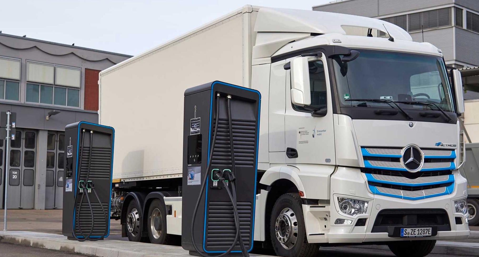
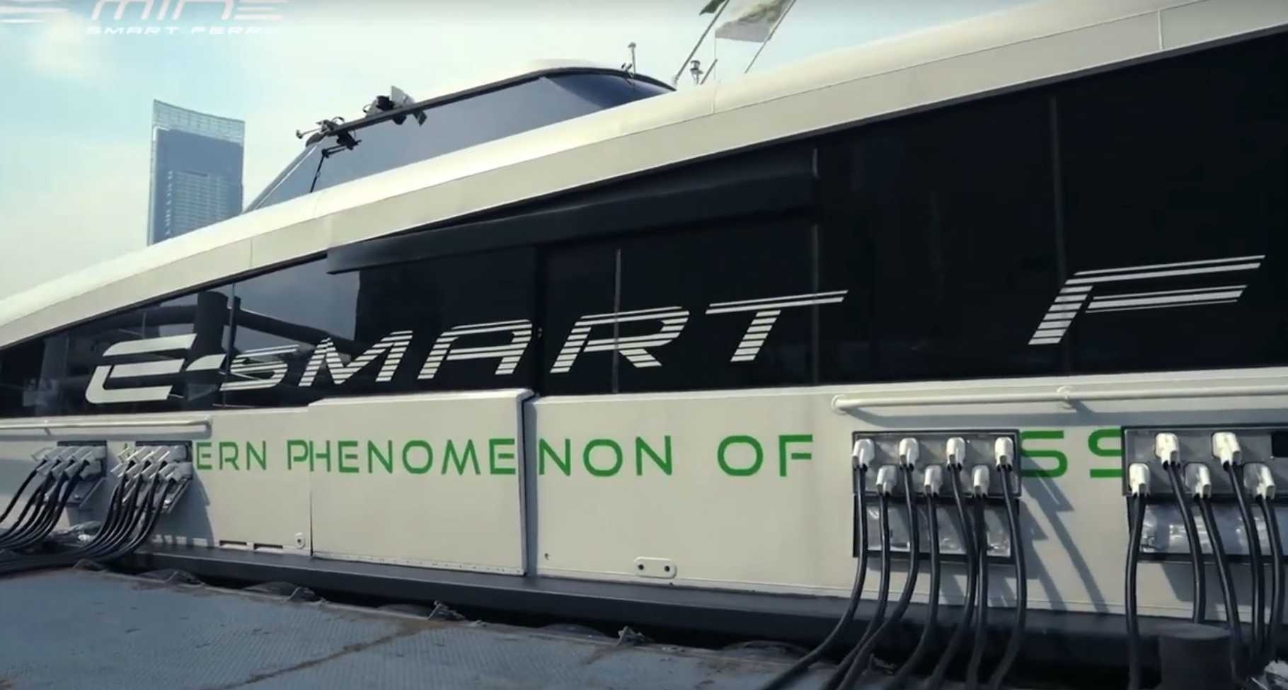
Since CCS is becoming increasingly popular as a charging standard for a wide range of EVs — beyond solely passenger vehicles — the Brokenwire attack has immediate implications to a variety of other applications as well, such as buses [62], heavy-duty trucks [16], aircraft pushback tractors [27], private boats [2], public ferries [52] and even airplanes [28]. A handful of examples of vehicles that use CCS and are vulnerable to the Brokenwire attack are shown in Figure 2. Moreover, CCS is also poised to play a decisive role in the future of the power grid [10]. As the energy generated from renewable resources increases, the need for electricity storage has become more important than ever. Bi-directional charging in combination with Vehicle-to-Grid (V2G) communication will enable vehicles to act as energy storage to buffer excess energy and feed it back into the grid to meet peak demand [55]. First trials of this approach have recently started in different countries, for example, Germany [8], Switzerland [33] and the UK [7]. As such, EVs with CCS will also soon play a significant role in the stability of the power grid, intertwining them even further into critical infrastructure. Our work highlights a severe design flaw in the use of PLC for charging communication that leaves millions of vehicles, some of which are in constant use within critical infrastructure sectors, vulnerable.
Contributions
-
1.
We discovered a vulnerability in the most widely adopted DC rapid charging standard in Europe and North America leaving millions of EVs vulnerable.
-
2.
We demonstrate the Brokenwire attack in an extensive evaluation in both controlled laboratory and real-world environments.
-
3.
We analyze the effects of the Brokenwire attack and its real-world implications.
-
4.
We propose different countermeasures, including a cheap and easy-to-deploy hardware approach that makes the attack orders of magnitude harder to conduct.
2 Background
This section describes the underlying technical concepts and terminologies of today’s charging standards, which help better understand the Brokenwire attack.
2.1 Electric Vehicle Charging
Charging an electric vehicle can be done with either Alternating Current (AC) or Direct Current (DC). While for AC charging the car has to be equipped with a rectifier that converts the alternating current to direct current, for DC charging this process is outsourced to the charging station. To reduce the additional weight from the rectifier, its capacity is limited, which caps the maximum charging power for AC charging to around 22 kW. In contrast, DC charging enables high-power charging, often referred to as rapid charging, with up to 350 kW. Therefore, for recharging a vehicle in a short time frame, DC chargers are the first choice.
In addition to the Combined Charging System, three competing DC charging standards currently exist — CHAdeMO, Tesla’s supercharger, and GB/T 20234. While Tesla’s supercharger is a proprietary technology, CHAdeMO was developed by car manufacturers from Japan as an alternative to CCS [17]. Similarly, GB/T 20234 was designed for the Chinese market. The main difference between these standards and CCS is the use of CAN for the charging communication rather than PLC. However, more and more non-European car manufacturers using CHAdeMO, such as Kia, Nissan, and Hyundai, moved to CCS [46, 14, 54]. Moreover, Tesla started using CCS with the introduction of the European version of their Model 3 in 2018 [47] and recently announced an updated version of their Model S and Model X for the European market, which will be equipped with a CCS socket by default and no longer require an adapter [48]. Therefore, it is likely that in the near future, CCS will become the primary global charging standard [26]. As such, our work focuses on CCS only and will discuss the relevant details about its underlying technical details in the subsequent section.
2.2 Combined Charging System
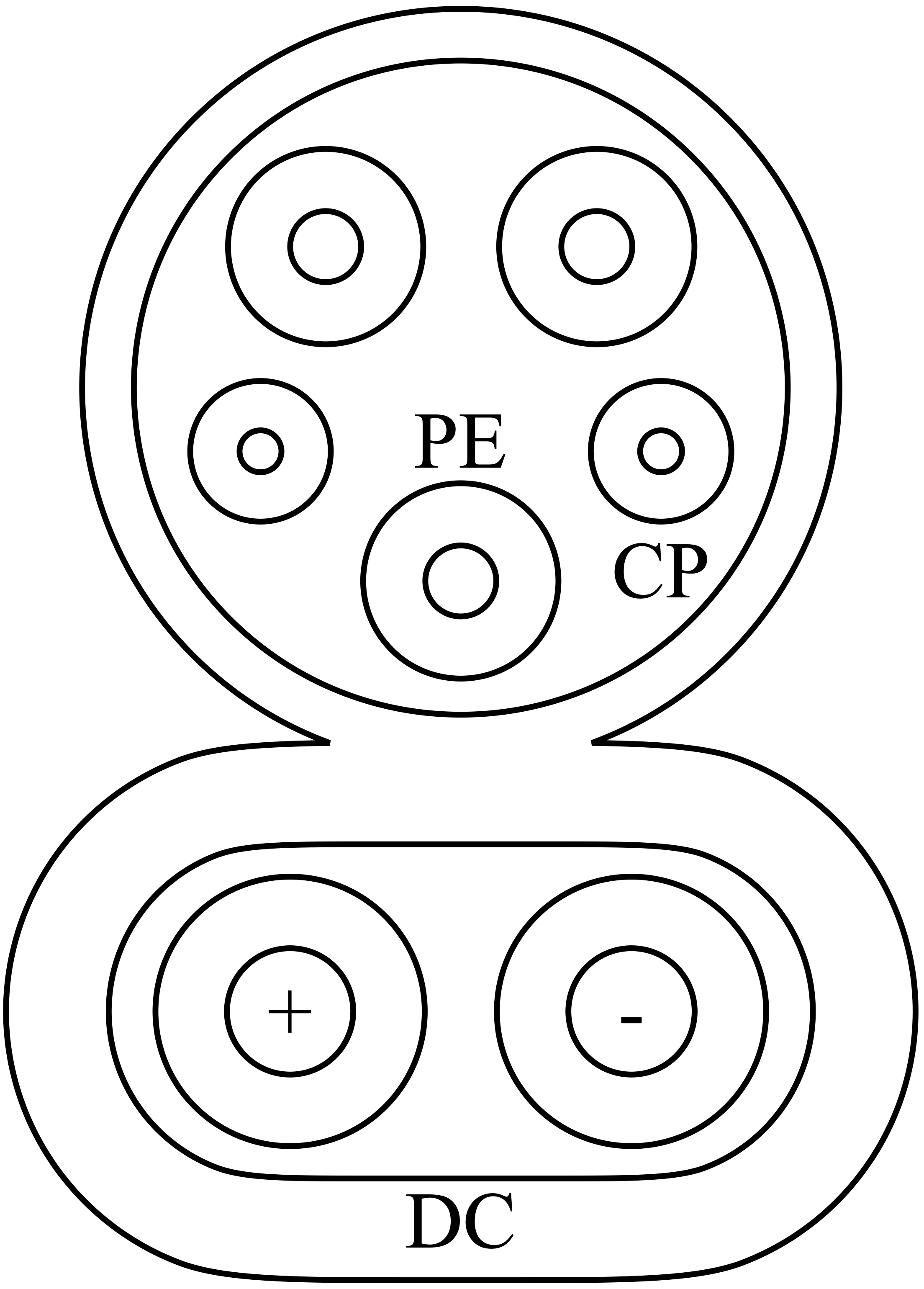
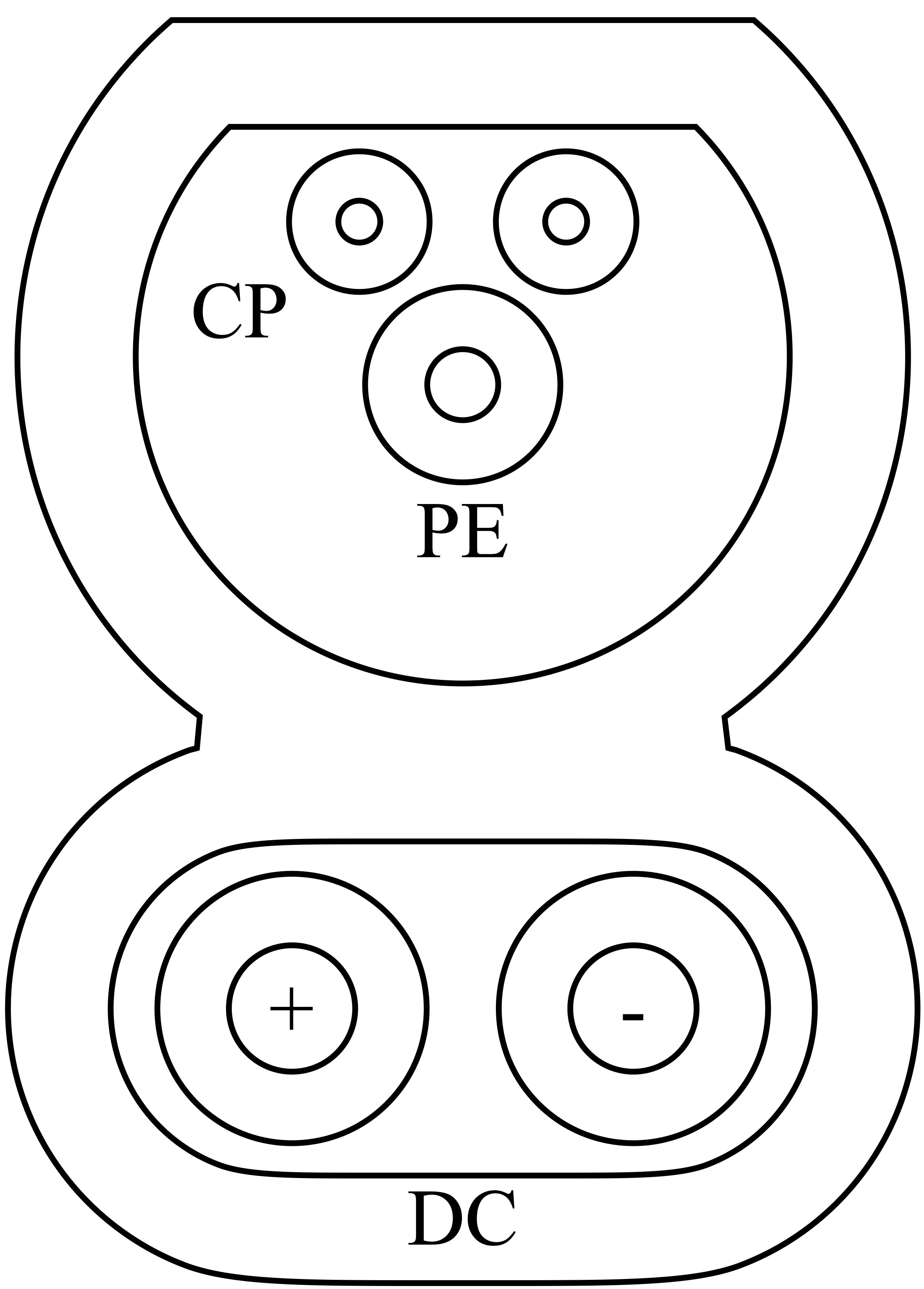
The charging technology standardized as the Combined Charging System — the name presented to a vehicle user — is, in fact, a collection of multiple technical standards, assembled by the Charging Interface Initiative e.V. (CharIN e.V.), a non-profit association founded by a consortium of different stakeholders, such as automobile manufacturers, component suppliers and charging station vendors. In this paper, we focus on communication between the EV and the EVSE, which is governed by the ISO 15118 series of standards111Previously by a simplified subset in DIN 70121, which provides limited capabilities but is functionally identical for underlying communication. [39]. Depending on the geographical region, CCS uses different plug types, which are illustrated in Figure 3. In North America Combo 1 and in Europe Combo 2 is used. While the connector arrangement differs slightly between the two types, the underlying technology is the same. As the name suggests, PLC usually uses the main power lines as a transmission medium. However, in the case of CCS, the two separate wires, the Control Pilot (CP) and Protective Earth (PE) are used. The actual direct current is delivered by the two large conductors at the bottom of the plug.
For backward compatibility, a basic communication scheme using a pulse-width modulation (PWM) protocol defined in the IEC 61851 standard [34] is used when initializing the charging process. Upon successful initialization of this communication, a high-bandwidth IP link is established and control is handed to it. The vehicle and charger then engage in an application-layer protocol to control charging. This communication must be maintained throughout the charging session for a variety of reasons, the most important of which is fault detection. If the communication is lost, the ISO 15118 standard requires the CCS charging session to halt immediately and cease power transfer, upon which the EV and EVSE choose whether or not to attempt to start a new session from the beginning (or, in limited cases, continue charging using the basic pulse–width modulation protocol) [40, 41]222This depends on various factors including the payment method used for the charging. We observed no instances of this fallback occurring in practice..
In addition to the main charging control loop, CCS also provides a range of additional capabilities using the IP link. One feature, known as ‘Plug & Charge’, enables automatic billing without the user authorizing a transaction manually [39] — and is currently appearing in the newest EVs and EVSE installations. Trials of ‘Vehicle-to-Grid’ capabilities, in which vehicles can change their charging profile in response to power availability and even provide bidirectional power transfer, are at an advanced stage and these capabilities are expected to be publicly deployed shortly [67].
The Combined Charging System is principally intended only for light vehicles. While it is used directly in some much larger vehicles [52, 9], derivative standards exist that are better suited to these uses and it is expected that these will be adopted more in the future. The SAE J3105 standard describes systems for charging electric buses using a range of connector options underpinned by ISO 15118 [13]. Meanwhile, the new Megawatt Charging System (MCS) standard has been recently completed by the same standardization body as CCS, specifically designed to accommodate the needs of heavy vehicles, such as freight trucks [11]. At the time of writing, trials have been run with 3.75 MW of charging power [11]. We describe in Section 7 how our work is relevant for these standards, too.
2.3 HomePlug Green PHY
The high-bandwidth IP link used for communication in ISO 15118 is provided by the HomePlug Green PHY (HPGP) power-line communication technology [41]. HPGP is a derivation of the earlier HomePlug AV family of in-home LAN technologies. The HPGP standard is publicly available at no cost [32], and is discussed in detail in [4] and [5].
In brief, HPGP uses an Orthogonal Frequency-Division Multiplexing (OFDM) physical-layer operating in the 2 – 28 MHz band and modulating data onto (typically) 917 unmasked subcarriers spaced 24.414 kHz apart. The technology provides a set of communication modes that trade throughput vs. reliability with maximum speeds of 3.77, 4.92 (default), and 9.84 Mbps.
The work in [4] also describes a notable challenge with HPGP PLC: its propensity to leak communication signals from the charging cable. It has also been noted in [49] that the related HomePlug AV technologies are vulnerable to interference emitted in the same frequency range by broadcasting and wireless communication systems. This vulnerability was carried across to the HPGP technology and presents a risk of cross-talk between different vehicle-charger pairs in adjacent parking bays. It is possible that a vehicle would begin communicating, not with the charger that it is physically connected to, but with a nearby charger that happened to respond first, but is actually communicating via leaked signals. The HPGP specification implements the Signal Level Attenuation Characterisation (SLAC) protocol to mitigate this, in which the vehicle and charger exchange sounding messages to determine which are connected directly (thereby experiencing the least attenuation of their sounding messages) and which are being inadvertently overheard due to cross-talk [32].
3 Threat Model
The overarching goal of our considered attacker is the disruption of charging sessions for one or more EVs. We group possible scenarios into three categories:
Single vehicle
In this case, a specific vehicle is targeted. This may be done as an attack on the owner, to make it difficult for them to travel, either at home or a remote location, thus exposing them to inconvenience or making them vulnerable to further attack. Alternatively, it may be intended as an attack on the vehicle; immobilizing it at a remote location, from which it could be stolen if the driver leaves to obtain support.
Fleet denial
In this case, a specific organization is targeted and their vehicles immobilized en masse. This may be a delivery or transport business, in order to cause financial loss or harm supply chains. Alternatively, the organization may represent a public service, such as buses, taxis, a police force, or ambulances, with the attack impacting local citizens.
Unspecific disruption
In this case, as many vehicles as possible are attacked, without regard to who owns or operates them.
There may be an alternative attack rationale, such as harming the business of a charging service provider or influencing the local power grid through manipulation of the high power consumption of EVs (and their proposed future use as storage batteries).
Alternatively, the motivation may simply be spite — blocking or vandalizing vehicle chargers due to a strong dislike of EV technologies has been documented in countries worldwide.
We consider an attacker who seeks to conduct their disruption with stealth, speed, and scalability. The simplest ways to interrupt charging are to operate an emergency cutout switch or to damage the vehicle, cable, or charger. However, such approaches require direct access, which is risky for perpetrators and mitigated with physical barriers or surveillance. Furthermore, the same process must be repeated for each targeted vehicle or charger, with commensurate repeated risks.
In contrast, Brokenwire enables an adversary to disrupt charging sessions at scale and from a safe, reasonable distance without interacting directly with the target(s). The attack can be performed from beyond the line of sight of potential CCTV cameras, concealing the attacker’s presence. In addition, physically-secured charging parks located behind a fence or wall are vulnerable. The adversary can either execute the attack in person from a nearby location or deploy a device at the target site and control it remotely.
Since the entry barrier for carrying out the attack is low, our threat model considers a malicious actor with only access to off-the-shelf hardware that can easily be purchased online. At a minimum, this constitutes a software-defined radio and an antenna, with additional power amplifiers potentially being used to increase transmission power and, hence, range. We assume that an attacker can generate or capture the required attack signal — which they may subsequently distribute to others to further reduce the barrier to entry.
4 The Brokenwire Attack
This section has been removed.
Videos and pictures of the attack are available on our website https://brokenwire.fail.
5 Lab Evaluation
We present, in this section, the results of our experiments with the attack in a controlled laboratory environment.
5.1 Experimental Setup
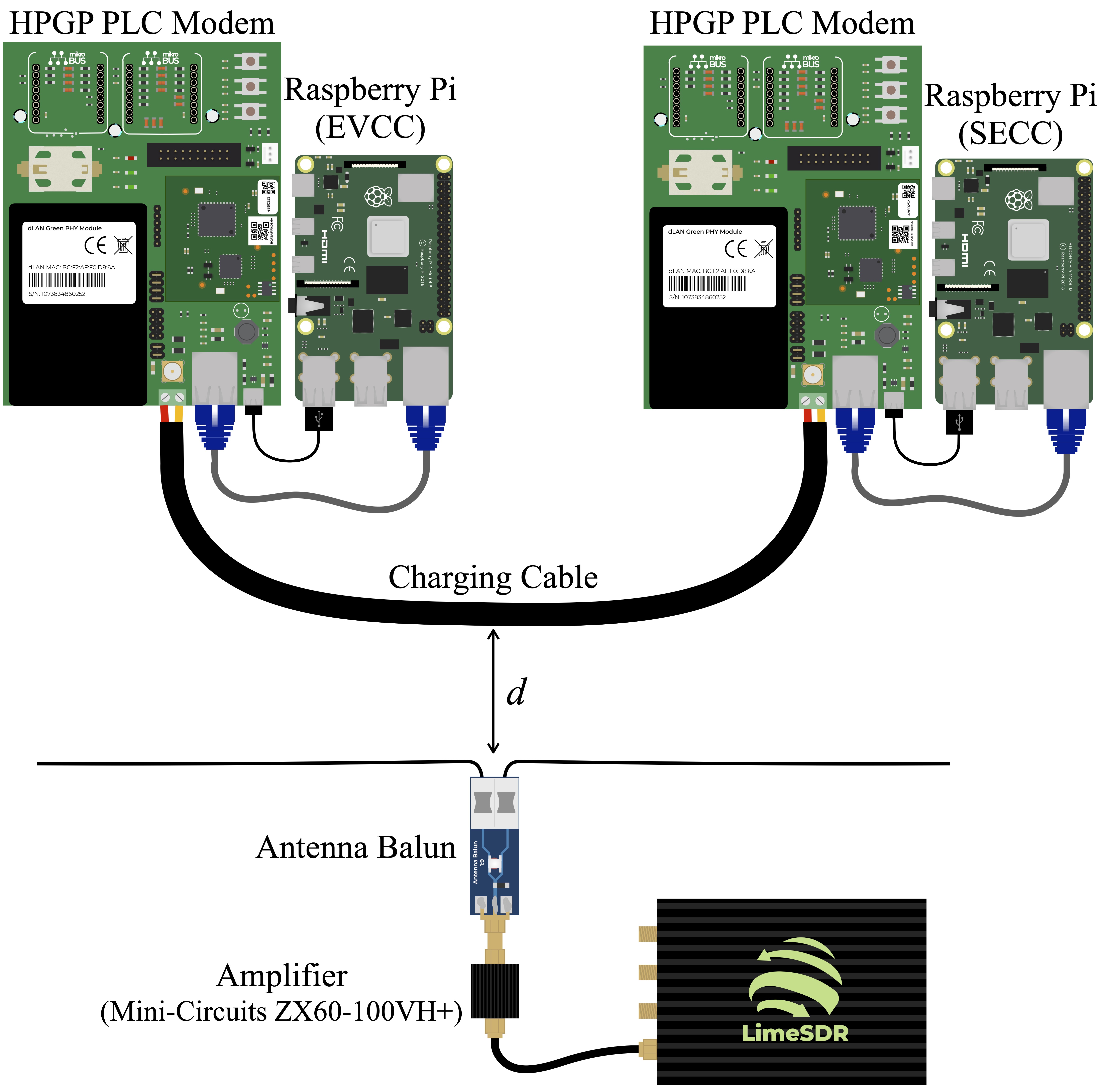
We evaluated the attack under controlled laboratory conditions, using a testbed composed of two PLC HomePlug Green PHY evaluation boards from Devolo (dLAN Green PHY eval board II) [19]. The boards were equipped with the same Qualcomm QCA7000 chips, as they are used for communication in EVs and DC high-power charging stations [69]. The two HPGP evaluation boards were connected via a 4 m long copper wire with two flex cores (2 1.5mm2), one for the Control Pilot and one for Protective Earth, the same cable structure found in CCS charging cables. The cable length corresponded roughly to the same length found at most DC rapid chargers. Each PLC modem was connected to a RaspberryPi via Ethernet, which acted as Electric Vehicle Communication Controller and (EVCC) and Supply Equipment Communication Controller (SECC).
On the attacker side, we used a LimeSDR as the transmitter connected to a 1 W amplifier (Mini-Circuits ZX60-100VH+). We used GNURadio to operate the LimeSDR and emit the malicious attack signal. Our antenna was a low-cost solution composed of a balun (1:9) with a dipole made from two simple 24AWG copper wires. Our antenna was electrically-short for the frequency band, so we expect the attack to be even more effective with a dipole optimized for maximum gain (, where is the wavelength) [44]. The entire experimental setup is depicted in Figure 4.
5.2 Method


We simulated the charging communication by running IPerf, an open-source software project used for network performance testing. We set up a UDP communication between the two RaspberryPis, whereby the IPerf server was running on the EVCC and the IPerf client was executed on the SECC. Under normal operation, we observed no packet losses and a maximum transmission rate of 833 packets per second for a throughput of 5 Mbps. We considered the communication link as offline and the attack as successful, once IPerf reported an unsuccessful establishment of a connection or a packet loss of 100%.
To determine the minimum required transmission power for a successful attack for a given distance , we iterated over the gain settings of the LimeSDR (14 – 64) with a step size of 2.
We want to note that although the experiments were as controlled as possible, some parameters were out of our control. For example, the noise that coupled onto the PLC lines from other devices in the building varied widely. To compensate for these variations, we conducted multiple runs and calculated the mean power required for the attack to work. Finally, we repeated the experiment for different distances between the charging cable and the antenna. To ensure reproducibility, we automated our testing by using a Python script that iterates over the different output powers333The evaluation source code is available at: Blinded for Responsible Disclosure process..
Measuring Output Power
The output power of the LimeSDR was not calibrated and the gain was only given as a unitless number. In order to report accurate values for the required transmission power, we measured the actual output power of the LimeSDR for each gain setting.
5.3 Results
The efficiency of the Brokenwire attack becomes apparent when examining the results presented in Figure 5. The graphs show the minimum required transmission power for various distances to cause a packet loss of 100% or IPerf to throw a “No route to host.” exception. Although the required transmission power increased substantially with greater distance, 10 mW was still sufficient to disrupt the communication of the testbed from 10 m away.
5.4 Effectiveness across Multiple Stories
The advantage of using electromagnetic emanation as an attack vector is that no physical access as well as line-of-sight to the target is necessary. To demonstrate the capabilities of our attack, we conducted it in a limestone building with thick walls and floors, and a ceiling height of about 3.5 m. We positioned the attacker on the ground floor of the building and placed the charging testbed one story above. The components were not directly aligned above each other, but slightly offset, resulting in a distance of approximately 6 m between the antenna and the PLC modems, including a ceiling approximately 20 cm thick. In line with the other lab experiments, we ran a UDP IPerf session between the RaspberryPis that were connected via the PLC modems. We then increased the gain of the LimeSDR with a step size of two until IPerf reported a packet loss of 100% or the unsuccessful establishment of a connection. We repeated the experiment multiple times and averaged the required output power. We found that an output power of around 100 mW was sufficient to disrupt the communication. While precise ranges and power budgets will vary between environments, we believe that this result amply demonstrates that the attack can be conducted beyond a physical barrier and, given the nature of the test building, that it approximates even a multi-story parking lot.
5.5 Comparison to Barrage Jamming
HomePlug Green PHY was designed to withstand noisy environments [32]. Using the ROBO mode, which transmits the data redundantly on multiple subcarriers and the usage of QPSK as a modulation scheme, make it robust even under severe communication channel conditions. To emphasize the efficiency of our attack and demonstrate the robustness of HPGP against noise, we compared the required power of the Brokenwire attack to the signal required for successful barrage jamming. We used the same experimental setup and method as described in Section 5.1 with a fixed distance between the target and the attacker of 1 m. However, we just emitted Gaussian White Noise. With the maximum output power of the Mini-Circuits ZX60-100VH+ (1 W), we could not observe any degradation of the connection quality whatsoever. Hence, we replaced the 1 W amplifier with a Kalmus 161C amplifier (max. 100 W) and repeated the experiment for transmission powers up to 20 W. We still observed no effect on the connection. This means, that not even a signal with three orders of magnitude more power was enough to disrupt the communication.
5.6 Predicting Attack Range
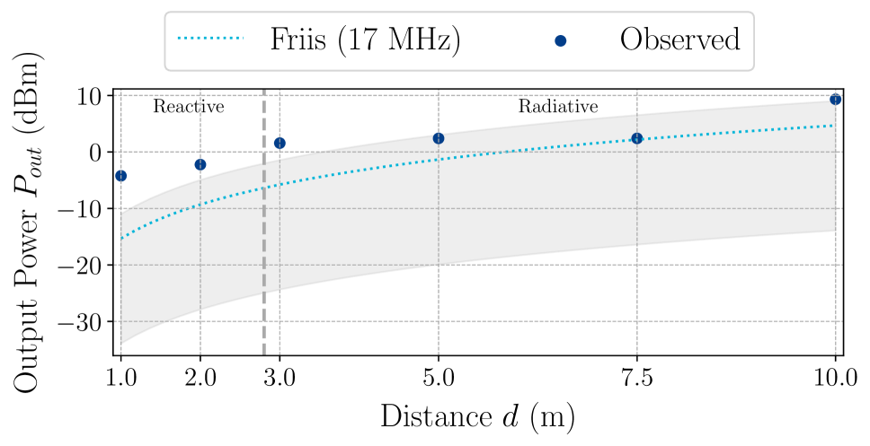
A range of mathematical methods exist for estimating received power over a wireless link. However, the majority of methods employ simplifying assumptions that may not always hold valid. The Friis path-loss equation is often used to estimate expected power levels in wireless security contexts [25]. However, the equation is only well-defined for signals in the far-field of transmission and is frequency dependent. At the comparatively low frequencies used by HPGP PLC signals, the far-field begins at least 10.7 m away from the transmitter and the difference in predicted power at a receiver changes substantially when considering the lowest or highest parts of the signal bandwidth.
Given these concerns, we investigated whether our observed results bore any similarity to those predicted by the Friis equation. Full details of the calculations are provided in Appendix A.
Figure 6 shows a comparison of the results observed in our testbed with predictions made using the Friis equation. We noted that, while the Friis estimates provide a wide range of powers, depending on the selected frequency, the estimates made using the upper end of the band were close to our observed results. This is consistent with the observations in [4], showing that the higher part of the band appeared most prone to radiating from the charging cable (and thus, we expect most prone to ingress as well). The predicted values were furthest from the observed ones in the reactive near-field region, but became closer in the radiative near-field. We tentatively suggest that the predictions would continue to be accurate beyond our furthest measured distance.
6 Real-world Testing
Following our experiments in a controlled lab environment, we also examined the effects of the Brokenwire attack in real-world scenarios. We tested the attack on a broad range of passenger cars from different manufacturers, spanning across different classes, price ranges, and charging capacities. All seven cars were equipped with a CCS charging port and followed either the ISO 15118 or the DIN 70121 standard. Table 1 gives an overview of the cars we tested. In addition, we evaluated a total of 18 charging stations from various providers. We did not exhaustively test every combination of vehicles and charging stations, but tested multiple vehicles with most chargers. In one case, we successfully tested with three vehicles charging simultaneously on identical charging stations.
| Vehicle | Class | Price ($) | Charging Capacity |
| Vehicle A | Subcompact | 50,000 | 50 kW |
| Vehicle B | Compact SUV | 85,000 | 150 kW |
| Vehicle C | Shooting Brake | 150,000 | 270 kW |
| Vehicle D | Subcompact | 20,000 | 50 kW |
| Vehicle E | Mid-size Sedan | 50,000 | 120 kW |
| Vehicle F | Mid-size SUV | 70,000 | 150 kW |
| Vehicle G | Compact | 45,000 | 125 kW |
6.1 Method
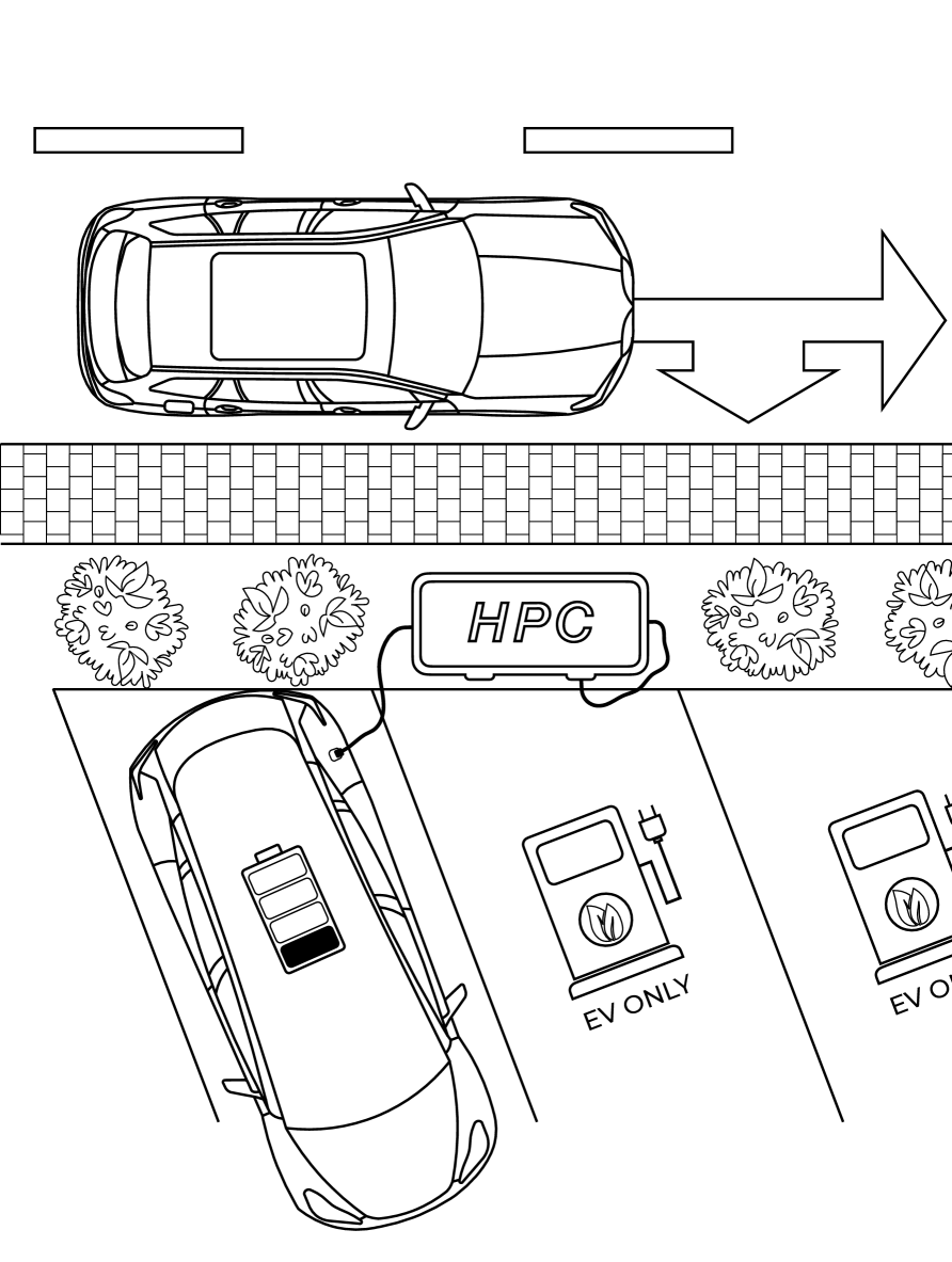
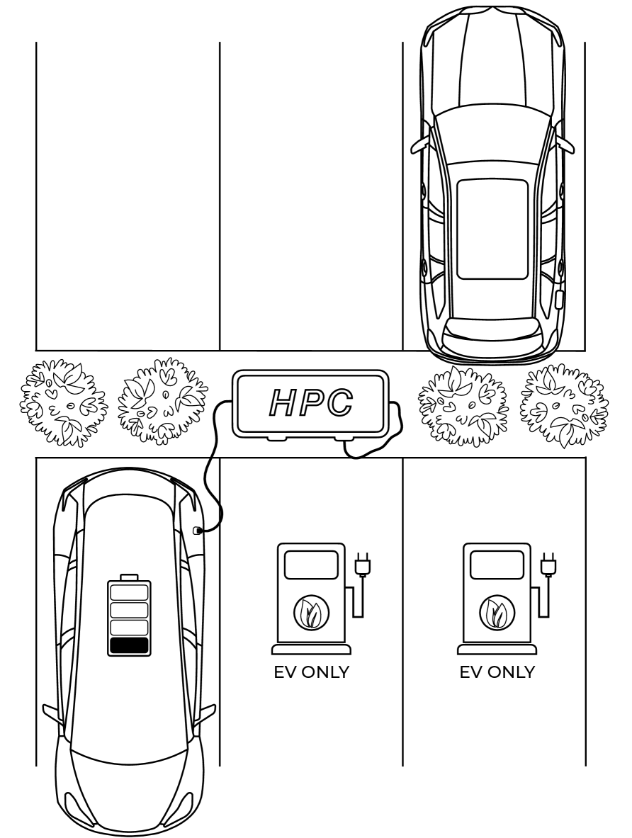
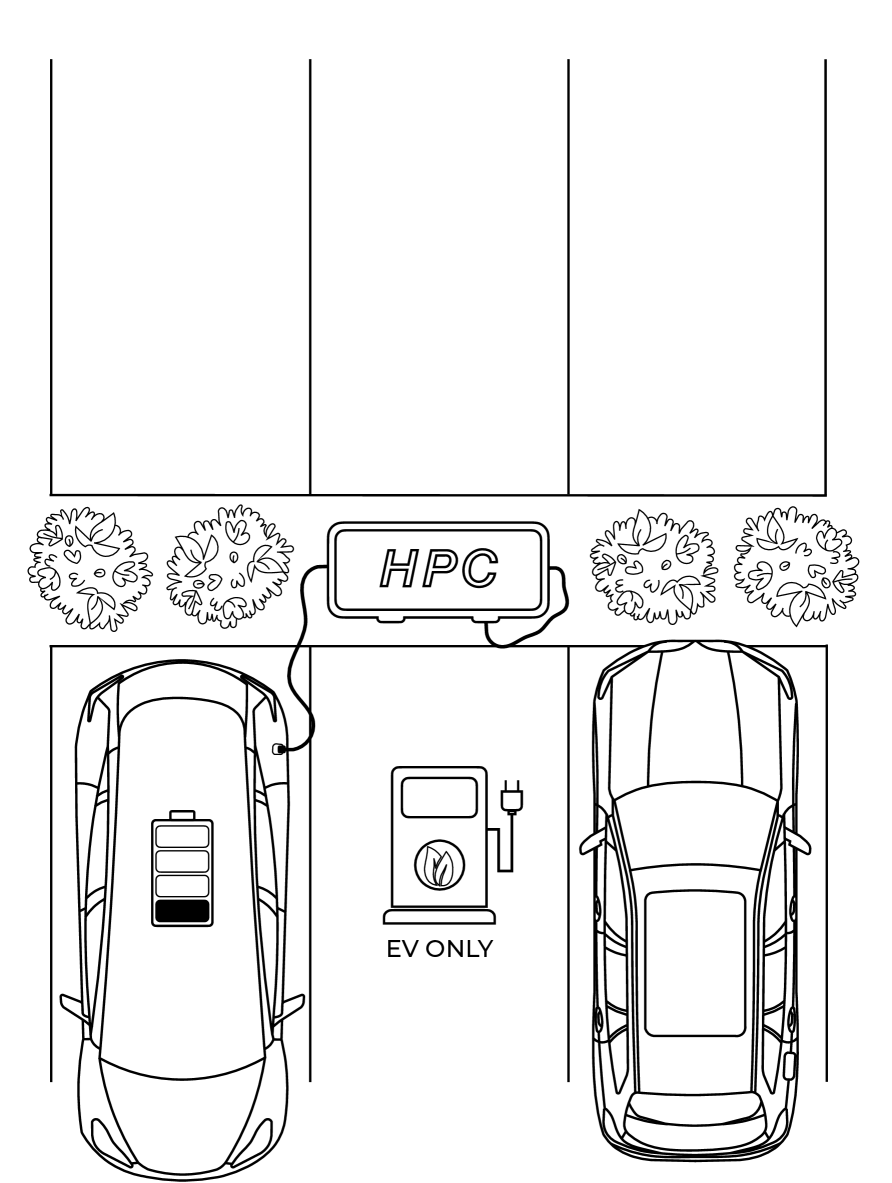
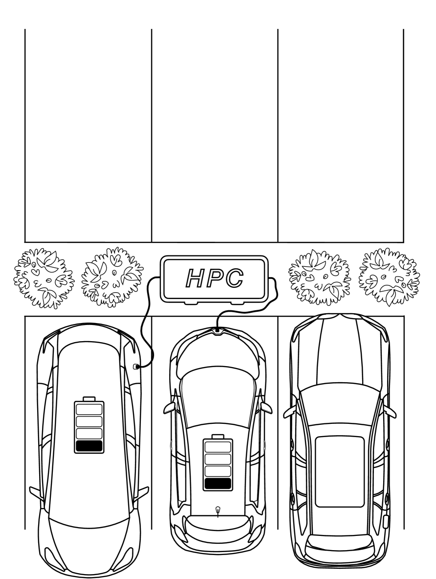
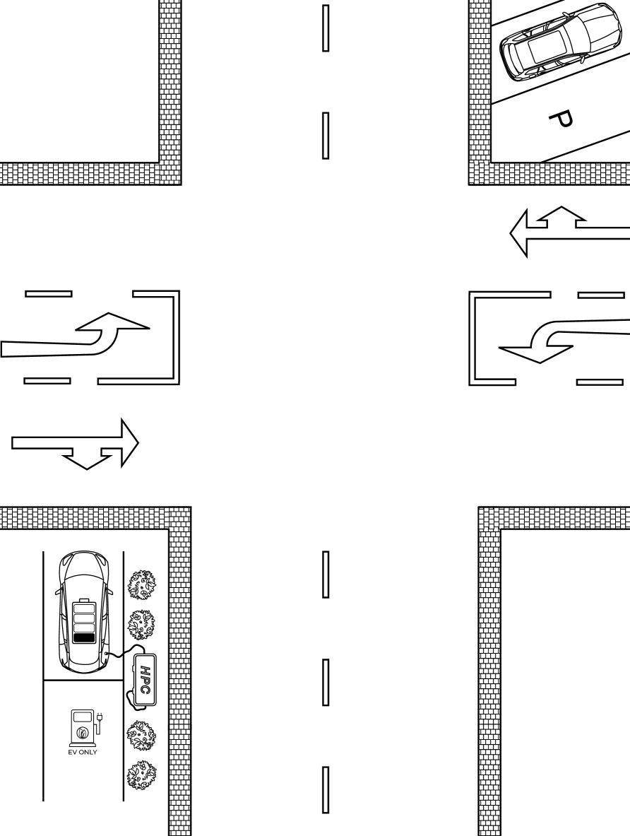
We evaluated the Brokenwire attack in various scenarios that replicate how it could be carried out in a real-world attack. Figure 7 illustrates five of the different scenarios that we examined.
Scenario 1
In this scenario, we simulated a drive-by attack, in which the adversary aims to disrupt the charging session of vehicles that are parked close to a public road. To achieve the maximum possible coverage, we mounted the antenna onto the roof of the attacking car on the site closest to the target vehicle. We then drove slowly (approx. 10 mph/15 kph) past the charging vehicle.
Scenario 2
This scenario mimicked a situation that can often be found on public car parks, for example, at supermarkets. We parked the attacking car, with the antenna coiled in the trunk, in a parking bay on the opposite side of the victim.
Scenario 3
Similar to Scenario 2, we emulated a public car park. However, this time, we parked the attacking vehicle parallel to the victim. In line with the previous scenario, we kept the antenna coiled in the trunk.
Scenario 4
Scenario 4 had the same settings as Scenario 3. However, we parked another vehicle between the attacker and the victim. This enabled us to evaluate the attack for a setting where there was no direct line-of-sight between the attacker and the victim. At the same time, it allowed us to test the attack on multiple cars at once.
Scenario 5
In Scenario 5, we simulated an attack from a distance to hide the physical presence of the adversary.
The victim was charging close to a large intersection and the adversary was located on the opposite side of the intersection.
This setting can, for example, be used to target an EV fleet at a commercial site/depot with CCTV surveillance.
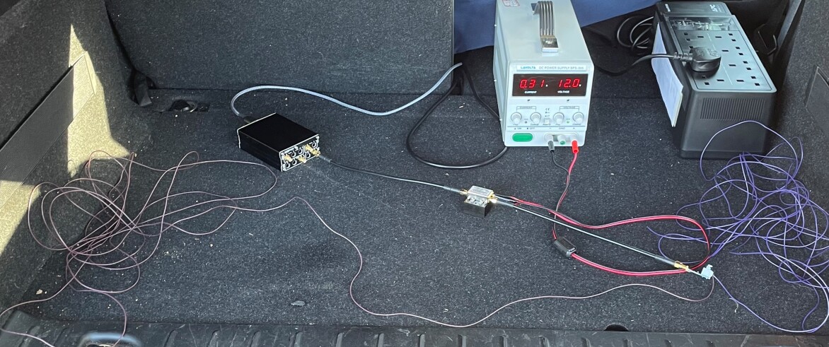
The real-world evaluation was performed with the same equipment used for the laboratory experiments.
However, the amplifier was powered from an Uninterruptible Power Supply (UPS) and a bench power source.
The setup used is depicted in Figure 8.
This research prototype cost less than $1,000 and is easily contained in the vehicle. Although we have no doubt that a suitable attack system could be assembled at far lower cost and with good portability to be carried in a rucksack.
Depending on the tested scenario, the antenna was either placed within the attacking vehicle, mounted on the bodywork, or positioned on the ground immediately next to it.
6.2 Observations
The Brokenwire attack was successful in disrupting charging in every observed case — for any combination of EV and EVSE we tested. Substantial variations were observed in effective range and power requirements in each case. However, once a suitable power level had been selected for the environment, charging sessions were terminated immediately.
Required Output Power
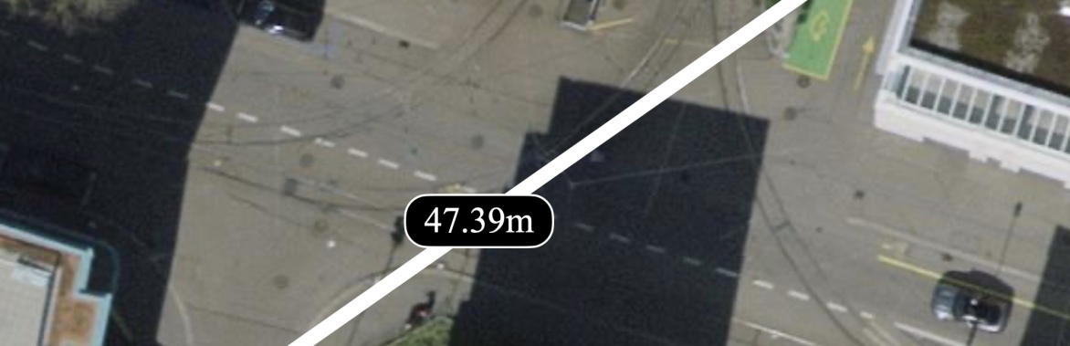
In contrast to the lab experiments, the conditions during the real-world experiments were largely uncontrolled, which led to less predictable results. In particular, we noticed that in some cases, a much higher transmission power was required to successfully terminate the charging session. For example, while we successfully disrupted the testbed from 10 m away using less than 10 mW of transmission power (see Figure 5(b)), disrupting Vehicles B and C from a distance of 10 m in a setting similar to Scenario 2 required around 600 mW. In contrast, at another charging site, we stopped vehicle D from charging using only the LimeSDR without the amplifier from 1.5 m away, which according to our measurements, corresponded to 0.3 mW of output power. At another EVSE, we replicated Scenario 5 and successfully disrupted an ongoing charging session of Vehicle D from 47 m away with just under 700 mW. The exact arrangement of this scenario is depicted in Figure 9. We believe that the large variations in the power requirements are due to several parameters that cannot be controlled by the adversary, such as electromagnetic interference from other devices, differences in signal propagation and noise generated by the charger or the vehicle itself. Nevertheless, the results from our real-world evaluation are largely in agreement with the results and observations from our laboratory experiments, showing that the attack is effective and easy to execute.
Disrupting Multiple Vehicles
Since large charging hubs, where multiple vehicles can be charged simultaneously, are becoming more common, we also evaluated the effects of the Brokenwire attack in such a setting. The arrangement was similar to Scenario 4. We tried to interrupt the charging sessions of three cars at once. We connected the vehicles to two charging stations and successfully disrupted all charging sessions at about the same time. The results also show that the attack works against occluded objects.
Antenna Alignment
We noticed that the alignment of the antenna is crucial for the effectiveness of the attack. The attack worked reliably and within moderate distance when the antenna was coiled in the closed trunk, as shown in Figure 8. However, for the same output power, the maximum possible attack range increased significantly when the antenna was stretched out. Moreover, we observed that the signal is attenuated when the trunk is closed. Moving the antenna outside increased the attack range even further. Nevertheless, our findings indicate that even a coiled antenna is adequate to conduct a successful attack. This means the antenna can easily be hidden in, for example, a backpack.
Error State
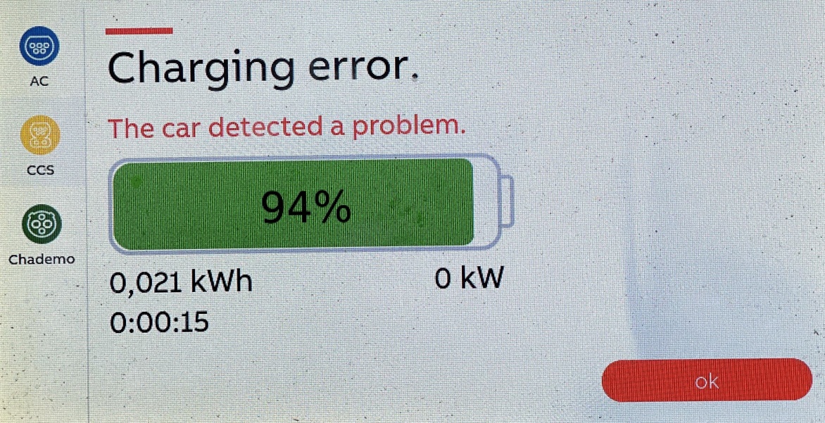
In all of our tests and independent of the vehicle and charging station, we observed that after the successful disruption of the charging communication, the car and the charger switched into an error state. An example error message displayed on one of the tested chargers is depicted in Figure 10. Even though the ISO 15118 standard provides the option of continuing the charging using the basic PWM communication [41], it appears that none of the tested vehicles implemented this feature. To continue charging, it was necessary to manually start an entirely new charging session from scratch. This means we had to unplug the charging cable from the vehicle and plug it back into the charging station, wait for a short period, plug the cable into the car again, authenticate the charging via the preferred authentication method and wait for the charging to start. While we have not observed the behavior for Plug & Charge, we are confident that the car will not automatically continue charging once the communication link is re-established. We consider this to be a safety feature since the communication is crucial for operating the equipment safely. To our surprise, one of the tested charging stations did not show an error at all. Instead, the charger stated that the charging had ended successfully.
Prevention of New Charging Sessions
In addition to disrupting ongoing charging sessions, we also tested the effects of the attack if it commences before a charging session has begun. We started broadcasting the malicious signal before the vehicle was connected to the charging station. We then tried to start a charging session as described above. In line with our expectations, the charging did not start and the EVSE displayed an error message. In contrast to the error shown in Figure 10, no state-of-charge value was displayed in this case — as the EVSE had never learned it. An adversary could use this variant of the attack to cause a denial-of-service of a certain charging hub for a longer period of time, for example, to blackmail the operator.
Liquid Cooled Cables
We tested the attack on different high-power DC charging stations with varying maximum charging capabilities ranging from 22 kW up to 320 kW. Due to the high heat dissipation during the charging process, the charging stations must comply with strict regulations to guarantee a safe operation. More specifically, for parts of the charging cable that can be grasped during the charging session, IEC 62196-1 defines a maximum temperature of C for metal and C for non-metal parts [35]. To prevent burn injuries or damage to the cable, it is crucial to operate the equipment within these specified limits. However, as charging power increases, air cooling becomes inadequate and the use of liquid cooled cables has become necessary [51]. We expected that the presence of a liquid jacket in the cable would attenuate the attack signal substantially and make the attack more difficult. However, in contrast to our expectations, we could not observe any difficulties interrupting the charging session when the charger was equipped with liquid-cooled charging cables. We argue that this is due to the coolant only running in between the current-carrying DC wires rather than wrapping around the entire cable, thus excluding the wires (CP and PE) used for the communication.
7 Impact
We consider the impact of Brokenwire to be significant. In the sections above, we have observed a variety of ways in which the attack could be successfully deployed and found it to be reliable, once suitably configured for the environment. Each category of attack within our threat model appears valid. For an attacker with a ‘single vehicle’ objective, the attack is achievable at a substantial range and almost irrespective of the target vehicle and charger. The only limitation is that the attack could affect other nearby vehicles, so it may be challenging to target only a specific vehicle at range, while leaving others unaffected. Directional transmission at these frequencies requires a large antenna arrangement, which may limit the attacker if they wish to selectively affect one vehicle from afar. However, we believe that the ability to miniaturize the equipment and conceal it still provides ample opportunity to mount this attack in a different way. Having demonstrated the disruption of multiple vehicles at once, we are confident that ‘fleet denial’ and ‘unspecific disruption’ attacks are achievable, scaled principally by the effective range of the attack. Indeed, in our multiple-vehicle test, we directly emulated the actions of an attacker attempting to render a charging site temporarily useless. We consider these as the more serious versions of the attack and so consider further details of their scalability in Section 7.2 below.
We also recall that the implications of the attack extend far beyond passenger cars. We identified a wide range of vehicles that make use of CCS charging directly, along with derivative standards based upon it. The Megawatt Charging System (MCS) and SAE J3105 follow the ISO 15118 standard and use PLC for the charging communication [11, 13]. While we have not directly tested either, we see no fundamental reason why the attack would not transfer directly to these. In both cases, these derived standards target heavy vehicles with substantial power draws and consider the needs of large, tightly-packed charging parks for fleet use. These factors would make the impact of Brokenwire particularly severe in these cases.
7.1 Transferability
There are multiple manufacturers of HPGP-compliant modems. Our testbed used the Qualcomm QCA7000, but we were not able to confirm whether any other modem implementations were in use in the vehicles we tested. As the behavior we exploit is part of the standard, we expect that any compliant implementation will be vulnerable, but consider that differences between manufacturers may affect the level of vulnerability on each.
7.2 Estimating Affected Parking Bays
Throughout our experiments in lab settings and real-world environments, we have considered the attack in terms of the distance, or effective range. However, we also demonstrated the capability for the attack to affect multiple vehicles at once and to work with occluding objects (e.g., cars, barriers) between the attacker and the victim. As such, we put our results into greater context by estimating the number of parking bays that could be affected by an attack of a given range. We stress that effective ranges are subject to variation and therefore so are counts of affected parking bays. However, we believe it is helpful to understand the scalability of the attack and that our analysis helps to illustrate other important factors, such as parking lot design.
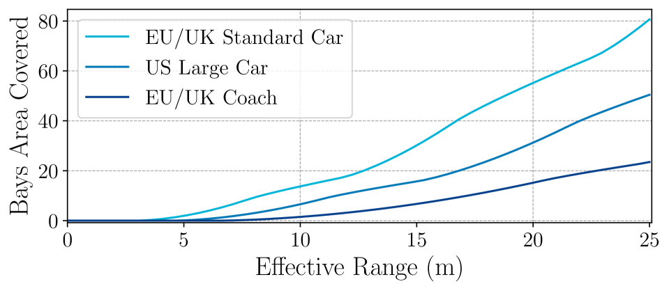
We built a simulation tool to calculate the coverage of an attack for arbitrary charging park layouts. The full details are described in Appendix B. Figure 11 shows the results of this comparison. Bays begin to be covered by the disruption signal above 4 m of range. For the tightest arrangement of parking bays (small cars, perpendicular parking, double-sided rows) an area equivalent to 80 parking bays would be covered by a 25 m range (with 64 fully overlapped). The same range would allow coverage of an area equivalent to 22 coach bays in a perpendicular arrangement (with 16 fully overlapped).
8 Ethical & Legal Considerations
Safety Measures during the Experiments
Given the nature of the infrastructure under investigation, we collaborated with several government entities for our evaluation. We further took precautions to limit any risk of unintentional effects from our testing. We selected only test sites for which no other charging parks were within a reasonable range. We only executed the attack when no other vehicles were charging and could immediately abort the experiments if the conditions became uncontrolled. Outside our closed laboratory sites, we were limited to a maximum output power of 1 W to ensure our attack signal was compliant with all national transmission regulations.
Responsible Disclosure
The findings of this paper have been disclosed to different standardization bodies, such as CharIN e.V., a non-profit association founded by car manufacturers and suppliers that leads the standardization of CCS, and Automotive Information Sharing and Analysis Center (Auto-ISAC). Although we will make our evaluation source code publicly available, we have embargoed the release of our code during the disclosure period to provide manufacturers with sufficient time to address the vulnerability while making it more difficult for a potential attacker to exploit the vulnerability.
9 Countermeasures
Parts of this section have been removed.
Preventing electromagnetic interference completely is challenging. In the following, we discuss potential countermeasures that cannot fully prevent the attack but raise the bar high enough to make the attack too resource-intensive for a would-be attacker.
9.1 Hardware Adjustments
Similar to the protection of any other electronic device, the most straightforward approach to reduce the susceptibility of the charging cable to electromagnetic waves is electromagnetic shielding. At the same time, wrapping a conductive layer around the CP and PE lines would prevent data leakage through unintentional electromagnetic emanation [4]. While adding shielding does make the attack more difficult, it does not fully prevent it. Instead, it only attenuates the injected signal with the effectiveness largely depending on the thickness of the shielding [66]. Therefore, shielding can be seen as an arms race between defender and attacker.
In addition, the extra insulation has an impact on the handling of the cable. While flexibility is important to ensure the cable can be plugged in without too much force, charging cables are already heavy, stiff, and sometimes difficult to handle. Adding an additional layer of shielding would further increase the weight and stiffness of the charging cable while also raising the price.
Finally, shielding cannot easily be retrofitted onto old cables. Therefore, it is necessary to replace the entire charging cable. Nevertheless, given a price of around $1,200 for a single charging cable, it is a time-consuming and costly task making it not economically viable.
9.2 Software Solutions
Hardware countermeasures are often challenging to deploy. In particular, the high cost of retrofitting or replacing vulnerable hardware and the limited scalability of the approach make it unattractive. Therefore, a software-based approach, which can preferably be rolled out via an over-the-air software update, would be optimal.
9.2.1 Enabling Re-Authentication
The PLC is only disrupted as long as the adversary continues to emit the malicious signal. Once the broadcasting stops, the communication link is re-established and the EV and EVSE could continue to communicate. However, as discussed in Section 6, none of the tested vehicles continued charging once the session was interrupted. Instead, the car and charger switched into an error state, forcing the user to repeat the entire authentication process. We argue that the attack would be less harmful if the vehicle would automatically re-establish the charging session once the communication link is available again. With the help of the Proximity Pilot (PP), which is part of the CCS Combo 1 and Combo 2 plug and used to detect if the charging cable has been plugged in, it would be possible to monitor if the charging cable has been unplugged. If the circuit has not been interrupted, the charger is still connected to the same vehicle, which has previously been authenticated successfully by the user, making a manual re-authentication by the user unnecessary. With the introduction of Plug & Charge, the re-establishment of the charging session is even easier. The car has all the necessary information to start charging without the need for the user to authenticate. While this countermeasure does not solve the vulnerability, it substantially reduces the impact of one-off attacks, such as the drive-by attack.
10 Related Work
Disrupting wireless communication using IEMI has been well studied [53, 6, 59, 68]. Nevertheless, simple jamming that aims to decrease the signal-to-noise ratio by emitting noise in the spectrum of the communication channel is ineffective and resource-intensive. As such, more intelligent jamming strategies that exploit design weaknesses in the targeted protocol, for example, IEEE 802.11, LTE, or 5G, have been demonstrated [12, 60, 45, 3].
It is well known that PLC is susceptible to electromagnetic interference (EMI) [56, 63, 57, 49]. At the same time, PLC tends to cause electromagnetic emanation, even so strong that it can interfere with amateur radio [49]. The work by [4] demonstrated that this also applies to the Combined Charging System. A similar attack, although wired rather than wireless, has been demonstrated in [22]. However, to the best of our knowledge, no research has been conducted that evaluates the real impact of EMI against the CCS charging communication. The authors of [5] mentioned only briefly the possibility of a denial-of-service attack against the charging communication by emitting noise in its spectrum. And the researchers in [18] focused on the electromagnetic susceptibility of the voltage and current sensors in charging stations.
11 Conclusions
In this paper, we presented Brokenwire, an attack against the Combined Charging System (CCS), the most widely used DC rapid charging standard for electric vehicles in North America and Europe. We investigated the effects of the Brokenwire attack in a controlled laboratory environment and an extensive real-world evaluation, including seven EVs and 18 charging stations. We demonstrated that the attack can be conducted with only off-the-shelf equipment and with little knowledge, making the entry barrier for an attacker low. Our results suggest that the use of PLC for charging communication is a serious design flaw that leaves millions of vehicles, some of which belong to critical infrastructure, vulnerable.
Acknowledgments
We are grateful for the support from Armasuisse S+T and EWZ (Elektrizitätswerk der Stadt Zürich). We would also like to thank Daniel and Peter Köhler for providing access to their vehicles and supporting us during some of the experiments. Sebastian was supported by the Hans-Böckler Foundation and the Engineering and Physical Sciences Research Council (EPSRC).
Availability
Our evaluation source code is available at blinded until after the embargo period. To facilitate deployment and make it easier for the community to reproduce our results, the entire project is dockerized.
References
-
[1]
Amazon.com.
Amazon’s custom electric delivery vehicles are starting to hit the
road, 2021.
https://www.aboutamazon.com/news/transportation/amazons-custom-electric-delivery-vehicles-are-starting-to-hit-the-road. -
[2]
Aqua superPower.
Aqua superPower - The Global Marine Charging Network, 2022.
https://aqua-superpower.com. - [3] Youness Arjoune and Saleh Faruque. Smart jamming attacks in 5g new radio: A review. In 2020 10th Annual Computing and Communication Workshop and Conference (CCWC), pages 1010–1015. IEEE, 2020.
- [4] Richard Baker and Ivan Martinovic. Losing the Car Keys: Wireless PHY-Layer Insecurity in EV Charging. In 28th USENIX Security Symposium (USENIX Security 19), Santa Clara, CA, 2019. USENIX Association.
- [5] Kaibin Bao, Hristo Valev, Manuela Wagner, and Hartmut Schmeck. A threat analysis of the vehicle-to-grid charging protocol ISO 15118. Computer Science-Research and Development, 33(1-2):3–12, 2018.
- [6] Emrah Bayraktaroglu, Christopher King, Xin Liu, Guevara Noubir, Rajmohan Rajaraman, and Bishal Thapa. Performance of IEEE 802.11 under jamming. Mobile Networks and Applications, 18(5):678–696, 2013.
-
[7]
BBC.co.uk.
London bus garage to become world’s largest ’trial power
station’, 2020.
https://www.bbc.co.uk/news/uk-england-london-53762711. -
[8]
BMW Group.
Bidirectional Charging Management (BCM) pilot project enters key
phase: Customer test vehicles with the ability to give back green energy.,
2021.
https://www.press.bmwgroup.com/global/article/detail/T0338036EN/bidirectional-charging-management-bcm-pilot-project-enters-key-phase:-customer-test-vehicles-with-the-ability-to-give-back-green-energy. -
[9]
BYD.
BYD Charging Solutions, 2022.
https://en.byd.com/charging-solutions. -
[10]
CharIN e.V.
Grid Integration Levels - Version 5.2, 2020.
https://www.charin.global/media/pages/technology/knowledge-base/60d37b89e2-1615552583/charin_levels__grid_integration_v5.2.pdf. -
[11]
CharIN e.V.
Megawatt Charging System (MCS), 2022.
https://www.charin.global/technology/mcs/. - [12] T Charles Clancy. Efficient ofdm denial: Pilot jamming and pilot nulling. In 2011 IEEE International Conference on Communications (ICC), pages 1–5. IEEE, 2011.
-
[13]
Hybrid EV Committee.
Electric Vehicle Power Transfer System Ussing Conductive
Automated Connection Devices, 2020.
https://doi.org/10.4271/J3105_202001. -
[14]
Jesse Crosse.
Kona to Edinburgh: 700 miles in Hyundai’s new EV for the masses,
2019.
https://www.autocar.co.uk/car-news/features/kona-edinburgh-700-miles-hyundais-new-ev-masses. -
[15]
Daimler Truck AG.
Mercedes-Benz eTruck, 2020.
https://www.mercedes-benz-trucks.com/fr_BL/brand/news/press-releases/daimler-trucks-e-mobility-group-lance-une-initiative-globale-en-faveur-de-infrastructure-de-recharge-des-camions-electriques.html. -
[16]
Daimler Trucks North America LLC.
eCascadia, 2022.
https://freightliner.com/trucks/ecascadia. - [17] HS Das, MM Rahman, S Li, and CW Tan. Electric vehicles standards, charging infrastructure, and impact on grid integration: A technological review. Renewable and Sustainable Energy Reviews, 120:109618, 2020.
- [18] Gökçen Yilmaz Dayanikli, Rees R Hatch, Ryan M Gerdes, Hongjie Wang, and Regan Zane. Electromagnetic sensor and actuator attacks on power converters for electric vehicles. In 2020 IEEE Security and Privacy Workshops (SPW), pages 98–103. IEEE, 2020.
-
[19]
devolo AG.
dLAN Green PHY eval board II, 2022.
https://www.devolo.co.uk/dlan-green-phy-eval-board-ii. -
[20]
Jameson Dow.
President Biden will make entire 645k federal vehicle fleet
electric, 2021.
https://electrek.co/2021/01/25/president-biden-will-make-entire-645k-vehicle-federal-fleet-electric. -
[21]
DPD Group.
DPD doubles EV fleet to almost 1,500 with UK’s first MAXUS e Deliver
electric van order, 2021.
https://www.dpd.co.uk/content/about_dpd/press_centre/dpd-doubles-ev-fleet-to-almost-1500-with-uks-first-maxus-edeliver-electric-van-order.jsp. - [22] Sébastien Dudek, Jean-Christophe Delaunay, and Vincent Fargues. V2g injector: Whispering to cars and charging units through the power-line. 2019.
-
[23]
EnBW.
Verkehrsreiches Autobahnkreuz bei Kamen wird Drehkreuz für
Elektromobilität im Nordwesten, 2021.
https://www.enbw.com/unternehmen/presse/groesster-enbw-schnellladepark-eroeffnet.html. -
[24]
David Ferris.
Postal Service: Here’s the price tag for 100% EVs, 2022.
https://www.eenews.net/articles/postal-service-heres-the-price-tag-for-100-evs. - [25] Harald T Friis. A note on a simple transmission formula. proc. IRE, 34(5):254–256, 1946.
-
[26]
Bryce Gaton.
The war is over: Nissan to switch from CHAdeMO to CCS in US and
Europe, 2021.
https://thedriven.io/2021/08/13/end-of-the-plug-wars-electrify-america-to-stop-installing-chademo-chargers. -
[27]
Goldhofer AG.
PHOENIX AST-2E, 2022.
https://www.goldhofer.com/en/towbarless-tractors/ast-2e-phoenix. -
[28]
Green Motion SA.
SKYCHARGER - Setting the standard of cutting-edge electric plane
charging, 2022.
https://greenmotion.ch/en/products/skycharge. -
[29]
Carrie Hampel.
Huge order for Lion Electric trucks from Amazon, 2021.
https://www.electrive.com/2021/01/11/huge-order-for-lion-electric-trucks-from-amazon. -
[30]
Carrie Hampel.
NHS develops electric ambulances with Ford, 2021.
https://www.electrive.com/2021/08/09/nhs-procures-fleet-of-electric-ambulances. -
[31]
Roger Harrabin.
Ban on new petrol and diesel cars in UK from 2030 under PM’s green
plan, 2020.
https://www.bbc.co.uk/news/science-environment-54981425. -
[32]
HomePlug Powerline Alliance.
Homeplug Green PHY Specification.
2013.
https://web.archive.org/web/20180825120357/https://www.homeplug.org/media/filer_public/74/40/7440ccd5-8c66-49ed-a2ce-5ef661932c27/homeplug_gp_specification_v111_final_public.pdf. -
[33]
Honda Motor Europe Ltd.
Honda and V2X Suisse Consortium to advance Vehicle-to-Grid Charging
Technology in Switzerland, 2022.
https://hondanews.eu/eu/en/cars/media/pressreleases/362145/honda-and-v2x-suisse-consortium-to-advance-vehicle-to-grid-charging-technology-in-switzerland. - [34] IEC 61581. Electric vehicle conductive charging system. IEC, Genf, Schweiz, 2017.
- [35] IEC 62196-1. Plugs, socket-outlets, vehicle connectors and vehicle inlets. Conductive charging of electric vehicles. General requirements. IEC, Genf, Schweiz, 2014.
-
[36]
Grandview Research Inc.
Electric Vehicle Charging Infrastructure Market Size, Share &
Trends Analysis Report By Charger Type (Slow, Fast), By Connector (CHAdeMO,
CCS), By Application (Commercial, Residential), And Segment Forecasts, 2021 -
2028, 2021.
https://www.grandviewresearch.com/industry-analysis/electric-vehicle-charger-and-charging-station-market. -
[37]
Independent.co.uk.
Germany pushes to ban petrol-fuelled cars within next 20 years,
2016.
https://www.independent.co.uk/news/world/europe/germany-petrol-car-ban-no-combustion-diesel-vehicles-2030-a7354281.html. -
[38]
Roland Irle.
Global EV Sales for 2021 H1, 2022.
https://www.ev-volumes.com. - [39] ISO 15118-1. Road vehicles – Vehicle to grid communication interface – Part 1: General information and use-case definition. ISO, Genf, Schweiz, 2014.
- [40] ISO 15118-2. Road vehicles – Vehicle to grid communication interface – Network and application protocol requirements. ISO, Genf, Schweiz, 2014.
- [41] ISO 15118-3. Road vehicles - Vehicle to grid communication interface – Part 3: Physical and data link layer requirements. ISO, Genf, Schweiz, 2015.
-
[42]
Kevin Joshua.
List of Countries Banning Internal Combustion Engines in the Near
Future, 2021.
https://www.ecomparemo.com/info/list-of-countries-banning-internal-combustion-engines-in-the-near-future. -
[43]
Mark Kane.
Incredible Electric Ferry Fast Charges Using 26 Plugs
Simultaneously, But Why?, 2021.
https://insideevs.com/news/466633/electric-ferry-26-plugs-dc-fast-charging. - [44] John Kraus. Antennas for all applications. McGraw-Hill, New York, 2002.
- [45] Matthew J La Pan, T Charles Clancy, and Robert W McGwier. Physical layer orthogonal frequency-division multiplexing acquisition and timing synchronization security. Wireless Communications and Mobile Computing, 16(2):177–191, 2016.
-
[46]
Fred Lambert.
Kia unveils 2020 Soul EV with 201HP, 64kWh, 200+ mile battery and
100kW CCS charging, 2018.
https://electrek.co/2018/11/29/kia-2020-soul-ev-battery-pack-range. -
[47]
Fred Lambert.
Tesla confirms Model 3 is getting a CCS plug in Europe, adapter
coming for Model S and Model X, 2018.
https://electrek.co/2018/11/14/tesla-model-3-ccs-2-plug-europe-adapter-model-s-model-x. -
[48]
Fred Lambert.
Tesla unveils updated Model S with new headlights, taillights, and
CCS charge ports, 2022.
https://electrek.co/2022/01/11/tesla-unveils-updated-model-s-new-headlights-taillights-ccs-charge-ports. - [49] Lutz Lampe, Andrea M. Tonello, and Theo G. Swart. Power Line Communications: Principles, Standards and Applications from Multimedia to Smart Grid. Wiley Publishing, 2nd edition, 2016.
-
[50]
John Reid & Sons Ltd.
Car Parking Bays, 2022.
https://multi-storey-car-parks.com/car_parking_bays.html. - [51] Christopher J Michelbacher, Shabbir Ahmed, Ira Bloom, Andrew Burnham, Barney Carlson, Fernando Dias, Eric J Dufek, Andrew N Jansen, Matthew Keyser, David Howell, et al. Enabling fast charging: A technology gap assessment. Technical report, Idaho National Lab.(INL), Idaho Falls, ID (United States), 2017.
- [52] Mine Smart Ferry. Mine Smart Ferry - Innovation, 2022. https://minesmartferry.com/innovation.
- [53] Ryan H Mitch, Ryan C Dougherty, Mark L Psiaki, Steven P Powell, and Brady W O’Hanlon. Signal characteristics of civil gps jammers. In Radionavigation Laboratory Conference Proceedings, 2011.
-
[54]
Charles Morris.
The war is over: Nissan to switch from CHAdeMO to CCS in US and
Europe, 2020.
https://chargedevs.com/newswire/the-war-is-over-nissan-to-switch-from-chademo-to-ccs-in-us-and-europe. - [55] Francis Mwasilu, Jackson John Justo, Eun-Kyung Kim, Ton Duc Do, and Jin-Woo Jung. Electric vehicles and smart grid interaction: A review on vehicle to grid and renewable energy sources integration. Renewable and sustainable energy reviews, 34:501–516, 2014.
- [56] Arash Nateghi, Martin Schaarschmidt, Sven Fisahn, and Heyno Garbe. Susceptibility of Power Line Communication (PLC) Channel to DS, AM and Jamming Intentional Electromagnetic Interferences. In 2021 Asia-Pacific International Symposium on Electromagnetic Compatibility (APEMC), pages 1–4. IEEE, 2021.
- [57] Arash Nateghi, Martin Schaarschmidt, Sven Fisahn, and Heyno Garbe. Susceptibility of Power Line Communication (PLC) Channel to DS, AM and Jamming Intentional Electromagnetic Interferences. In 2021 Asia-Pacific International Symposium on Electromagnetic Compatibility (APEMC), pages 1–4, 2021.
-
[58]
The Institution of Structural Engineers.
Design recommendations for multi-storey and underground car parks,
2002.
https://masseguridadvial.com/FILES/Underground_Carparks_EN.pdf. - [59] Richard A. Poisel. Modern Communications Jamming Principles and Techniques. Artech House, Inc., Norwood, MA, USA, 2nd edition, 2011.
- [60] Hanif Rahbari, Marwan Krunz, and Loukas Lazos. Swift jamming attack on frequency offset estimation: The Achilles’ heel of OFDM systems. IEEE Transactions on Mobile Computing, 15(5):1264–1278, 2015.
-
[61]
Royal Mail Group Limited.
Royal Mail switches on all-electric company car schemes, 2022.
https://www.royalmailgroup.com/en/press-centre/press-releases/royal-mail-group/royal-mail-switches-on-all-electric-company-car-schemes. -
[62]
Siemens AG.
Siemens technology becoming part of state-of-the-art bus depot in
Hamburg, 2020.
https://press.siemens.com/global/en/pressrelease/siemens-technology-becoming-part-state-art-bus-depot-hamburg. - [63] Manuel Martin Soriano and Andrew W Mitchell. Feasibility of powerline communications (PLC) on future spacecraft EMI/EMC test results on cots PLC technology. In 2017 IEEE International Symposium on Electromagnetic Compatibility & Signal/Power Integrity (EMCSI), pages 38–43. IEEE, 2017.
-
[64]
Matthias Spöttle, Maarten Staats, Korinna Jörling, Matthias Schimmel, John
Gartner, Lisa Jerram, William Drier, and Logan Grizzel.
Research for TRAN Committee – Charging infrastructure for electric
road vehicles, 2018.
https://www.europarl.europa.eu/RegData/etudes/STUD/2018/617470/IPOL_STU(2018)617470_EN.pdf. -
[65]
Victoria Tomlinson.
UPS invests in Arrival and orders 10,000 Generation 2 Electric
Vehicles, 2020.
https://arrival.com/uk/en/news/ups-invests-in-arrival-and-orders-10000-generation-2-electric-vehicles. - [66] Xingcun Colin Tong. Advanced materials and design for electromagnetic interference shielding. CRC press, 2016.
-
[67]
Volkswagen AG.
Convenient, networked and sustainable: new solutions for charging
electric Volkswagen models, 2022.
https://www.volkswagen-newsroom.com/en/press-releases/convenient-networked-and-sustainable-new-solutions-for-charging-electric-volkswagen-models-7695. - [68] Wenyuan Xu, Wade Trappe, Yanyong Zhang, and Timothy Wood. The feasibility of launching and detecting jamming attacks in wireless networks. In Proceedings of the 6th ACM international symposium on Mobile ad hoc networking and computing, pages 46–57, 2005.
-
[69]
Jim Zyren.
EV Combined Charging System Featuring HomePlug Green PHY, 2015.
https://www.qualcomm.com/sites/ember/files/uploads/ev_combined_charging_qualcommautotechconf_april_2015.pdf.
Appendix A Comparison to Friis Equation
This section has been removed.
Appendix B Parking Bay Coverage Simulation
In order to help assess the scalability of Brokenwire, we created a simulation tool to help estimate how the effective range of an attack covers bays in parking lots.
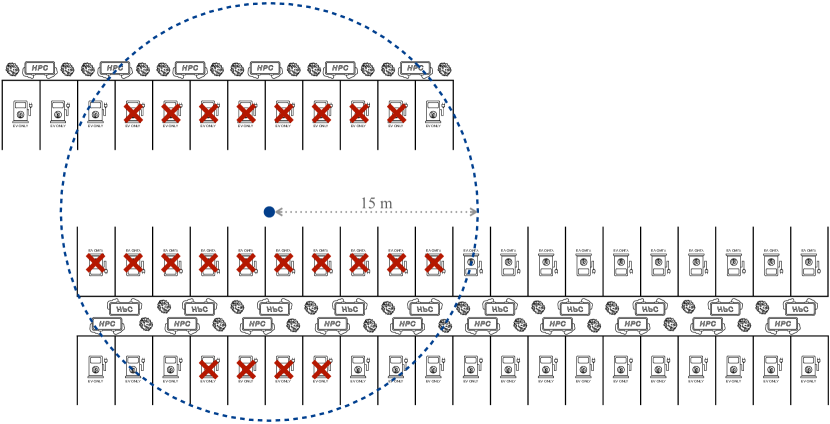
In Figure 12, we illustrate the layout of the charging hub pictured in Figure 1 and show how a ‘drive-by’ attack with an effective range of 15 m could be expected to affect approximately 22 vehicles at once.
However, the design of parking lots varies substantially, not only in terms of regulations on sizing and angle, but also in layout, which is subject to site constraints and design choices by the land developers. In Figure 12 there is a central, double-sided row (i.e., bays on both sides of a sidewalk) and another single-sided row, offset in the top-left.
Given this variation, our simulation accepts as input an arbitrary description of the layout of a parking lot, along with an attacker location and effective range. The simulation then estimates the number of parking bays that could be affected by an attack of that size. Bays can be defined with any size, shape and orientation, allowing the simulation to consider bays suitable for any type of vehicle. An attacker can be situated at any point within the layout — including outside the parking lot. They are modeled as a point-source with a uniform, circular radiation pattern. The simulation computes the total area of parking bays covered by an attack of a given range. Although we have shown effectiveness of the attack between floors, we implement only the 2-dimensional case here. We make the simulation tool available as part of our open source code.
For the analysis in the main text, we consider an example parking lot arrangement. This does not follow a specific real-world case, as in Figure 12, but a generally common design. While there are site-specific variations, parking bays are typically arranged in regular patterns, broken only by access roads and site boundaries. We use a double-sided arrangement in repeated rows, with chargers between rows, perpendicular parking and a range of bay sizes and spacings from regulations around the world [58, 50]. EU/UK ‘normal’ bays are 2.4 m 4.8 m with access road width of 6 m. US ‘large’ bays are 3.2 m 6.5m with 9.2 m roads. EU/UK coach bays are 3.5 m 14 m with 13 m roads.
The parking lot is scaled to be sufficiently large for any effective range selected. Our selected layout represents the most dense arrangement used in real parking lots — such as in Figure 12. As such our results give an upper bound on the scale of the attack, yet still a realistic one.
We selected an attacker position that maximizes the coverage of parking bays: centrally-positioned in the parking lot on an access road. We simulate for distances up to 25 m, noting that while we achieved success at nearly double this range, charging parks with more than 50 fast-charging bays are all but non-existent at time of writing.