Canceling and inverting normal and anomalous group-velocity dispersion using space-time wave packets
Abstract
Angular dispersion can counterbalance normal group-velocity dispersion (GVD) that increases the wave-vector length in a dispersive medium. By tilting the wave vector, angular dispersion reduces the axial wave number in this case to match the pre-GVD value. By the same token, however, angular dispersion fails to counterbalance anomalous GVD, which in contrast reduces the wave-vector length. Consequently, GVD-cancellation via angular dispersion has not been demonstrated to date in the anomalous dispersion regime. We synthesize here structured femtosecond pulsed beams known as ‘space-time’ wave packets designed to realize dispersion-cancellation symmetrically in either the normal- or anomalous-GVD regimes by virtue of non-differentiable angular dispersion inculcated into the pulsed field. Furthermore, we also verify GVD-inversion: reversing the GVD sign experienced by the field with respect to that dictated by the chromatic dispersion of the medium itself.
I Introduction
Chromatic dispersion resulting from the wavelength-dependence of the refractive index is an inescapable feature of optical materials, which leads to pulse broadening and distortion [1, 2]. One may combat its impact via dispersion compensation or dispersion cancellation. In the former, dispersive broadening and the associated chirp are compensated after (or pre-compensated before) passage through the medium, which is key to the success of chirped pulsed amplification (CPA) [3], for example. Normal group-velocity dispersion (GVD) can be compensated by a pair of gratings or prisms [4], anomalous GVD by a Martinez stretcher [5], and almost arbitrary dispersion by a pulse shaper or other techniques [6, 7, 8, 9, 10, 11]. In all these cases, it is the group delay dispersion (GDD) that is being neutralized. More challenging, however, is to neutralize dispersion during passage through a dispersive medium, so that the pulse travels invariantly, which we refer to as dispersion cancellation. Such a capability is crucial, for instance, in enabling efficient nonlinear interactions in long crystals. Angular dispersion [12], whereby each frequency in the pulse is directed at a prescribed angle, has been successfully utilized for this purpose [13]. The resulting field structure after inculcating angular dispersion is typically known as a tilted pulse front (TPF) [14]. To date, however, angular dispersion has been used for dispersion cancellation in only the normal-GVD regime. There have been no reports of dispersion-cancellation in the anomalous-GVD regime, and well-established theoretical considerations suggest the impossibility of such a goal [15]. Indeed, there is strong a priori conceptual support for such a claim. Because normal GVD increases the wave-vector length in the dispersive medium by a frequency-dependent amount, Changing the wave-vector angle for each frequency can reduce its axial component to the pre-GVD value. Anomalous GVD, on the other hand, reduces the wave-vector length, and no angular tilt can compensate for such a reduction. Consequently, cancelling anomalous GVD has not been reported to date.
Nevertheless, pulsed beams or wave packets that are propagation invariant (diffraction-free and dispersion-free) in dispersive media by virtue of their spatio-temporal field structure have been known to exist theoretically [16, 17, 18, 19, 20, 21] in presence of normal and [22] anomalous [23] GVD. These sought-after dispersion-free structured fields have not been observed to date in linear dispersive media, although there is evidence for their presence in nonlinear interactions [24, 25, 26, 27]. Such spatiotemporally structured fields have been recently studied systematically in free space and non-dispersive dielectrics under the rubric of ‘space-time’ (ST) wave packets [28, 29, 30, 31, 32, 33, 34]. These propagation-invariant wave packets feature a unique set of characteristics including tunable group velocities in absence of chromatic dispersion [35, 36, 37, 38], self-healing [39], anomalous refraction [40, 41, 42, 43, 44], and novel ST Talbot effects [45]. The central characteristics of ST wave packets in free space are now well-understood [46, 34], and potential applications are being evaluated in optical communications [47, 48] and device physics [49, 50, 51, 52, 53, 54, 55].
In contrast to TPFs, the angular dispersion undergirding ST wave packets is ‘non-differentiable’: the derivative of the propagation angle is not defined at one wavelength [56, 57, 58]. Such angular dispersion can be produced by a recently developed pulsed-beam shaper that serves as a universal angular-dispersion synthesizer in one dimension [59]. We have recently shown that non-differentiable angular dispersion is the crucial ingredient for tuning the group velocity of a ST wave packet and introducing an arbitrary dispersion profile in free space [60, 57]. This suggests the prospect for dispersion-cancellation in presence of either normal- or anomalous-GVD.
Here, we verify the propagation invariance of ST wave packets symmetrically in both the normal- and anomalous-GVD regimes, the latter for the first time to the best of our knowledge. We identify the spatio-temporal spectral structures needed for achieving GVD-cancellation. The crucial step is to first change the ST wave-packet group velocity via non-differentiable angular dispersion, which opens up a space for subsequent decrease or increase in the axial wave vector relative to the dispersion-free configuration. We sculpt the spatio-temporal spectrum of -fs (-nm-bandwidth) pulses to produce ST wave packets that are propagation invariant at a wavelength of m in ZnSe as a representative normal-GVD medium, and chirped Bragg mirrors that produce anomalous GVD. Uniquely, the GVD in the medium is cancelled while maintaining independent control over the group velocity of the ST wave packet (in both the subluminal and superluminal regimes). Furthermore, not only is propagation invariance achieved in dispersive media, but dispersion inversion is also verified: the sign of GVD experienced by the wave packet in the medium is reversed. We thus produce wave packets that undergo normal GVD in an anomalously dispersive medium, and vice versa. We expect these results to be particularly useful in tailoring multi-wavelength nonlinear optical interactions in long crystals.
II The challenge of canceling anomalous GVD via angular dispersion
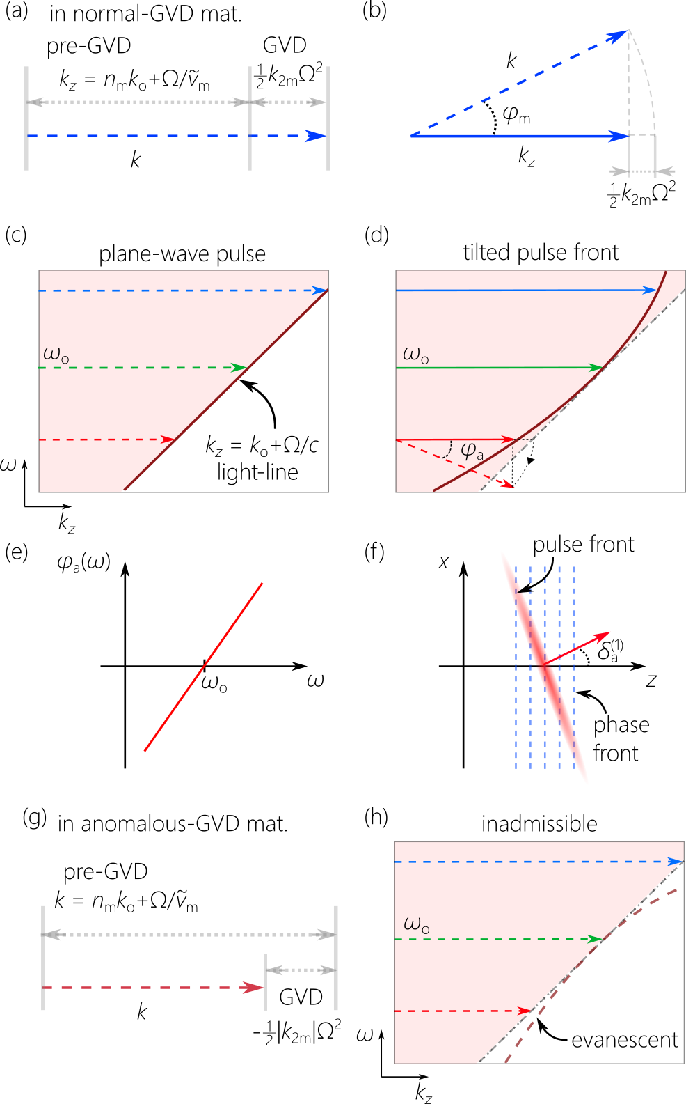
Angular dispersion, whereby each frequency in a pulsed field travels at a different angle [12], produces anomalous GVD in free space [15, 4, 61], which can help cancel normal GVD [13, 16]. In fact, it is commonly understood that angular dispersion cannot produce normal GVD in free space [15], and thus does not provide the possibility of cancelling anomalous GVD. The illustration in Fig. 1 elucidates the origin of this asymmetry between realizing normal and anomalous GVD via conventional angular dispersion.
Consider a plane-wave pulse traveling in a dispersive medium of refractive index , and expand the wave number around a frequency , ; here , , is the speed of light in vacuum, , is the group velocity and the group index, and is the GVD coefficient [1]. Throughout, we use the subscript ‘m’ to denote quantities in the dispersive medium, and the subscript ‘a’ for the corresponding quantities in free space. It is clear that normal GVD increases the wave-vector length by a frequency-dependent amount [Fig. 1(a)], which can be counterbalanced by tilting the wave vector by an angle to reduce the axial component of the wave vector in the medium to the pre-GVD value [Fig. 1(b)]. To realize this condition in the small-angle limit starting with a plane-wave pulse in free space [Fig. 1(c)], we tilt the wave vector associated with by an angle [Fig. 1(d,e)], where is the tilt angle of the pulse front (the plane of constant amplitude) with respect to the phase front (the plane of constant phase) [Fig. 1(f)]. Such a field structure is known as a TPF [14], which in general experiences anomalous GVD in free space [16]. Once coupled to a medium in its normal-GVD regime, the TPF propagates dispersion-free if (Appendix).
The challenge of cancelling anomalous GVD is now clear. Anomalous GVD reduces in the medium by [Fig. 1(g)], and no angular tilt can increase to the pre-GVD value. As shown in Fig. 1(h), the dispersion curve for normal GVD in free space lies below the light-line, corresponding to an evanescent field. Although this appears to be an insurmountable obstacle, we show here that it is resolved by ST wave packets endowed with non-differentiable angular dispersion.
III Theory of propagation-invariant space-time wave packets in dispersive media
III.1 Symmetrized anomalous and normal GVD in free space via angular dispersion
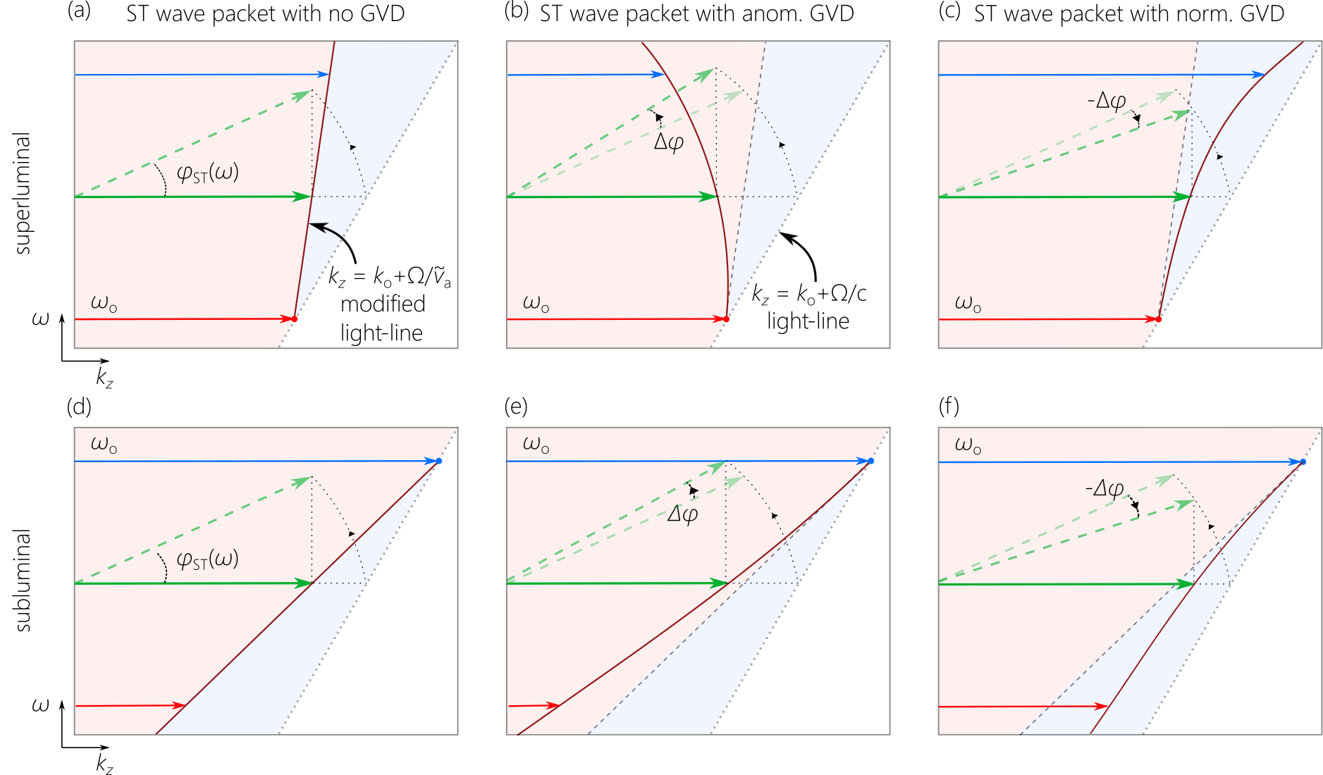
The key to introducing anomalous or normal GVD symmetrically into a pulsed field is to first change the group velocity along the propagation axis, which is given by: ; where and [16]. For on-axis propagation , for any finite value of . However, setting , which is not differentiable at , yields a propagation-invariant ST wave packet with a group velocity and group index , where is a frequency-independent constant [57, 58]. For a superluminal ST wave packet , is the minimum frequency in the spectrum [Fig. 2(a)]; and for the subluminal counterpart , is the maximum [Fig. 2(d)]. The axial wave numbers are now limited by the modified light-line rather than the free-space light-line [Fig. 2(a,d)]. Because is linear in , the ST wave packet is dispersion-free.
It can now be appreciated how anomalous or normal GVD are induced in free space. Anomalous GVD requires reducing by further increasing the angular tilt, , with respect to the GVD-free configuration [Fig. 2(b,e)]. This regime is also accessible via conventional TPFs. In contrast, normal GVD requires increasing with respect to the GVD-free configuration by reducing the angular tilt [Fig. 2(c,f)]. Because of the space that opened up above the free-space light-line but below the modified light-line , we can increase without the field becoming evanescent. This regime is inaccessible to TPFs [Fig. 1(h)] or other structured pulsed fields, and requires non-differentiable angular dispersion for its realization.
III.2 Coupling from free space to a dispersive medium
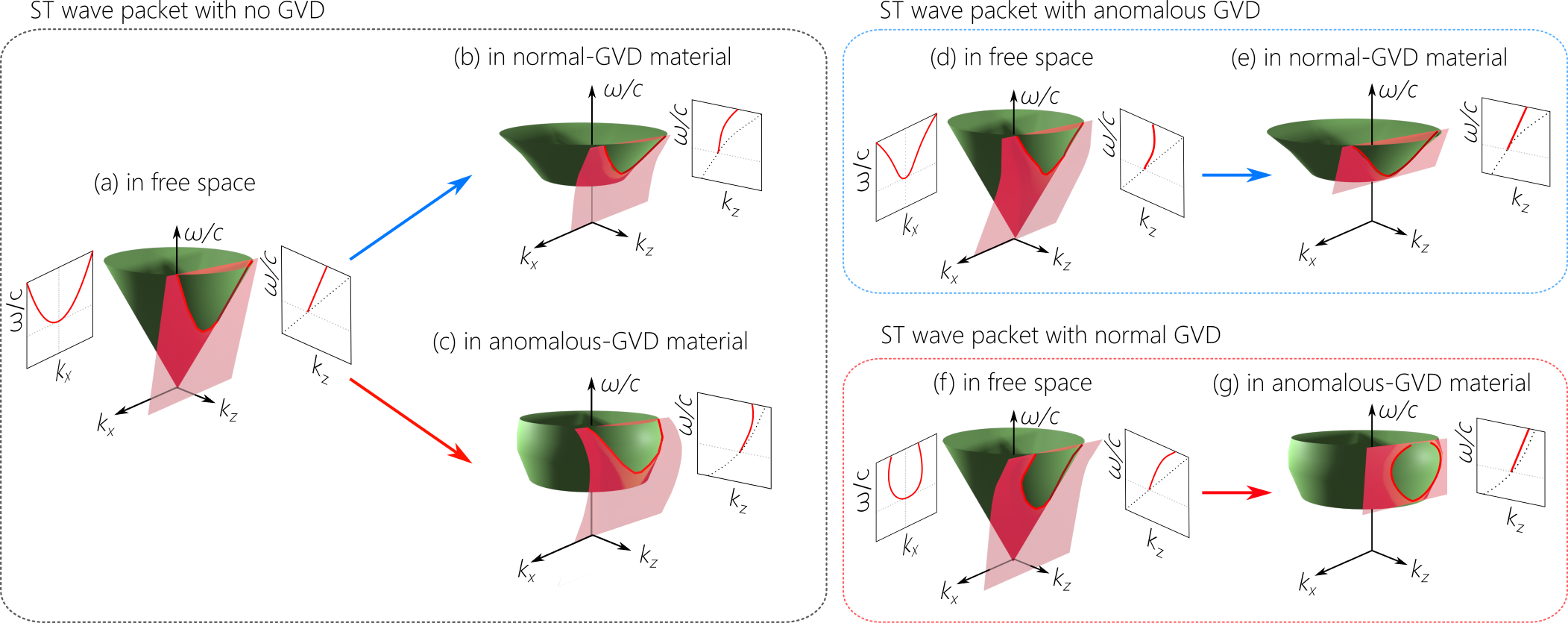
To analyze quantitatively the scenario illustrated in Fig. 2, the representation of the spectral support domain of pulsed fields on the surface of the light-cone is a useful guide [62, 34]. In free space, the light-cone is , where is the transverse wave number or spatial frequency (we hold the field uniform along for simplicity). The spectral support domain for a propagation-invariant ST wave packet traveling at a group velocity is the intersection of the light-cone with a plane that is parallel to the -axis and makes an angle (the spectral tilt angle) with the -axis [63, 36, 64], where [Fig. 3(a)]. The spectral projection onto the -plane is a straight line, and onto the -plane is a conic section that can be approximated by a parabola in the vicinity of in the paraxial regime [37, 64].
In presence of GVD due to chromatic dispersion, the dispersion relationship corresponds to a modified light-cone [Fig. 3(b,c)]. At normal incidence on a planar interface, and are invariant, so the -projection is the same in free space and the dispersive medium:
| (1) |
However, the -projection changes because the light-cone structure has been modified. The ST wave packet that was propagation-invariant in free space now experiences GVD in the dispersive medium. We expand the axial wave number in the medium as , where is the group velocity of the ST wave packet in the medium (which need not be equal to ), and is the effective GVD coefficient (which can differ from the GVD coefficient in the medium).
By equating the first-order terms in Eq. 1, we obtain:
| (2) |
which can be recognized as the law of refraction for a ST wave packet in a dispersive medium derived in [65, 66] that governs the change in group velocity from in free space to in the medium. Indeed, the quantity is a refractive invariant for ST wave packets at normal incidence on planar interfaces between dispersive media, which we have called the ‘spectral curvature’ because it is related to the curvature of the parabolic -projection in the vicinity of . This relationship indicates that a subluminal ST wave packet in free space remains subluminal in the medium , and similarly for superluminal wave packets.
Equating the second-order terms in Eq. 1 yields a relationship between the GVD coefficient of the medium and the effective GVD coefficient experienced by the wave packet :
| (3) |
From this we conclude that the ST wave packet experiences the normal or anomalous GVD intrinsic to the medium itself [Fig. 3(b,c)] except for an offset term:
| (4) |
In most cases where the deviation from the luminal limit is small ( and ), can be ignored, and we have .
III.3 Achieving dispersion-free propagation in presence of GVD
Dispersion-free propagation in the dispersive medium is achieved by modifying the structure of the ST wave packet in free space to introduce GVD of opposite sign to that of the medium: cancelling normal GVD necessitates endowing the ST wave packet in free space with anomalous GVD [Fig. 3(d,e)], and vice versa [Fig. 3(f,g)]. In free space, the -projection is no longer a straight line, but rather takes the form , where is the GVD coefficient introduced into the ST wave packet. The spectral support domain on the free-space light-cone is its intersection with a planar curved surface that is parallel to the -axis:
| (5) |
The change in the light-cone structure in the medium in conjunction with the invariance of the -projection can yield a -projection in the medium that is a straight line. In other words, the curved -projection in free space has been ‘straightened out’ in the medium such that , thus signifying dispersion-free propagation in the medium:
| (6) |
Equating the -terms in Eq. 5 and Eq. 6 yields as in Eq. 2), whereas equating the -terms yields:
| (7) |
That is, dispersion cancellation requires that the dispersion coefficient introduced in free space must have the opposite sign to that of the medium , and to be weighted by the refractive index . This result is similar to that for a TPF (Appendix) except that the GVD to be cancelled can be either normal or anomalous (in addition to the minor offset term ).
IV Experiment
IV.1 Spatio-temporal spectral synthesis
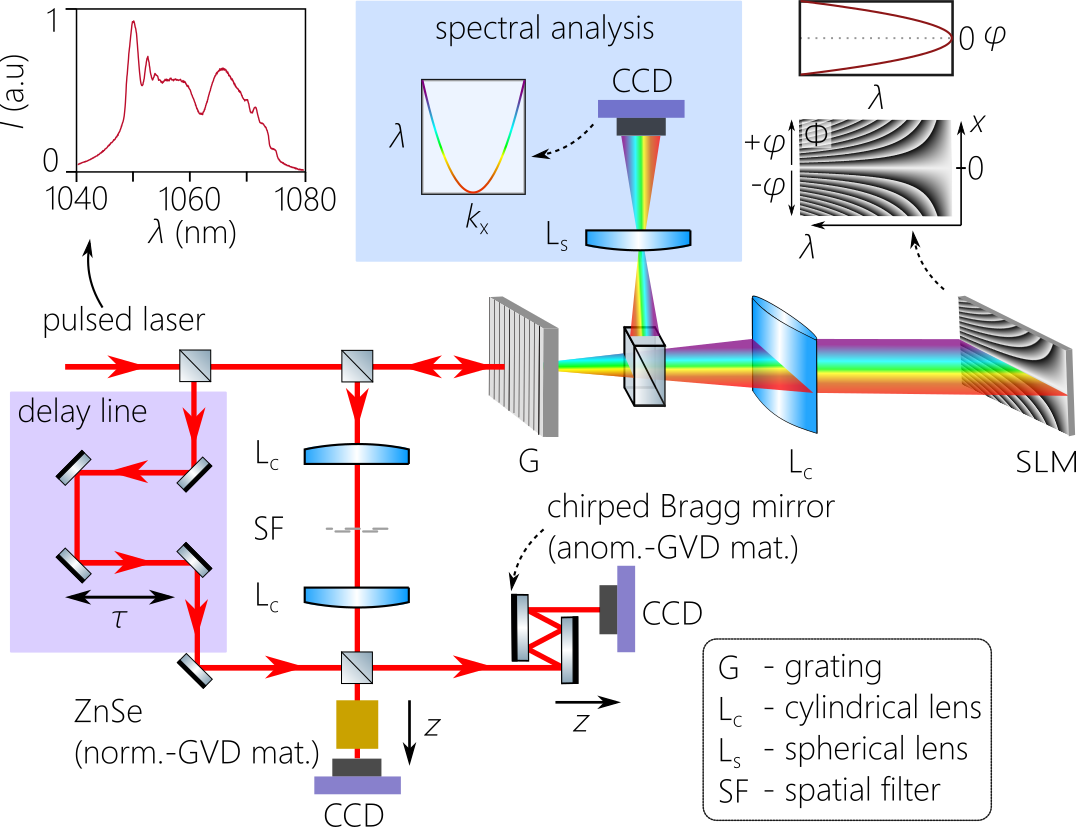
To synthesize dispersive ST wave packets in free space, we make use of the universal angular-dispersion synthesizer described in [59] and depicted in Fig. 4. We start with plane-wave femtosecond pulses of width fs and bandwidth nm at a central wavelength of nm (Spark Lasers; Alcor). The pulses are spectrally resolved via a diffraction grating (1200 lines/mm) followed by a collimating cylindrical lens of focal length mm. At the focal plane of the lens we place a reflective, phase-only spatial light modulator (SLM; Meadowlark, E19X12) that imparts a 2D phase distribution to the impinging spectrally resolved wave front. Each wavelength occupies a column on the SLM, along which we impose the phase , where is the deflection angle for with respect to the -axis. An example of the phase pattern is depicted in Fig. 4, inset. The upper half of each SLM column deflects the wavelength at an angle , while the lower half deflects it at . This yields a symmetric spatio-temporal angular spectrum [Fig. 4, inset], and produces a X-shaped wave-packet profile, whereas that for TPFs [Fig. 1(f)] comprises one branch of the X-shaped profile. The wave front retro-reflected from the SLM returns to the grating where the ST wave packet is formed, and the dispersive sample is placed in its path.
IV.2 Dispersive samples
The normal-GVD medium is ZnSe (Thorlabs; WG71050) formed of multiple 1-inch-diameter discs of thickness 5 mm each, stacked to a maximum thickness of 30 mm. Using the Sellmeier equation for ZnSe, ( in units of m) [67], we obtain at nm an index , group index , and GVD parameter fs2/mm. It is useful to exploit the dimensionless GVD parameter .
The anomalous-GVD sample comprises a pair of chirped Bragg mirrors (Edmund Optics, 12-335) that generate -1000 fs2 group delay dispersion (GDD) per reflection. By changing the distance separating the two mirrors, we can increase the number of reflections for a given propagation distance before the wave packet emerges, thus controllably increasing the GDD from -2000 to -15000 fs2. The GVD is then taken to be the GDD divided by the total length propagated at a fixed incident angle of , resulting in an effective GVD coefficient of fs2/mm and a medium length extending up to 30 mm. The dimensionless GVD parameter here is , and because the ST wave packet travels predominantly in free space.
V Spectral measurements
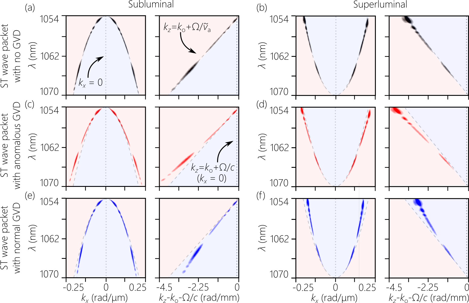
The spatio-temporal spectrum projected onto the -plane is obtained after implementing a spatial Fourier transform on the spectrally resolved wave front reflecting back from the SLM [Fig. 4]. The intensity distribution is then recorded by a CCD camera. The result is a parabola centered at of spatial bandwidth rad/m (corresponding to a spatial width of m at the pulse center) and a temporal bandwidth of nm (corresponding to a temporal linewidth of fs at the beam center). We plot in Fig. 5 the measured spectra for two classes of ST wave packets: subluminal in Fig. 5(a,c,e) with and , and superluminal in Fig. 5(b,d,f) with and . In each category we produce three distinct wave packets in free space: (1) a GVD-free wave packet that is propagation invariant [Fig. 5(a,b)]; (2) a dispersive ST wave packet endowed with anomalous GVD [Fig. 5(c,d)]; and (3) a dispersive ST wave packet endowed with normal GVD in free space [Fig. 5(e,f)]. In all cases, each spatial frequency is associated with a single wavelength . After introducing anomalous GVD , increases with respect to its GVD-free counterpart, corresponding to the required increase in propagation angle [Fig. 2(b,e)]. Alternatively, decreases with respect to the GVD-free wave packet after incorporating normal GVD [Fig. 5(e,f)] corresponding to the required decrease in propagation angle [Fig. 2(c,f)].
From these spectra in the -plane, we extract the spectral projection onto the -plane for the field in free space, making use of the relationship . This spectral projection for the GVD-free wave packets is a straight line [Fig. 5(a,b)]. These wave packets propagate invariantly in free space. However, the -projections curve away from that straight line in presence of GVD [Fig. 5(c-f)]. The dashed lines in the -plane [Fig. 5(c-f)] are the modified light-lines . Introducing anomalous GVD reduces , whereas incorporating normal GVD increases at each wavelength, which is consistent with our goal as illustrated in Fig. 2. Therefore, the measurements confirm that the targeted spatio-temporal spectra have indeed been produced in free space. We now proceed to verify that the expected propagation dynamics is produced in free space and in the dispersive media.
VI Dispersive space-time wave packets in free space
We reconstruct the spatio-temporal envelope of the wave-packet intensity profile at a given axial plane via linear interferometry making use of the initial laser pulses as a reference [36]; see Fig. 4. When the ST wave packet and the reference pulse overlap in space and time, spatially resolved fringes are recorded by a CCD camera whose visibility is used to reconstruct the wave packet profile as an optical delay is swept in the path of the reference pulse. Furthermore, the profiles of the ST wave packet at different axial planes are reconstructed by displacing the CCD camera to the target plane and compensating for the relative group delay between the ST wave packet (travelling at ) and the reference pulse (travelling at ).
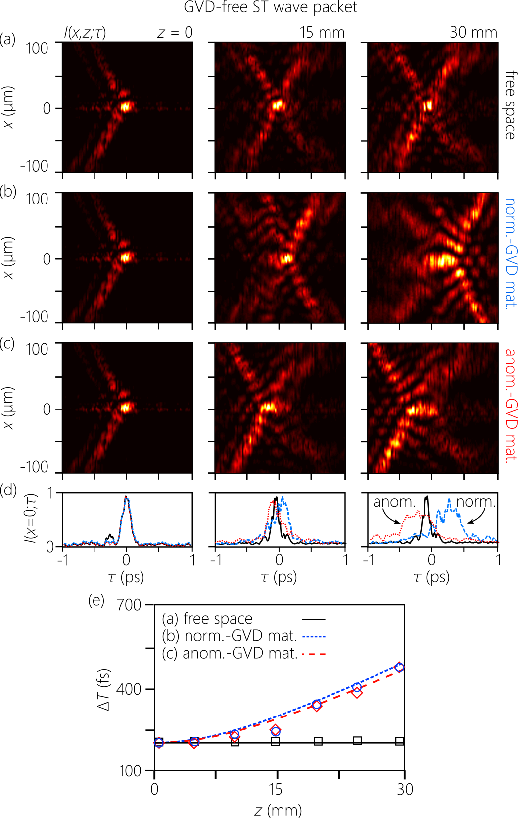
We start off with a subluminal () propagation-invariant ST wave packet in free space, and plot in Fig. 6(a) the measured profile at three axial planes in free space (, 15, and 30 mm) reconstructed in a frame traveling at . The X-shaped ST wave packet travels invariantly without distortion. The on-axis pulsewidth is constant in free space at fs. However, once this wave packet is coupled to a dispersive medium, pulse broadening is observed; see Fig. 6(b) for the normal-GVD medium and Fig. 6(c) for its anomalous-GVD counterpart. The pulsewidth increases monotonically from fs to fs after 30 mm in either medium [Fig. 6(d,e)].
Crucially, accompanying pulse broadening is an asymmetry between the structure of the wave packets in the normal- and anomalous-GVD media in regards to the direction of pulse broadening. In a normal-GVD medium, the pulse broadens towards later delays with respect to , whereas it boadens towards advanced delays. The distinct field structures that emerge in these two cases allow us to unambiguously delineate the wave packet at the output of the anomalous- and normal-GVD media. In Fig. 6(d) we plot the on-axis pulse profiles at , 15 mm, and 30 mm for the wave packets in Fig. 6(a-c) to highlight this asymmetry, which provides a clear signature of the type of GVD experienced by the wave packet. Note, however, that the rate of increase in pulsewidth with distance [Fig. 6(e)] does not depend on the sign of the GVD [1].
VII Propagation invariance in dispersive media
VII.1 Normal-GVD cancellation
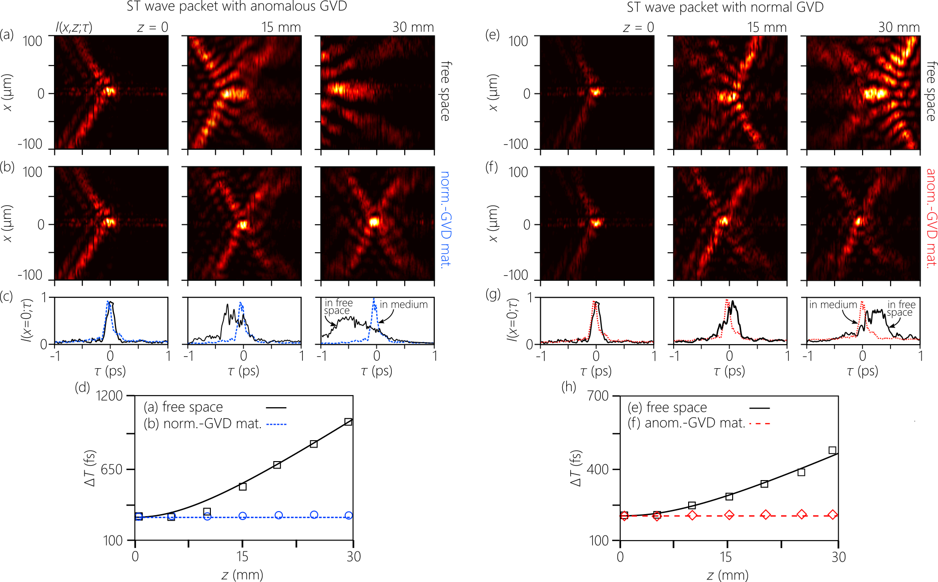
GVD-free propagation in ZnSe in the normal-GVD regime requires introducing anomalous GVD into the ST wave packet in free space. We set fs2/mm () for a subluminal ST wave packet and monitor its propagation in free space, whereupon it exhibits dispersive temporal broadening [Fig. 7(a)]. Moreover, the temporal asymmetry exhibited by the wave packet confirms that it experiences anomalous GVD in free space; compare Fig. 7(a) to Fig. 6(c). However, once the wave packet is coupled to ZnSe, this behavior is halted, and the wave packet travels GVD-free with a propagation-invariant spatio-temporal profile independently of the distance up to a 30-mm-thick ZnSe sample [Fig. 7(b)]. The on-axis pulse broadening in free space depicted in Fig. 7(c,d) is in quantitative agreement with the expectation based on the GVD coefficient introduced, whereas the pulsewidth is constant after GVD-cancellation.
VII.2 Anomalous-GVD cancellation
Propagation invariance in the anomalous-GVD sample requires introducing normal GVD into the ST wave packet in free space. Setting fs2/mm () and monitoring the propagation of the dispersive ST wave packet in free space reveals dispersive temporal broadening [Fig. 7(e)]. The temporal asymmetry in the wave packet spreading is consistent with normal GVD [compare Fig. 7(e) to Fig. 6(b)]. However, after traversing the chirped mirrors, the wave packet travels GVD-free with a propagation-invariant spatio-temporal profile independently of the sample thickness [Fig. 7(f)]. Once again, the broadening in the on-axis pulsewidth is in quantitative agreement with the expectation based on the GVD coefficient introduced, whereas the pulsewidth in the medium is constant after GVD-cancellation [Fig. 7(g,h)].
VII.3 Independence of the group velocity and GVD-cancellation
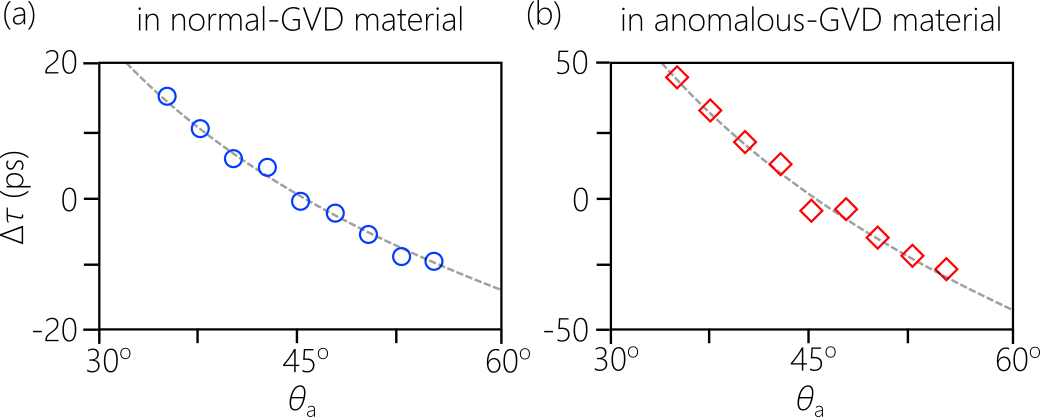
The measurements in Fig. 7 were carried out at a fixed group velocity in free space. In many nonlinear optical applications that benefit from GVD-cancellation, it is also useful to also control the wave-packet group velocity. This can help group-velocity matching between pulses at disparate wavelengths while exploiting long crystals. In our scheme, the angular dispersion profile can be controlled almost arbitrarily [Fig. 4]: each wavelength can be assigned a propagation angle independently of all other wavelengths, and we can thus tune and independently [60]. We demonstrate this capability in Fig. 8 where we measure the group delay in normal- and anomalous-GVD samples of fixed length ( mm) while varying the spectral tilt angle in free space. This results in tuning of the free-space group velocity and hence the group velocity in the medium (Eq. 2). Throughout, we maintain GVD-cancellation; that is, the wave packet is invariant after the sample independently of . As is increased continuously from the subluminal regime (, ) to the superluminal (, ) regime, the group velocity of the wave packet in the medium also increases, resulting in a concomitant drop in the group delay over the fixed sample length. This confirms that GVD-cancellation and group-velocity-tunability can be maintained independently of each other.
VIII Inverting the group-velocity dispersion
When GVD-cancellation is not achieved, the GVD coefficient in the medium is given by:
| (8) |
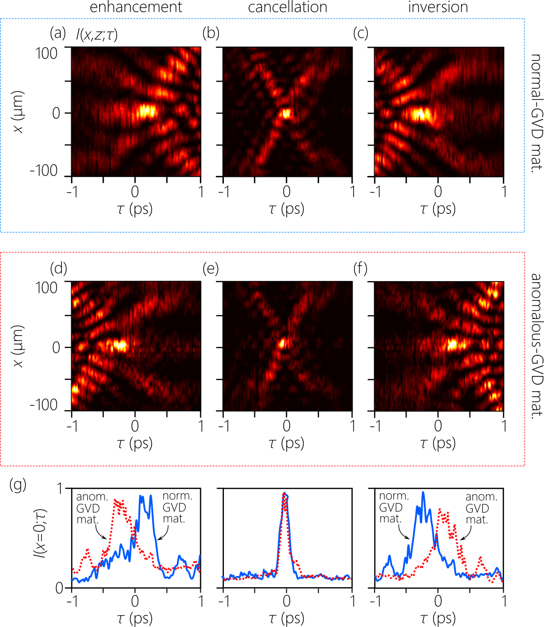
In other words, the effective GVD in the medium combines the intrinsic material GVD (due to chromatic dispersion) with the free-space GVD introduced into the ST wave packet (via non-differentiable angular dispersion), in addition to the negligible offset . By varying we can realize one of three different scenarios. First, the GVD introduced in free space can reinforce the GVD in the medium ( has the same sign as ), leading to GVD enhancement (). We present measurements for such a scenario in Fig. 9(a,d) where we enhance the dispersion in the normal-GVD medium by introducing normal-GVD in free space [Fig. 9(a)], and similarly enhance the dispersion in the anomalous-GVD regime by introducing anomalous GVD in free space [Fig. 9(d)]. Comparing Fig. 9(a,d) to Fig. 6(b,c) confirms the enhanced pulse broadening. Second, the GVD experienced by the wave packet in the medium can be cancelled by setting [Fig. 9(b,e)], which is the scenario dealt with above in Fig. 7.
Third, the effective GVD experienced by the wave packet in the medium can be inverted as shown in Fig. 9(c,f). By GVD-inversion we mean that the effective GVD coefficient in the medium has the opposite sign as that of the intrinsic chromatic dispersion in the medium (of course, the magnitudes need not be equal). In Fig. 9(c), the ST wave packet traveling in ZnSe in the normal-GVD regime instead encounters anomalous GVD. Here the anomalous GVD introduced in free space overcomes the normal GVD in the medium and renders it effectively an anomalous-GVD medium. Similarly, the ST wave packet in Fig. 9(f) traveling in the anomalous-GVD medium encounters instead normal GVD. This can be useful in exploiting media that have desirable nonlinear coefficients for particular interactions but whose sign of GVD at the wavelength of interest is opposite of what is needed.
IX Discussion and conclusion
We emphasize again the distinction between ‘dispersion compensation’ and ‘dispersion cancellation’. In the former, after a conventional pulse traverses a dispersive medium, an optical system compensates for the dispersion (in principle of any order or sign) encountered by removing the accumulated spectral phase. This can be accomplished using a spectral phase modulator [10] or other systems. By ‘dispersion cancellation’ we refer to modifying the structure of the optical field by introducing angular dispersion, such that it propagates invariantly in the dispersive medium. Whereas conventional angular dispersion (in TPFs) can cancel normal GVD but not anomalous GVD, we have demonstrated here that non-differentiable angular dispersion (in ST wave packets) enables GVD-cancellation in both the normal and anomalous regimes.
Although the existence of propagation-invariant ST wave packets in presence of normal or anomalous GVD was known theoretically, the lack of experimental strategies for producing non-differentiable angular dispersion precluded putting these predictions to test in the linear regime. Another obstacle faced previously is that the required ST wave packets were of the ‘baseband’ class; i.e., their spatial spectra are centered at [64]. Until recently, all experimentally generated ST wave packets in free space were of the ‘sideband’ variety; i.e., there spatial spectra are centered at and the low spatial frequencies in the vicinity of are excluded on physical grounds [64]. Examples include focus-wave modes [68, 69, 70] and X-waves [71, 72]. Both of these obstacles are overcome by exploiting the universal angular dispersion synthesizer in [59]. Although such an approach introduces arbitrary angular dispersion in one transverse dimension only, recent progress has extended this strategy to both transverse dimensions [73, 74, 75].
Although a previous experiment demonstrated normal-GVD cancellation in silica using modified X-waves [76, 77], no attempts at cancelling anomalous GVD by exploiting focus-wave modes, X-waves, or other sideband ST wave packets have been reported. Baseband ST wave packets have been synthesized via energy-inefficient spatio-temporal amplitude filtering for cancelling anomalous [78] and normal [79] GVD, but propagation invariance in presence of dispersion was not verified. Finally, theoretical studies have uncovered a host of structural field transitions for dispersion-free ST wave packets in dispersive media that have no analogs in free space, including a transition from X-shaped to O-shaped profiles while tuning the group velocity in presence of anomalous GVD [23], and even more complex transitions in the normal-GVD regime [22]. All such transitions occur at a fixed wavelength (in contrast to [80, 81] where the transition requires changing the GVD sign). None of these phenomena have been observed to date, and an O-shaped ST wave packet has not yet been reported. We anticipate that the work presented here can provide the platform for studying these structural dynamics in dispersive media.
In conclusion, we have realized – for the first time to the best of our knowledge – dispersion-free propagation in dispersive media symmetrically in the normal- and anomalous-GVD regimes. By incorporating non-differentiable angular dispersion into a pulsed field we produce ST wave packets whose group velocity and GVD coefficient can be tuned in free space independently of each other. We have confirmed dispersion-free propagation of 200-fs pulses at a wavelength m in ZnSe (normal GVD) and chirped Bragg mirrors (anomalous GVD). Moreover, because the GVD in the medium combines additively with the GVD introduced into the ST wave packet in free space, we have succeeded in demonstrating GVD-inversion: the wave packet experiences normal GVD while propagating in a medium in its anomalous-GVD regime, and vice versa. Moreover, we have demonstrated this unprecedented level of GVD control independently of the wave-packet group velocity, which can be tuned separately. These results are useful in multi-wavelength nonlinear interactions and quantum optics in long crystals.
Appendix: Coupling a tilted-pulse front to a dispersive medium
In an on-axis TPF in free space, the propagation angle with respect to the -axis takes the general form , with , , and we similarly expand and , , and ; where , , , , , and [16]. The last equation indicates that only anomalous GVD can be produced in free space on-axis with conventional angular dispersion. In a dispersive medium, the expansion coefficients for and are: , , , , , and .
Because is invariant across a planar interface at normal incidence, matching the first-order expansion coefficients for yields , which can be recognized as the law of refraction for TPFs at normal incidence. Dispersion-free propagation in the medium requires that . Only normal GVD can be cancelled. The corresponding TPF in free space has a GVD coefficient . Therefore, GVD-cancellation requires exercising control over only first-order angular dispersion. To simplify the synthesis of the TPF in free space, we set for . This assumption does not lead to the elimination of , which is given by . The transverse wave number is , which is differentiable with respect to everywhere. In free space, , so that .
Although the TPF in the material is GVD-free, higher-order dispersion terms nevertheless exist because of the term,. Of course one may eliminate the term by including an appropriate term in free space. However, this would add to the complexity of the system. Indeed, no known optical device – besides the universal angular-dispersion synthesizer [59] – has reported independent control over both and .
ACKNOWLEDGMENTS
The authors acknowledge the support of the Office of Naval Research (ONR, Grant Nos. N00014-17-1-2458 and N00014-20-1-2789).
The authors declare no conflicts of interest.
DATA AVAILABILITY
The data that support the findings of this study are available from the corresponding author upon reasonable request.
References
- Saleh and Teich [2007] B. E. A. Saleh and M. C. Teich, Principles of Photonics (Wiley, 2007).
- Weiner [2009] A. M. Weiner, Ultrafast Optics (John Wiley & Sons, Inc., 2009).
- Strickland and Mourou [1985] D. Strickland and G. Mourou, Compression of amplified chirped optical pulses, Opt. Commun. 56, 3219 (1985).
- Fork et al. [1984] R. L. Fork, O. E. Martinez, and J. P. Gordon, Negative dispersion using pairs of prisms, Opt. Lett. 9, 150 (1984).
- Martinez [1987] O. E. Martinez, 3000 times grating compressor with positive group velocity dispersion: Application to fiber compensation in m region, IEEE J. Quantum Electron. 23, 59 (1987).
- White et al. [1993] W. E. White, F. G. Patterson, R. L. Combs, D. F. Price, and R. L. Shepherd, Compensation of higher-order frequency-dependent phase terms in chirped-pulse amplification systems, Opt. Lett. 18, 1343 (1993).
- Lemoff and Barty [1993] B. E. Lemoff and C. P. J. Barty, Quintic-phase-limited, spatially uniform expansion and recompression of ultrashort optical pulses, Opt. Lett. 18, 1651 (1993).
- Kane and Squier [1997a] S. Kane and J. Squier, Grism-pair stretcher–compressor system for simultaneous second- and third-order dispersion compensation in chirped-pulse amplification, J. Opt. Soc. Am. B 14, 661 (1997a).
- Kane and Squier [1997b] S. Kane and J. Squier, Fourth-order-dispersion limitations of aberration-free chirped-pulse amplification systems, J. Opt. Soc. Am. B 14, 1237 (1997b).
- Weiner [2000] A. M. Weiner, Femtosecond pulse shaping using spatial light modulators, Rev. Sci. Instrum. 71, 1929 (2000).
- Runge et al. [2020] A. F. J. Runge, D. D. Hudson, K. K. K. Tam, C. M. de Sterke, and A. Blanco-Redondo, The pure-quartic soliton laser, Nat. Photon. 14, 492 (2020).
- Torres et al. [2010] J. P. Torres, M. Hendrych, and A. Valencia, Angular dispersion: an enabling tool in nonlinear and quantum optics, Adv. Opt. Photon. 2, 319 (2010).
- Szatmári et al. [1996] S. Szatmári, P. Simon, and M. Feuerhake, Group-velocity-dispersion-compensated propagation of short pulses in dispersive media, Opt. Lett. 21, 1156 (1996).
- Fülöp and Hebling [2010] J. A. Fülöp and J. Hebling, Applications of tilted-pulse-front excitation, in Recent Optical and Photonic Technologies, edited by K. Y. Kim (InTech, 2010).
- Martinez et al. [1984] O. E. Martinez, J. P. Gordon, and R. L. Fork, Negative group-velocity dispersion using refraction, J. Opt. Soc. Am. A 1, 1003 (1984).
- Porras et al. [2003a] M. A. Porras, G. Valiulis, and P. Di Trapani, Unified description of Bessel X waves with cone dispersion and tilted pulses, Phys. Rev. E 68, 016613 (2003a).
- Porras et al. [2003b] M. A. Porras, S. Trillo, C. Conti, and P. Di Trapani, Paraxial envelope X waves, Opt. Lett. 28, 1090 (2003b).
- Longhi [2004] S. Longhi, Localized subluminal envelope pulses in dispersive media, Opt. Lett. 29, 147 (2004).
- Porras and Di Trapani [2004] M. A. Porras and P. Di Trapani, Localized and stationary light wave modes in dispersive media, Phys. Rev. E 69, 066606 (2004).
- Christodoulides et al. [2004] D. N. Christodoulides, N. K. Efremidis, P. Di Trapani, and B. A. Malomed, Bessel X waves in two- and three-dimensional bidispersive optical systems, Opt. Lett. 29, 1446 (2004).
- Mills et al. [2012] M. S. Mills, G. A. Siviloglou, N. Efremidis, T. Graf, E. M. Wright, J. V. Moloney, and D. N. Christodoulides, Localized waves with spherical harmonic symmetries, Phys. Rev. A 86, 063811 (2012).
- Malaguti and Trillo [2009] S. Malaguti and S. Trillo, Envelope localized waves of the conical type in linear normally dispersive media, Phys. Rev. A 79, 063803 (2009).
- Malaguti et al. [2008] S. Malaguti, G. Bellanca, and S. Trillo, Two-dimensional envelope localized waves in the anomalous dispersion regime, Opt. Lett. 33, 1117 (2008).
- Di Trapani et al. [2003] P. Di Trapani, G. Valiulis, A. Piskarskas, O. Jedrkiewicz, J. Trull, C. Conti, and S. Trillo, Spontaneously generated X-shaped light bullets, Phys. Rev. Lett. 91, 093904 (2003).
- Faccio et al. [2006] D. Faccio, M. A. Porras, A. Dubietis, F. Bragheri, A. Couairon, and P. Di Trapani, Conical emission, pulse splitting, and X-wave parametric amplification in nonlinear dynamics of ultrashort light pulses, Phys. Rev. Lett. 96, 193901 (2006).
- Faccio et al. [2007] D. Faccio, A. Averchi, A. Couairon, M. Kolesik, J. Moloney, A. Dubietis, G. Tamosauskas, P. Polesana, A. Piskarskas, and P. D. Trapani, Spatio-temporal reshaping and X wave dynamics in optical filaments, Opt. Express 15, 13077 (2007).
- Porras et al. [2007] M. A. Porras, A. Dubietis, A. Matijošius, R. Piskarskas, F. Bragheri, A. Averchi, and P. Di Trapani, Characterization of conical emission of light filaments in media with anomalous dispersion, J. Opt. Soc. Am. B 24, 581 (2007).
- Kondakci and Abouraddy [2016] H. E. Kondakci and A. F. Abouraddy, Diffraction-free pulsed optical beams via space-time correlations, Opt. Express 24, 28659 (2016).
- Parker and Alonso [2016] K. J. Parker and M. A. Alonso, The longitudinal iso-phase condition and needle pulses, Opt. Express 24, 28669 (2016).
- Porras [2017] M. A. Porras, Gaussian beams diffracting in time, Opt. Lett. 42, 4679 (2017).
- Efremidis [2017] N. K. Efremidis, Spatiotemporal diffraction-free pulsed beams in free-space of the Airy and Bessel type, Opt. Lett. 42, 5038 (2017).
- Porras [2018] M. A. Porras, Nature, diffraction-free propagation via space-time correlations, and nonlinear generation of time-diffracting light beams, Phys. Rev. A 97, 063803 (2018).
- Yessenov et al. [2019a] M. Yessenov, B. Bhaduri, H. E. Kondakci, and A. F. Abouraddy, Weaving the rainbow: Space-time optical wave packets, Opt. Photon. News 30, 34 (2019a).
- Yessenov et al. [2022] M. Yessenov, L. A. Hall, K. L. Schepler, and A. F. Abouraddy, Space-time wave packets, arXiv:2201.08297 (2022).
- Wong and Kaminer [2017] L. J. Wong and I. Kaminer, Ultrashort tilted-pulsefront pulses and nonparaxial tilted-phase-front beams, ACS Photon. 4, 2257 (2017).
- Kondakci and Abouraddy [2019] H. E. Kondakci and A. F. Abouraddy, Optical space-time wave packets of arbitrary group velocity in free space, Nat. Commun. 10, 929 (2019).
- Yessenov et al. [2019b] M. Yessenov, B. Bhaduri, L. Mach, D. Mardani, H. E. Kondakci, M. A. Alonso, G. A. Atia, and A. F. Abouraddy, What is the maximum differential group delay achievable by a space-time wave packet in free space?, Opt. Express 27, 12443 (2019b).
- Yessenov and Abouraddy [2019] M. Yessenov and A. F. Abouraddy, Changing the speed of coherence in free space, Opt. Lett. 44, 5125 (2019).
- Kondakci and Abouraddy [2018] H. E. Kondakci and A. F. Abouraddy, Self-healing of space-time light sheets, Opt. Lett. 43, 3830 (2018).
- Bhaduri et al. [2020] B. Bhaduri, M. Yessenov, and A. F. Abouraddy, Anomalous refraction of optical spacetime wave packets, Nat. Photon. 14, 416 (2020).
- Allende Motz et al. [2021a] A. M. Allende Motz, M. Yessenov, and A. F. Abouraddy, Isochronous space-time wave packets, Opt. Lett. 46, 2260 (2021a).
- Yessenov et al. [2021a] M. Yessenov, B. Bhaduri, and A. F. Abouraddy, Refraction of space-time wave packets: I. Theoretical principles, arXiv:2104.12965 (2021a).
- Allende Motz et al. [2021b] A. M. Allende Motz, M. Yessenov, B. Bhaduri, and A. F. Abouraddy, Refraction of optical space-time wave packets: II. Experiments at normal incidence, arXiv:2104.12969 (2021b).
- Yessenov et al. [2021b] M. Yessenov, A. M. Allende Motz, B. Bhaduri, and A. F. Abouraddy, Refraction of optical space-time wave packets: III. Experiments at oblique incidence, arXiv:2104.12972 (2021b).
- Hall et al. [2021a] L. A. Hall, M. Yessenov, S. A. Ponomarenko, and A. F. Abouraddy, The space-time Talbot effect, APL Photon. 6, 056105 (2021a).
- Kondakci et al. [2019] H. E. Kondakci, M. A. Alonso, and A. F. Abouraddy, Classical entanglement underpins the propagation invariance of space-time wave packets, Opt. Lett. 44, 2645 (2019).
- Bhaduri et al. [2019] B. Bhaduri, M. Yessenov, D. Reyes, J. Pena, M. Meem, S. R. Fairchild, R. Menon, M. C. Richardson, and A. F. Abouraddy, Broadband space-time wave packets propagating 70 m, Opt. Lett. 44, 2073 (2019).
- Yessenov et al. [2020] M. Yessenov, B. Bhaduri, P. J. Delfyett, and A. F. Abouraddy, Free-space optical delay line using space-time wave packets, Nat. Commun. 11, 5782 (2020).
- Shiri et al. [2020a] A. Shiri, M. Yessenov, S. Webster, K. L. Schepler, and A. F. Abouraddy, Hybrid guided space-time optical modes in unpatterned films, Nat. Commun. 11, 6273 (2020a).
- Schepler et al. [2020] K. L. Schepler, M. Yessenov, Y. Zhiyenbayev, and A. F. Abouraddy, Space–time surface plasmon polaritons: A new propagation-invariant surface wave packet, ACS Photon. 7, 2966 (2020).
- Shiri et al. [2020b] A. Shiri, M. Yessenov, R. Aravindakshan, and A. F. Abouraddy, Omni-resonant space-time wave packets, Opt. Lett. 45, 1774 (2020b).
- Kibler and Béjot [2021] B. Kibler and P. Béjot, Discretized conical waves in multimode optical fibers, Phys. Rev. Lett. 126, 023902 (2021).
- Béjot and Kibler [2021] P. Béjot and B. Kibler, Spatiotemporal helicon wavepackets, ACS Photon. 8, 2345 (2021).
- Ruano et al. [2021] P. N. Ruano, C. W. Robson, and M. Ornigotti, Localized waves carrying orbital angular momentum in optical fibers, J. Opt. 23, 075603 (2021).
- Guo and Fan [2021] C. Guo and S. Fan, Generation of guided space-time wave packets using multilevel indirect photonic transitions in integrated photonics, Phys. Rev. Research 3, 033161 (2021).
- Hall et al. [2021b] L. A. Hall, M. Yessenov, and A. F. Abouraddy, Space-time wave packets violate the universal relationship between angular dispersion and pulse-front tilt, Opt. Lett. 46, 1672 (2021b).
- Hall and Abouraddy [2021a] L. A. Hall and A. F. Abouraddy, Realizing normal group-velocity dispersion in free space via angular dispersion, Opt. Lett. 46, 5421 (2021a).
- Hall and Abouraddy [2021b] L. A. Hall and A. F. Abouraddy, Consequences of non-differentiable angular dispersion in optics: Tilted pulse fronts versus space-time wave packets, arXiv:2109.07039 (2021b).
- Hall and Abouraddy [2021c] L. A. Hall and A. F. Abouraddy, A universal angular-dispersion synthesizer, arXiv:2109.13987 (2021c).
- Yessenov et al. [2021c] M. Yessenov, L. A. Hall, and A. F. Abouraddy, Engineering the optical vacuum: Arbitrary magnitude, sign, and order of dispersion in free space using space-time wave packets, ACS Photonics 8, 2274 (2021c).
- Gordon and Fork [1984] J. P. Gordon and R. L. Fork, Optical resonator with negative dispersion, Opt. Lett. 9, 153 (1984).
- Donnelly and Ziolkowski [1993] R. Donnelly and R. Ziolkowski, Designing localized waves, Proc. R. Soc. Lond. A 440, 541 (1993).
- Kondakci and Abouraddy [2017] H. E. Kondakci and A. F. Abouraddy, Diffraction-free space-time beams, Nat. Photon. 11, 733 (2017).
- Yessenov et al. [2019c] M. Yessenov, B. Bhaduri, H. E. Kondakci, and A. F. Abouraddy, Classification of propagation-invariant space-time light-sheets in free space: Theory and experiments, Phys. Rev. A 99, 023856 (2019c).
- He et al. [2021] H. He, C. Guo, and M. Xiao, Non-dispersive space-time wave packets propagating in dispersive media, arXiv:2109.00782 (2021).
- Yessenov et al. [2021d] M. Yessenov, S. Faryadras, S. Benis, D. J. Hagan, E. W. Van Stryland, and A. F. Abouraddy, Refraction of space-time wave packets in a dispersive medium, arXiv:2112.04003 (2021d).
- Marple [1964] D. T. F. Marple, Refractive index of ZnSe, ZnTe, and CdTe, J. Appl. Phys. 35, 539 (1964).
- Brittingham [1983] J. N. Brittingham, Focus wave modes in homogeneous Maxwell’s equations: Transverse electric mode, J. Appl. Phys. 54, 1179 (1983).
- Reivelt and Saari [2000] K. Reivelt and P. Saari, Optical generation of focus wave modes, J. Opt. Soc. Am. A 17, 1785 (2000).
- Reivelt and Saari [2002] K. Reivelt and P. Saari, Experimental demonstration of realizability of optical focus wave modes, Phys. Rev. E 66, 056611 (2002).
- Lu and Greenleaf [1992] J.-Y. Lu and J. F. Greenleaf, Nondiffracting X waves – exact solutions to free-space scalar wave equation and their finite aperture realizations, IEEE Trans. Ultrason. Ferroelec. Freq. Control 39, 19 (1992).
- Saari and Reivelt [1997] P. Saari and K. Reivelt, Evidence of X-shaped propagation-invariant localized light waves, Phys. Rev. Lett. 79, 4135 (1997).
- Guo et al. [2021] C. Guo, M. Xiao, M. Orenstein, and S. Fan, Structured 3D linear space-time light bullets by nonlocal nanophotonics, Light Sci. Appl. 10, 160 (2021).
- Pang et al. [2021] K. Pang, K. Zou, H. Song, Z. Zhao, A. Minoofar, R. Zhang, H. Song, H. Zhou, X. Su, C. Liu, N. Hu, M. Tur, and A. E. Willner, Simulation of near-diffraction- and near-dispersion-free oam pulses with controllable group velocity by combining multiple frequencies, each carrying a bessel mode, Opt. Lett. 46, 4678 (2021).
- Yessenov et al. [2021e] M. Yessenov, J. Free, Z. Chen, E. G. Johnson, M. P. J. Lavery, M. A. Alonso, and A. F. Abouraddy, Space-time wave packets localized in all dimensions, arXiv:2111.03095 (2021e).
- Sõnajalg and Saari [1996] H. Sõnajalg and P. Saari, Suppression of temporal spread of ultrashort pulses in dispersive media by bessel beam generators, Opt. Lett. 21, 1162 (1996).
- Sõnajalg et al. [1997] H. Sõnajalg, M. Rätsep, and P. Saari, Demonstration of the Bessel-X pulse propagating with strong lateral and longitudinal localization in a dispersive medium, Opt. Lett. 22, 310 (1997).
- Dallaire et al. [2009] M. Dallaire, N. McCarthy, and M. Piché, Spatiotemporal bessel beams: theory and experiments, Opt. Express 17, 18148 (2009).
- Jedrkiewicz et al. [2013] O. Jedrkiewicz, Y.-D. Wang, G. Valiulis, and P. Di Trapani, One dimensional spatial localization of polychromatic stationary wave-packets in normally dispersive media, Opt. Express 21, 25000 (2013).
- Porras et al. [2005] M. A. Porras, A. Dubietis, E. Kuc̆inskas, F. Bragheri, V. Degiorgio, A. Couairon, D. Faccio, and P. Di Trapani, From X- to O-shaped spatiotemporal spectra of light filaments in water, Opt. Lett. 30, 3398 (2005).
- Panov et al. [2021] N. A. Panov, D. E. Shipilo, I. A. Nikolaeva, V. O. Kompanets, S. V. Chekalin, and O. G. Kosareva, Continuous transition from X- to O-shaped angle-wavelength spectra of a femtosecond filament in a gas mixture, Phys. Rev. A 103, L021501 (2021).