Determination of topological edge quantum numbers of fractional quantum Hall phases
Department of Physics, Indian Institute of Science, Bangalore, 560012, India.
Department of Microtechnology and Nanoscience (MC2),Chalmers University of Technology, S-412 96 Göteborg, Sweden.
National Institute of Material Science, 1-1 Namiki, Tsukuba 305-0044, Japan.
Institute for Quantum Materials and Technologies, Karlsruhe Institute of Technology, 76021 Karlsruhe, Germany.
Institut für Theorie der Kondensierten Materie, Karlsruhe Institute of Technology, 76128 Karlsruhe, Germany.
Petersburg Nuclear Physics Institute, 188300 St. Petersburg, Russia.
L. D. Landau Institute for Theoretical Physics RAS, 119334 Moscow, Russia.
Department of Condensed Matter Physics, Weizmann Institute of Science, Rehovot 76100, Israel.
To determine the topological quantum numbers of fractional quantum Hall (FQH) states hosting counter-propagating (CP) downstream () and upstream () edge modes, it is pivotal to study quantized transport both in the presence and absence of edge mode equilibration. While reaching the non-equilibrated regime is challenging for charge transport, we target here the thermal Hall conductance , which is purely governed by edge quantum numbers and . Our experimental setup is realized with a hBN encapsulated graphite gated monolayer graphene device. For temperatures up to , our measured at 2/3 and 3/5 (with CP modes) match the quantized values of non-equilibrated regime , where is a quanta of . With increasing temperature, decreases and eventually takes the value of equilibrated regime . By contrast, at 1/3 and 2/5 (without CP modes), remains robustly quantized at independent of the temperature. Thus, measuring the quantized values of at two regimes, we determine the edge quantum numbers, which opens a new route for finding the topological order of exotic non-Abelian FQH states.
Introduction. In the quantum Hall (QH) regime, transport occurs in one-dimensional gapless edge modes, which reflect the topology of the bulk filling factor . In integer QH (IQH) states and in a certain subclass of fractional QH (FQH) states, only downstream edge modes ( of them) exist, whose chirality is dictated by the direction of the applied magnetic field[1, 2]. At the same time, the edge structure of a majority of FQH states, including, in particular, the “hole-like” states , is more complicated. In addition to the downstream edge modes, the presence of upstream modes () leads to complex transport behaviour[1, 2, 3, 4, 5, 6]. In this situation, the measured values of the electrical conductance () depends on the extent of the charge equilibration between the counter-propagating downstream and upstream modes. For example, the state hosts two counter-propagating modes: a downstream mode, , and an upstream mode[3]. With full charge equilibration, the two-terminal conductance becomes[7, 8, 9, 10] ; on the other hand, in the absence of charge equilibration, is equal to[8, 10] . The observation of a crossover from to is essential to establish the proposed edge structure. This crossover has indeed been observed in carefully engineered double-quantum-well structure, allowing control of the equilibration[11]. At the same time, a similar demonstration is lacking in experiments on a conventional edge (the boundary of a FQH state), where is always found to be . The reason is that the small value of the charge equilibration length makes it difficult to access the non-equilibrated regime. A small deviation from indicating a beginning of the crossover towards was observed for the spin-unpolarized FQH state[12].
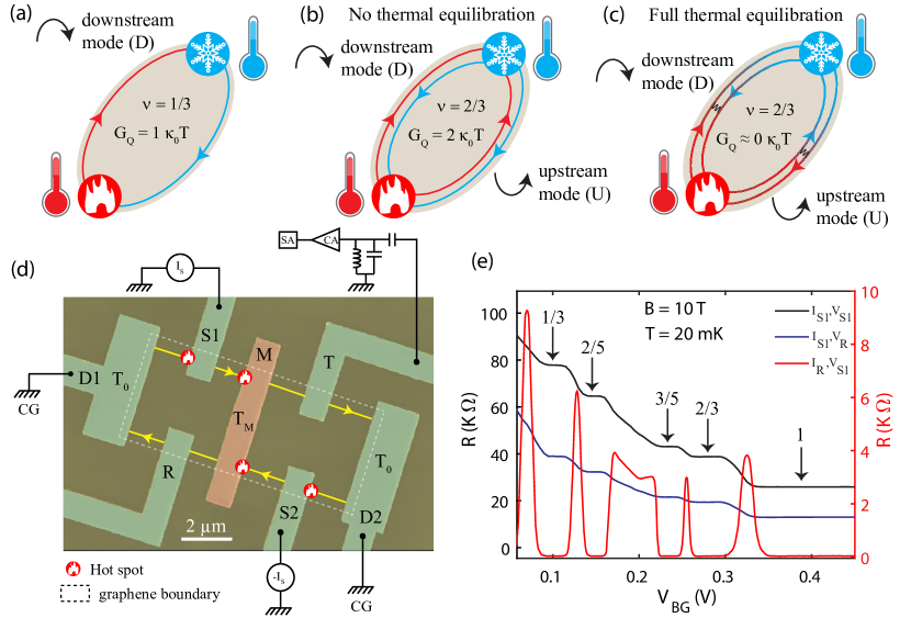
Measurements of thermal conductance have recently emerged as a powerful tool to detect the edge structure of FQH states[13, 14, 15, 16, 17, 18]. Such measurements are highly useful for “counting” edge modes and can also detect charge neutral Majorana modes[16, 19]. For IQH states and FQH states with only downstream modes, the quantized thermal conductance is given by , where , is the Boltzmann constant, is the Planck constant, and is the temperature[14]. A schematic illustration of the heat flow for such a state ( in this example) is depicted in Fig. 1(a). On the other hand, for hole-like FQH states, the presence of upstream modes renders the value of strongly dependent on the extent of thermal equilibration between CP modes. This leads to a crossover[8] of from a non-equilibrated quantized value of to the asymptotic value of full equilibration . Such a crossover behaviour of heat conductance is schematically shown in Fig. 1(b,c) for . While the fully-equilibrated and non-equilibrated limiting cases of have been reported in disparate GaAs/AlGaAs based 2DEG devices[15, 16, 20], and in graphene only the non-equilibrated values have been observed[18], a crossover of from the non-equilibrated to the fully equilibrated limit in a single device has remained unattainable. This has remained one of the long-standing challenges on the path to reveal the detailed edge structure of FQH states. Achieving this goal would further help to settle the topological order of more complex non-Abelian even-denominator FQH states and may be useful for revealing possible reconstruction of QH edges.
In the present work we report on thermal conductance measurements (as a function of temperature ) of FQH states without CP modes ( and ) and with CP modes ( and ), realized in a encapsulated graphite gated high-mobility monolayer graphene device. Our key findings are the following: (1) At the base temperature (), for and is found to be and , respectively, which matches the non-equilibrated limit . These values remain constant up to . (2) With further increase of temperature, for decreases, saturating at the equilibrated limit for . The crossover from the non-equilibrated to the equilibrated regime of is observed for too. In this case, the heat transport in the equilibrated regime is of diffusive character, with the limiting value that is approached in a power-law way as a function of temperature. Our measurements show a drop of that reaches a value at , continuing to decrease towards zero. (3) For and FQH states (no CP modes), is found to be and , respectively, independent of the electron temperature.
Device schematic and response: To measure the thermal conductance, we have used a graphite-gated graphene device, where the graphene is encapsulated between two hBN layers. The details of the device fabrication is described in Methods. Similar to our previous work [17, 18], our device consists of a small floating metallic reservoir, which is connected to graphene channel via one-dimensional edge contacts, as shown in Fig. 1(d). To measure the electrical conductance, we used the standard lock-in technique whereas the thermal conductance measurement was performed with noise thermometry [21, 15, 16, 17, 18, 22] (see SI). In Fig. 1(e), the black curve represents the measured resistance () at the source contact () as a function of the graphite gate voltage (). Well developed plateaus appear at , , and . The blue curve shows the measured resistance along the reflected path (at contact ) from the floating contact. Measured resistances along the reflected path is exactly half of the resistance measured at the source contact, suggesting equal partitioning of injected current to both the transmitted and reflected side (see SI). The red curve in Fig. 1(e) shows the resistance measured at contact , while the current is injected from the contact . This resistance in this configuration has the same properties as a longitudinal resistance: in the absence of bulk transport, the voltage is determined by the equilibrium potential of the ground contact D1. The observation of the vanishing resistance plateaus further supports the formation of well developed FQH states. It should be noted that the measured resistance values suggest full charge equilibration in our device (see SI).
Thermal conductance measurement: In contrast to our previous work [17, 18], to measure the thermal conductance, we simultaneously inject the DC currents and at two contacts and , respectively. Both injected currents flow towards the floating reservoir. This is done in order to keep the potential of the floating contact to be the same as that of all drain contacts. In this configuration, the dissipated power at the floating reservoir due to Joule heating is given as (see SI). This power dissipation leads to increase of the electron temperature in the floating reservoir. The new steady state temperature is determined by the heat balance relation [21, 15, 16, 17, 18, 23, 24]
| (1) |
Here, is the electronic contribution of the heat current via chiral edge modes, and is the heat loss via electron-phonon cooling. The temperature is obtained by measuring the excess thermal noise [21, 15, 16, 17, 18] along the outgoing edge channels using the Nyquist-Johnson relation
| (2) |
For our hBN encapsulated graphite gated devices [18], the electron-phonon contribution (second term in Eq. 1) was found to be negligible for (see SI). From Eq. 1, one finds , which yields the sought thermal conductance .
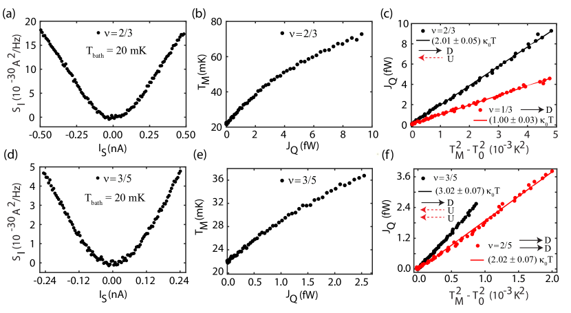
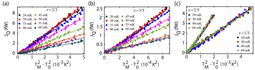
In Fig. 2, we show the detailed procedure to extract the quantized at the bath temperature . The measured excess thermal noise is plotted as a function of current for 2/3 and 3/5 in Fig. 2(a) and Fig. 2(d), respectively. The resulting heating of the floating reservoir is made manifest by the increase in excess thermal noise with application of the source current . The noise and current axes of Fig. 2(a) and 2(d) are converted to and , yielding Fig. 2(b) for and Fig. 2(e) for , respectively. To extract , the heat current is plotted as a function of for (red) and 2/3 (black) in Fig. 2(c) and for (red) and 3/5 (black) in Fig. 2(f). The solid circles represent the experimental data, while the solid lines are the linear fits with (red) and (black) for and 2/3, respectively, in Fig. 2(c) and (red) and (black) for and 3/5, respectively, in Fig. 2(f). To further study the temperature dependence of the thermal conductance, is plotted as a function of at several values of the bath temperature for 2/3 in Fig. 3(a) and for 3/5 in Fig. 3(b). An analogous plot is shown for (solid circles) and (solid stars) in Fig. 3(c). The slopes of linear fits to the data in these figures allow us to extract the values of . Whereas the data for the 2/3 and 3/5 states show an explicit dependence of on bath temperature, the thermal conductance remains independent of the temperature for the 1/3 and 2/5 states, Fig. 3(c).
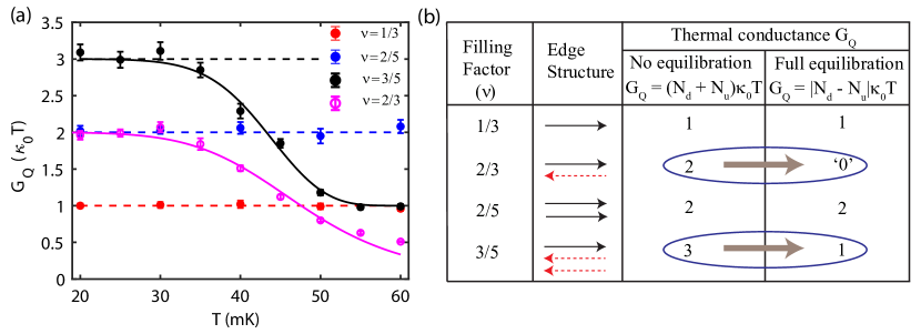
Results: In Fig. 4(a), we plot the thermal conductance (extracted from the slope of the linear fits to the data in Fig. (3) as a function of the bath temperature for (red), (blue), (magenta), and (black). For completeness, we also show the proposed edge structure of studied FQH states and corresponding theoretically expected values in Fig. 4(b). As evident from the edge structure, for (red) and (blue), the values should not depend on temperature as there are no CP modes. This is indeed observed in our data shown in Fig. 4(a). On the other hand, for the hole-like state with and , we observe the crossover from non-equilibrated regime of to equilibrated regime of . A similar crossover is observed also for the state with . For this state, at low temperatures, the non-equilibrated regime of is observed. In the equilibrated regime, the transport in this situation () is diffusive in nature, so that is expected to tend to zero as in the long-length limit. Since our device channel length is limited to , we observe a drop of down to a finite value of at . Our result is the first experimental demonstration of the crossover from non-equilibrated to fully equilibrated heat transport in FQH edges with CP modes. Observation of such crossover in a single device has been a long-sought goal, as it can settle the ambiguity in the ground state of the complex even denominator FQH states (e.g., at filling ), which remains a subject of active debate.
Discussion. In this section, we would like to discuss a few additional points related to the expected theoretical regimes of equilibration, the accuracy of our measurement, and temperature exponents of the thermal equilibration lengths.
(1) The quantized value of the thermal conductance in the non-equilibrated regime, , where is the thermal equilibration length, strictly holds if there is no back-scattering of heat at interfaces with contacts. This is fulfilled under an additional condition where is the thermal length. In the intermediate regime , a correction to this value is expected to emerge [25, 8, 20]. Thus, the non-equilibrated regime may, in fact, be expected to be split into two plateaus, which is, however, not observed in our experiment.
(2) The experimental determination of the thermal conductance follows the approach of several preceding works that use two implicit assumptions: (i) current fluctuations propagating from the central contact satisfy the thermal equilibrium distribution, implying the Johnson-Nyquist relation between the contact temperature and the noise; (ii) all power dissipated close to the central contact heats it. When all modes propagate downstream, both these assumptions strictly hold. However, for edges with CP modes, the situation may be somewhat more delicate and some deviations from the assumptions (i) and (ii) may emerge. This issue was discussed in Ref. [20], where corrections to the procedure of extraction of were obtained that slightly reduce the experimental value of . We do not include these corrections in the present work. First, they would not affect the identification of the asymptotic regimes. Second, the values of that we find without including these corrections agree remarkably with the quantized values, both for the non-equilibrated regime (as was also found for bilayer graphene in Ref. [18]) and in the equilibrated limit. It remains to see which features of our device favor this remarkable agreement. We would like to note that the precise determination of depends on the accuracy of electron temperature and gain of the amplification chain, which are shown in details in SI.
(3) According to theoretical predictions, the crossover of between the asymptotic limits of no thermal equilibration () and perfect thermal equilibration () is described by a function of the dimensionless ratio , with the thermal equilibration length scaling as a power of temperature, . Explicit forms of the crossover functions for and states are given below in Methods. Our experimental data are well described by these forms. At the same time, the values of the exponent that are obtained from the fits turn out to be unexpectedly large: for and for , well above expected in the vicinity of the strong-disorder fixed points [6, 7, 8]. This implies that the crossover is surprisingly sharp as a function of temperature. Various mechanisms are known that may in principle lead to large values of in correlated 1D systems. This may happen if the energy relaxation is controlled by multiparticle processes, or else, by nonlinearities of the edge spectrum. We leave a detailed investigation of this issue in the present context to future research.
Conclusion. The findings of this work are a remarkable manifestation of an interplay of equilibration (or absence thereof) and topology in FQH transport. While the charge transport is in the equilibrated regime, the heat transport crosses over from the non-equilibrated to equilibrated regime, with both asymptotic limits characterized by topologically quantized heat conductances determined by edge quantum numbers. We expect that this physics should be relevant also to other FQH states and materials. In particular, interpretation of the experimentally measured thermal conductance at the non-Abelian state requires assumptions about the presence, absence, or partial character of thermal equilibration [26, 27, 28, 29, 30]. Measurement of the full crossover from the non-equilibrated to equilibrated regime would permit to unambiguously resolve this problem.
Methods
0.1 Device fabrication and measurement scheme:
In our experiment, encapsulated device (heterostructure of hBN/single layer graphene(SLG)/hBN/graphite) was made using the standard dry transfer pick-up technique [31]. Fabrication of this heterostructure involved mechanical exfoliation of hBN and graphite crystals on oxidized silicon wafer using the widely used scotch tape technique. First, a hBN of thickness of nm was picked up at C using a Poly-Bisphenol-A-Carbonate (PC) coated Polydimethylsiloxane (PDMS) stamp placed on a glass slide, attached to tip of a home built micromanipulator. This hBN flake was aligned on top of previously exfoliated SLG. SLG was picked up at C. The next step involved the pick up of bottom hBN ( nm). This bottom hBN was picked up using the previously picked-up hBN/SLG following the previous process. This hBN/SLG/hBN heterostructure was used to pick-up the graphite flake following the previous step. Finally, this resulting hetrostructure (hBN/SLG/hBN/graphite) was dropped down on top of an oxidized silicon wafer of thickness 285 nm at temperature C. To remove the residues of PC, this final stack was cleaned in chloroform (\chCHCl_3) overnight followed by cleaning in acetone and iso-propyl alcohol (IPA). After this, Poly-methyl-methacrylate (PMMA) photoresist was coated on this heterostructure to define the contact regions in the Hall probe geometry using electron beam lithography (EBL). Apart from the conventional Hall probe geometry, we defined a region of 5.5 area in the middle of SLG flake, which acts as floating metallic reservoir upon edge contact metallization. After EBL, reactive ion etching (mixture of \chCHF_3 and \chO_2 gas with flow rate of 40 sccm and 4 sccm, respectively at C with RF power of 60W) was used to define the edge contact. The etching time was optimized such that the bottom hBN did not etch completely to isolate the contacts from bottom graphite flake, which was used as the back gate. Finally, thermal deposition of Cr/Pd/Au (3/12/60 nm) was done in an evaporator chamber having base pressure of mbar. After deposition, a lift-off procedure was performed in hot acetone and IPA. This results in a Hall bar device along with the floating metallic reservoir connected to the both sides of SLG by the edge contacts. The schematics of the device and measurement set-up are shown in Fig. 1(d). The distance from the floating contact to the ground contacts was (see SI for optical images). All measurements were done in a cryo-free dilution refrigerator having a base temperature of mK. The electrical conductance was measured using the standard lock-in technique, whereas the thermal conductance was measured with noise thermometry based on an LCR resonant circuit at resonance frequency kHz. The signal was amplified by a home-made preamplifier at 4K followed by a room temperature amplifier, and finally measured by a spectrum analyzer. Details of the measurement technique are discussed in our previous work [17, 18] as well as in the SI.
0.2 Description of the crossover from the non-equilibrated to equilibrated regime:
When edge modes are not thermally equilibrated, i.e. for edge lengths satisfying , the thermal conductance becomes quantized as
| (3) |
which means that every edge mode gives a contribution to . For filling factors , , , and , the corresponding values of the thermal conductance are , , , and , respectively. In fact, the validity of Eq. (3) requires that also satisfies , where is the thermal length. In the intermediate regime , a correction to this value emerges due to back-scattering of heat at interfaces with contacts [25, 8, 20]. For the sake of simplicity, we discard this correction in our analysis in the present work.
In the regime of full thermal equilibration, , the thermal conductance becomes topologically quantized as
| (4) |
For and we have , so that Eq. (3) and (4) coincide. For such FQH edges, with only downstream modes, the thermal conductance is thus predicted to be , independent of temperature. This is exactly what is observed in our experiment. On the other hand, for FQH edges with CP modes, i.e., with , the equilibrated value (4) is smaller than the non-equilibrated value (3), so that there is a non-trivial crossover of between the two limits. This is the case for and .
For , we have and , so that . It is worth noting that in this case, , implying that the heat flows upstream on the equilibrated edge, i.e., against the charge flow direction. However, the present experimental setup only measures the absolute value of and does not reveal the heat flow direction on individual edge segments. The crossover function between the non-equilibrated and equilibrated regime is found to be[8, 9, 18]
| (5) |
where . Fitting our experimental data to Eq. (5) with fit parameters and , we obtain (in Fig. 4a).
For the state, we have , so that the equilibrated limiting value of , Eq. (4), is zero. In this case, the crossover takes place between ballistic heat transport in the non-equilibrated regime and heat diffusion in the equilibrated regime[8, 9, 18]:
| (6) |
Fitting the experimental data to this form, we get the exponent (in Fig. 4a).
References
- [1] Beenakker, C. Edge channels for the fractional quantum hall effect. Physical review letters 64, 216 (1990).
- [2] Wen, X.-G. Chiral luttinger liquid and the edge excitations in the fractional quantum hall states. Physical Review B 41, 12838 (1990).
- [3] MacDonald, A. H. Edge states in the fractional-quantum-hall-effect regime. Phys. Rev. Lett. 64, 220–223 (1990).
- [4] Johnson, M. & MacDonald, A. Composite edges in the = 2/3 fractional quantum hall effect. Physical Review Letters 67, 2060 (1991).
- [5] Wen, X.-G. Theory of the edge states in fractional quantum hall effects. International Journal of Modern Physics B 6, 1711–1762 (1992).
- [6] Kane, C. L., Fisher, M. P. A. & Polchinski, J. Randomness at the edge: Theory of quantum hall transport at filling =2/3. Phys. Rev. Lett. 72, 4129–4132 (1994).
- [7] Kane, C. & Fisher, M. P. Impurity scattering and transport of fractional quantum hall edge states. Physical Review B 51, 13449 (1995).
- [8] Protopopov, I., Gefen, Y. & Mirlin, A. Transport in a disordered fractional quantum hall junction. Annals of Physics 385, 287 – 327 (2017).
- [9] Nosiglia, C., Park, J., Rosenow, B. & Gefen, Y. Incoherent transport on the quantum hall edge. Phys. Rev. B 98, 115408 (2018).
- [10] Spånslätt, C., Gefen, Y., Gornyi, I. & Polyakov, D. Contacts, equilibration, and interactions in fractional quantum hall edge transport. Physical Review B 104, 115416 (2021).
- [11] Cohen, Y. et al. Synthesizing a =2/3 fractional quantum hall effect edge state from counter-propagating =1 and =1/3 states. Nature Communications 10, 1920 (2019).
- [12] Lafont, F., Rosenblatt, A., Heiblum, M. & Umansky, V. Counter-propagating charge transport in the quantum hall effect regime. Science 363, 54–57 (2019).
- [13] Kane, C. & Fisher, M. P. Thermal transport in a luttinger liquid. Physical review letters 76, 3192 (1996).
- [14] Kane, C. & Fisher, M. P. Quantized thermal transport in the fractional quantum hall effect. Physical Review B 55, 15832 (1997).
- [15] Banerjee, M. et al. Observed quantization of anyonic heat flow. Nature 545, 75 (2017).
- [16] Banerjee, M. et al. Observation of half-integer thermal hall conductance. Nature 559, 205–210 (2018).
- [17] Srivastav, S. K. et al. Universal quantized thermal conductance in graphene. Science Advances 5 (2019).
- [18] Srivastav, S. K. et al. Vanishing thermal equilibration for hole-conjugate fractional quantum hall states in graphene. Phys. Rev. Lett. 126, 216803 (2021).
- [19] Kasahara, Y. et al. Majorana quantization and half-integer thermal quantum hall effect in a kitaev spin liquid. Nature 559, 227–231 (2018).
- [20] Melcer, R. A. et al. Absent thermal equilibration on fractional quantum hall edges over macroscopic scale. Nature Communications 13, 376 (2022).
- [21] Jezouin, S. et al. Quantum limit of heat flow across a single electronic channel. Science 342, 601–604 (2013).
- [22] Kumar, R. et al. Observation of ballistic upstream modes at fractional quantum hall edges of graphene. Nature Communications 13, 1–7 (2022).
- [23] Sivan, U. & Imry, Y. Multichannel landauer formula for thermoelectric transport with application to thermopower near the mobility edge. Physical review B 33, 551 (1986).
- [24] Butcher, P. Thermal and electrical transport formalism for electronic microstructures with many terminals. Journal of Physics: Condensed Matter 2, 4869 (1990).
- [25] Krive, I. V. Thermal transport through Luttinger liquid constriction. Low Temperature Physics 24, 377–379 (1998).
- [26] Ma, K. K. W. & Feldman, D. E. Partial equilibration of integer and fractional edge channels in the thermal quantum hall effect. Phys. Rev. B 99, 085309 (2019).
- [27] Ma, K. K. W. & Feldman, D. E. Thermal equilibration on the edges of topological liquids. Phys. Rev. Lett. 125, 016801 (2020).
- [28] Simon, S. H. & Rosenow, B. Partial equilibration of the anti-pfaffian edge due to majorana disorder. Phys. Rev. Lett. 124, 126801 (2020).
- [29] Asasi, H. & Mulligan, M. Partial equilibration of anti-pfaffian edge modes at = 5/2. Physical Review B 102, 205104 (2020).
- [30] Park, J., Spånslätt, C., Gefen, Y. & Mirlin, A. D. Noise on the non-abelian = 5/2 fractional quantum hall edge. Physical review letters 125, 157702 (2020).
- [31] Pizzocchero, F. et al. The hot pick-up technique for batch assembly of van der waals heterostructures. Nature communications 7, 11894 (2016).
Acknowledgements
A.D. thanks the Department of Science and Technology (DST) and Science and Engineering Research Board (SERB), India for financial support (DSTO-2051) and acknowledges the Swarnajayanti Fellowship of the DST/SJF/PSA-03/2018-19. S.K.S and R.K. acknowledge Prime Minister’s Research Fellowship (PMRF), Ministry of Education (MOE) and Inspire fellowship, DST for financial support, respectively. A.D.M. and Y.G. acknowledge support by the DFG Grant MI 658/10-2 and by the German-Israeli Foundation Grant I-1505-303.10/2019. Y.G. acknowledges support by the Helmholtz International Fellow Award, by the DFG Grant RO 2247/11-1, by CRC 183 (project C01), and by the Minerva Foundation. C.S. acknowledges funding from the Excellence Initiative Nano at the Chalmers University of Technology and the 2D TECH VINNOVA competence Center (Ref. 2019-00068). This project has received funding from the European Union’s Horizon 2020 research and innovation programme under grant agreement No 101031655, TEAPOT. K.W. and T.T. acknowledge support from the Elemental Strategy Initiative conducted by the MEXT, Japan and the CREST (JPMJCR15F3), JST.
Author contributions
S.K.S. and R.K contributed to device fabrication, data acquisition and analysis. A.D. contributed in conceiving the idea and designing the experiment, data interpretation and analysis. K.W and T.T synthesized the hBN single crystals. C.S., A.D.M. and Y.G. contributed in development of theory, data interpretation, and all the authors contributed in writing the manuscript.
Competing interests
The authors declare no competing interests.
Data and materials availability:
The data presented in the manuscript are available from the corresponding author upon request.
See pages - of Supplementary_Information.pdf