Measurement-Based Validation of Z3RO Precoder to Prevent Nonlinear Amplifier Distortion in Massive MIMO Systems
Abstract
In multiple input multiple output (MIMO) systems, precoding allows the base station to spatially focus and multiplex signals towards each user. However, distortion introduced by power amplifier nonlinearities coherently combines in the same spatial directions when using a conventional precoder such as maximum ratio transmission (MRT). This can strongly limit the user performance and moreover create unauthorized out-of-band (OOB) emissions. In order to overcome this problem, the zero third-order distortion (Z3RO) precoder was recently introduced. This precoder constraints the third-order distortion at the user location to be zero. In this work, the performance of the Z3RO precoder is validated based on real-world channel measurement data. The results illustrate the reduction in distortion power at the UE locations: an average distortion reduction of in the worst-case single-user scenario and in the 2-user case at a back-off rate of .
Index Terms:
precoder, nonlinear distortion, Massive MIMO, nonlinear PAI Introduction
I-A Problem Statement
In current wireless cellular communication systems, the power amplifier (PA) is the main source of energy consumption [1]. In order to achieve good communication performance, PAs should be highly linear. However, there is a trade-off between power-efficiency and linearity of the PA [2]. Consequently, when using a PA at an energy-efficient operating point, nonlinear distortion will arise. This nonlinear distortion is detrimental for the performance of the wireless system and can furthermore lead to unauthorized OOB emissions. This is especially the case in massive MIMO systems, where beamforming allows the base station to transmit the signal in a certain spatial direction. Recent studies have shown that the nonlinear distortion is not spatially spread out, but follows the dominant beamforming direction [3, 4]. This is witnessed in particular in situations with predominant transmission in one or a few directions (e.g. line-of-sight (LOS) situations with only few users). This beamforming of the nonlinear distortion to the user location can strongly decrease the signal-to-distortion ratio (SDR) at the user location, which inherently limits the user performance. Additionally, this can introduce or strengthen unauthorized OOB emissions at both the user and unintended locations.
I-B Conventional Solutions and Their Limitations
One approach to avoid nonlinear distortion is to use the PA with a certain back-off power, i.e., reduce the transmit power to set the operating point of the PA sufficiently far away from the saturation point. This method avoids that the PA is operating in the nonlinear region, hence avoiding nonlinear distortion. However, increasing the back-off, reduces the energy-efficiency of the PA. Another drawback is the fact that reducing the transmit power can lead to poor signal-to-noise ratio (SNR) when the user experiences a high path loss.
An alternative solution to the problem is to use digital pre-distortion (DPD) techniques [2]. These techniques pre-distort the unamplified signal to compensate for the nonlinear behavior of the PA. This pre-distortion results in the amplified signal being a linear amplification of the original signal. Unfortunately, DPD techniques introduce an additional complexity burden, which is especially present in massive MIMO systems where the DPD has to be used on a per-antenna basis. Another limitation of DPD is the fact that it can only account for weak nonlinear effects. Even a perfect DPD can only linearize the PA function up to the saturation point of the PA. This is especially problematic for high peak-to-average power ratio (PAPR) signals such as orthogonal frequency division multiplexing (OFDM) signals [5], which are typically used in current 5G massive MIMO systems.
More recent works have looked at how to reduce this nonlinear distortion by taking it into account in the precoding design [6, 7, 8]. These works rely on iterative procedures to allow the PA to work closer to saturation and/or to alleviate the need for DPD. In [9], the Z3RO precoder was derived which circumvents the need for an iterative approach as a closed-form solution has been derived which maximizes the SNR while nulling the third-order distortion term.
I-C Contributions
In [9], the authors proposed a novel precoder that allows the PA to work close to saturation, while cancelling the third order nonlinear distortion at the user location. The zero third-order distortion precoder is obtained by maximizing the SNR, while constraining the third-order distortion at the user location to zero. The precoder is obtained by saturating a subset of the antennas and inverting the sign of their phase shift. In this study, the Z3RO precoder (originally designed for the single-user case) is expanded to the multi-user case. Additionally, given the novelty of the Z3RO precoder, measurement-based simulations are performed to further evaluate its performance. The open-source channel measurements presented in [10] are used as the basis for a simulation-based assessment. Using these channel measurements, it is possible to calculate the distortion value at all measured locations. Based on these simulations, the performance of the Z3RO precoder is assessed. A comparison against MRT is made, given that MRT is the optimal precoder for the single-user case when no distortion is present. Additionally, for the multi-user case only a small amount of users is considerd given that no interference-cancellation is present in the Z3RO and MRT precoders.
Notations: Superscript stands for the conjugate operator. Subscripts , and denote the antenna, user and location index respectively. The symbol denotes the expectation.
II Transmission Model
II-A Transmit Signal
We consider a massive MIMO system where the base station (BS) is equipped with antennas and single-antenna users are served using the same time and frequency resources. The complex transmit signal for user , denoted as , is assumed to be complex Gaussian distributed with variance , and uncorrelated with the signal of other users. The signal is precoded at antenna , using the coefficient . The signal before the PA is thus represented as
For the sake of clarity and without loss of generality, the PA gain is set to one.
II-B Z3RO and MRT Precoders
In MRT, the complex precoding weights are matched to the channel coefficients in order to maximize the SNR at the intended users. The Z3RO precoder uses a number of saturated antennas to compensate for the distortion caused by all other antennas, improving the SDR at the intended users.
The total power at the input of all the PAs is . The average power at the input of each PA is , with . In order to respect this power budget, a normalization factor ensures that . Hence, the back-off at the PA becomes .
The classical MRT precoder is defined as
where
and is the power normalization constant defined as
The Z3RO precoder has a similar complexity as MRT with the main difference being the additional computation of .
II-C PA Model
In this study, the Rapp PA model [11] is used. This model has a zero amplitude modulation to phase modulation (AM/PM) characteristic and an amplitude modulation to amplitude modulation (AM/AM) characteristic which is modelled by
where the amplified signal at antenna is denoted as and is the parameter which controls the smoothness of the transition from the linear region to the saturated region. is chosen for the assessment performed in this study.
II-D Channel Measurements
In [10], a measurement campaign was performed to capture real-world channel measurements. In this study, these open-source channel measurements111The open-source measurements are available here: https://dramco.be/massive-mimo/measurement-selector/#Sub-GHz are used to evaluate the Z3RO precoder. The details of the measurements are summarized in Table I. These channel measurements are available for 42 observer locations as illustrated in Fig. 1(a). The set of locations is defined as . The measured complex channel gain from antenna to an observer at location is denoted as , while a complex channel gain from antenna to user is denoted as . The observer location, i.e., unintended user location, is used to evaluate the distortion experienced at that specific position. This allows the study of the distortion level at both the user location and all unintended (observer) locations.
| Parameter | Symbol | Value |
|---|---|---|
| Carrier frequency | 2.61 GHz | |
| Number of base station antennas | M | 32 |
| Base station Array configuration | ULA | |
| Type of BS antenna | Patch | |
| Type of UE antenna | Dipole | |
| BS height | 7 m | |
| UE height | 1.5 m | |
| Number of measurement positions | 42 |
II-E Received Signal
The received signal at observer location is given by
where is zero mean complex Gaussian noise with variance and is the amplified transmit signal, precoded to target one or several users.


III Performance Assessment
III-A Performance Evaluation Metrics
In order to objectively compare Z3RO precoding against MRT precoding, the absolute distortion level (expressed in ), is evaluated. Given that the absolute distortion level is correlated with the OOB radiation, it is a measure of the potential OOB leakage, and thus the adjacent channel leakage ratio (ACLR). Consequently, studying the absolute distortion level allows us to get a better view on the OOB distortion level as well as the in-band (IB) distortion level (which impacts the SDR). The absolute distortion level at all observer locations can be evaluated using the following methodology. First, the received signal is decomposed in two parts: a desired part and an uncorrelated additive “noise” term following the Bussgang theorem [12, 13]. Thereafter, the signal-to-noise-and-distortion ratio (SNDR) and signal-to-noise-and-interference-and-distortion ratio (SNIDR) at the user location(s) are determined for the single and multi-user case.
III-B Single-User Case
In this section, a scenario is considered where a single-user is served by the base station. Given that having more users spatially spreads out the nonlinear distortion, the single-user scenario represents the worst-case in terms of the coherent combining of the nonlinear distortion at the user location. We define the user location index as .
Following the Bussgang decomposition [13], the received signal for a single-user case can be decomposed as
| (1) |
where , denotes the nonlinear distortion, that is uncorrelated with the transmit symbol . is the linear gain that can be calculated as [13]. The received signal variance is denoted as . The distortion variance is calculated using the knowledge that , and are uncorrelated. As such, this leads to the following expression,
| (2) |
Using this expression it is possible to calculate the SNDR at the user location for which index ,
Next to the distortion level (2), the symbol rate at user k, expressed in bits/symbol is also considered. Assuming the worst-case of having the distortion Gaussian distributed, a lower bound on the achievable rate can be obtained as follows
| (3) |
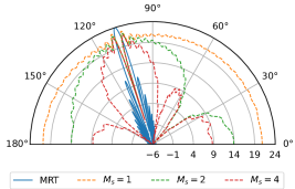
Utilizing this methodology, the absolute distortion level, found in (2), is calculated at all observer locations. This is done at an input back-off of and the number of saturated antennas for the Z3RO precoder is set to two (). As seen in Fig. 1, the distortion at the user location is reduced for the Z3RO precoder, which is to be expected given that the Z3RO precoder nulls the third-order distortion term at the user location. Additionally, the distortion is spread out spatially, which results in higher distortion values for the Z3RO precoder at the observer locations. This is consistent with the theoretical results obtained in [9], as can be seen in Fig. 2. The results illustrated in Fig. 1 solely depict one possible user location. However, given the 42 measurement locations, it is possible to place the user once at all of these 42 locations. For a thorough comparison of both precoders, the empirical cumulative distribution function (eCDF) when placing the user at every possible location is shown in Fig. 4(a). This shows that the distortion level at the user location for the Z3RO precoder is significantly lower than for the MRT precoder. On average, the Z3RO precoder reduces the distortion at the user location by . We can also observe that the overall distortion power for the Z3RO precoder is slightly higher compared to the MRT precoder at the unintended locations, i.e., the observer positions, confirming the theoretical behaviour as derived in [9]. Furthermore, it also demonstrates that the worst-case scenario is avoided, i.e., for high distortion levels the Z3RO precoding results in less distortion than MRT. Besides the absolute distortion level, the symbol rate () is also considered. Fig. 3 shows the symbol rate when the noise variance () is varied, given a constant . As can be seen in Fig. 3, if the system is noise limited (i.e., )222Note that represents the squared L2-norm of the channel., MRT shows a slightly larger symbol rate. However, when the system is distortion limited (i.e., ), the Z3RO precoder has a higher symbol rate. This confirms and validates the intended behaviour of the Z3RO precoder, as it improves performance when the system is distortion limited.
[width=0.8]fig/location_A6
[width=0.9]fig/single_user_cdf
[width=0.9]fig/cdf_2user_correct
III-C Two-User Case
For the two-user case the number of saturated antennas is now equal to four (). We define the user location index of user as . Both users use the same time and frequency resources. The same reasoning used in the single-user case can be followed for the multi-user case. The signal, intended for user , received at observer can be described as,
| (4) |
where , . Note that now also includes inter-user interference. The Bussgang gain is computed as [13]. The variance of the distortion and inter-user interference can be determined by,
| (5) |
The SNIDR at user is then given by
| (6) |
Equivalently to the single-user case, a lower bound on the achievable rate for the multi-user case can be obtained as follows,
| (7) |
The only difference in the multi-user case is that the achievable rate is also impacted by the inter-user interference.
Utilizing equation (5), Fig. 4(b) depicts the eCDF of the distortion level (now including the inter-user interference) when considering every possible two-user combination given the 42 measurement locations. This figure shows an average reduction of the distortion power at the user locations of . The worst-case scenario, in terms of absolute distortion power, is also here reduced by for Z3RO precoding. This demonstrates the ability of the Z3RO precoder to reduce the distortion level at the user location, even in the two-user case. We note that the distortion reduction is smaller than in the single-user case. However, this is to be expected given that the two-user case is less stringent as the distortion is more spatially spread out when more users are present.
IV Conclusion
In this study, the performance of the Z3RO precoder was assessed based on real-world channel measurements. The results demonstrate an average distortion reduction at the user location of in the most stringent single-user case and in the two-user case. Additionally, we showed that the lower-bound symbol rate for the Z3RO precoder is better as compared to MRT, when the system is distortion limited. Finally, we confirmed that the Z3RO precoder introduces slightly more distortion at the unintended locations. However, we see that the worst-case scenario is avoided, as for high distortion levels, the Z3RO precoded signals experience less distortion than MRT, in the single-user case and in the two-user case. This assessment validates the capability of the Z3RO precoder to operate massive MIMO systems closer to the saturation of the PAs and hence increase the energy efficiency considerably. In this study, promising results with respect to distortion mitigation were found for the single and two-user cases. However, currently no inter-user interference cancelation is present in the Z3RO precoder, making it challenging to deploy the precoder to scenarios with more users. Future research should aim to address this limitation.
References
- [1] G. Auer, V. Giannini, C. Desset, I. Godor, P. Skillermark, M. Olsson, M. A. Imran, D. Sabella, M. J. Gonzalez, O. Blume, and A. Fehske, “How much energy is needed to run a wireless network?” IEEE wireless communications, vol. 18, no. 5, pp. 40–49, 2011.
- [2] S. Cripps, RF Power Amplifiers for Wireless Communications, ser. Artech House Microwave Library. Norwood: Artech House, 2006.
- [3] E. G. Larsson and L. Van Der Perre, “Out-of-Band Radiation From Antenna Arrays Clarified,” IEEE wireless communications letters, vol. 7, no. 4, pp. 610–613, 2018.
- [4] C. Mollen, U. Gustavsson, T. Eriksson, and E. G. Larsson, “Spatial Characteristics of Distortion Radiated From Antenna Arrays With Transceiver Nonlinearities,” IEEE transactions on wireless communications, vol. 17, no. 10, pp. 6663–6679, 2018.
- [5] C. Studer and E. G. Larsson, “PAR-Aware Large-Scale Multi-User MIMO-OFDM Downlink,” IEEE journal on selected areas in communications, vol. 31, no. 2, pp. 303–313, 2013.
- [6] S. R. Aghdam, S. Jacobsson, U. Gustavsson, G. Durisi, C. Studer, and T. Eriksson, “Distortion-Aware Linear Precoding for Massive MIMO Downlink Systems with Nonlinear Power Amplifiers,” 2020.
- [7] I. Iofedov and D. Wulich, “Distortion cancellation precoding for OFDM-SDMA downlink with nonlinear power amplifiers,” in 2015 IEEE 26th Annual International Symposium on Personal, Indoor, and Mobile Radio Communications (PIMRC). IEEE, 2015, pp. 704–709.
- [8] R. Zayani, H. Shaiek, and D. Roviras, “Efficient Precoding for Massive MIMO Downlink Under PA Nonlinearities,” IEEE communications letters, vol. 23, no. 9, pp. 1611–1615, 2019.
- [9] F. Rottenberg, G. Callebaut, and L. Van der Perre, “Z3RO Precoder Canceling Nonlinear Power Amplifier Distortion in Large Array Systems,” arXiv preprint arXiv:2110.07891, 2021.
- [10] G. Callebaut, S. Gunnarsson, A. P. Guevara, F. Tufvesson, S. Pollin, L. Van der Perre, and A. J. Johansson, “Massive MIMO goes Sub-GHz: Implementation and Experimental Exploration for LPWANs,” in 2020 54th Asilomar Conference on Signals, Systems, and Computers, 2020, pp. 1101–1105.
- [11] C. Rapp, “Effects of HPA-Nonlinearity on a 4-DPSK/OFDM-Signal for a Digital Sound Broadcasting System.” in Second European Conf. on Sat. Comm., 22. - 24.10.91, Liege, Belgium., 1991, pp. 179–184, lIDO-Berichtsjahr=1991, pages=6,.
- [12] J. J. Bussgang, “Crosscorrelation functions of amplitude-distorted Gaussian signals,” Tech. Rep. 216, Research Lab. Electron, 1952.
- [13] O. T. Demir and E. Bjornson, “The Bussgang Decomposition of Nonlinear Systems: Basic Theory and MIMO Extensions [Lecture Notes],” IEEE Signal Processing Magazine, vol. 38, no. 1, pp. 131–136, 2021.