Coded Caching for Two-Dimensional Multi-Access Networks ††thanks: M. Zhang and M. Cheng are with Guangxi Key Lab of Multi-source Information Mining Security, Guangxi Normal University, Guilin 541004, China (e-mail: ztw_07@foxmail.com, chengqinshi@hotmail.com). ††thanks: K. Wan and G. Caire are with the Electrical Engineering and Computer Science Department, Technische Universität Berlin, 10587 Berlin, Germany (e-mail: kai.wan@tu-berlin.de, caire@tu-berlin.de). The work of K. Wan and G. Caire was partially funded by the European Research Council under the ERC Advanced Grant N. 789190, CARENET.
Abstract
This paper studies a novel multi-access coded caching (MACC) model in the two-dimensional (2D) topology, which is a generalization of the one-dimensional (1D) MACC model proposed by Hachem et al. The 2D MACC model is formed by a server containing files, cache-nodes with files located at a grid with rows and columns, and cache-less users where each user is connected to nearby cache-nodes. The server is connected to the users through an error-free shared link, while the users can retrieve the cached content of the connected cache-nodes without cost. Our objective is to minimize the worst-case transmission load over all possible users’ demands. In this paper, we first propose a grouping scheme for the case where and are divisible by . By partitioning the cache-nodes and users into groups such that no two users in the same group share any cache-node, we use the shared-link coded caching scheme proposed by Maddah-Ali and Niesen for each group. Then for any model parameters satisfying , we propose a transformation approach which constructs a 2D MACC scheme from two classes of 1D MACC schemes in vertical and horizontal projections, respectively. As a result, we can construct 2D MACC schemes that achieve maximum local caching gain and improved coded caching gain, compared to the baseline scheme by a direct extension from 1D MACC schemes.
Index Terms:
Coded caching, multi-access coded caching, two-dimensional (2D) network, placement delivery array (PDA).I Introduction
Caching techniques have a central role in future communication systems and wireless cellular networks[1]. In the caching paradigm, some content is locally stored into the users’ local caches during off-peak times. Then the pre-stored content is leveraged to reduce the network congestion during peak times, such that some local caching gain arises. In the seminal paper [2], Maddah-Ali and Niesen (MN) proposed a coded caching scheme which achieves an additional multicast gain on top of the conventional local caching gain. In the MN coded caching model, a single server with file is connected to users over an error-free shared link, while each user has a local cache of size . A coded caching scheme consists of two phases: i) placement phase: some packets of each file are placed into the cache of each user without knowledge of the user’s future demand; ii) delivery phase: each user requests one file. According to the users’ demands and cache content, the server sends coded packets such that each user’s demand is satisfied. The goal is to minimize the worst-case number of transmitted packets normalized by the file size (referred to as load in this paper).
The MN coded caching scheme utilizes an uncoded combinatorial cache construction in the placement phase and linear coding in the delivery phase. When with , the achieved load is . The term in the numerator is the local caching gain, which is defined as the average fraction of each file not available in the cache of each user. The term in the denominator is the coded caching gain, which is defined as the average number of users served by one multicast message. For other memory sizes, the lower convex envelope of the above memory-load tradeoff can be achieved by memory-sharing. The load of the MN coded caching scheme was proved to be optimal within a factor of [3] and exactly optimal under the constraint of uncoded cache placement [4, 5] (i.e., each user directly copies some packets of files in its cache).
However, the MN scheme requires a subpacketization exponential to the number of users . In order to reduce the subpacketization, the authors in [6] proposed a combinatorial structure to characterize the placement and delivery strategies in a single array, referred to as Placement Delivery Array (PDA). It was shown in [7] that the schemes in [2, 6, 7, 8, 9, 10, 11, 12] can be represented by appropriate PDAs. Particularly, the PDA characterizing the MN scheme in [2] is referred to as MN PDA. Given any PDA, we can obtain a shared-link coded caching scheme for users, with subpacketization , memory ratio and load . By using PDA, various coded caching schemes were constructed to reduce the subpacketization of the MN scheme, e.g., [6, 13, 14, 15, 16, 17, 11, 9, 18, 19, 20, 21].
I-A One-Dimension Multi-access Caching
Most works on coded caching consider that each user has its own dedicated cache. Edge caching, which stores the Internet-based content at the wireless edges, boosts the spatial and spectral efficiency. The main advantages of edge caching compared to the end-user caches include that the edge nodes normally have larger storage sizes and could be accessed by multiple local users with high data rates. Such a scenario motivated the work in [22] which introduced a multi-access coded caching (MACC) problem, referred to as one-dimensional (1D) MACC problem. Different from the MN coded caching problem, there are cache-nodes with the cache size of files, while each of the users is cache-less and can access neighboring cache-nodes in a cyclic wrap-around fashion. Thus, each cache-node serves exactly users. As assumed in [22], the cache-nodes are accessed by the connected users with negligible load cost.
Under the 1D MACC model, various schemes were proposed in [22, 23, 24, 25, 26, 27, 28, 29, 30, 31, 32, 33, 34]. The most related work to this paper is our previous work in [18], which proposed a transformation approach to extend any PDA for the shared-link coded caching system (satisfying some constraints which most existing PDAs satisfy) to generate a 1D MACC scheme as illustrated in Fig. 1.

For any 1D MACC system with , by using such transformation approach on the MN PDA for shared-link coded caching scheme, we can obtain a 1D MACC caching scheme with the load .
I-B Two-Dimensional Multi-access Caching
The aforementioned works on the MACC problem only considered the 1D topology. However, in a practical cellular network, the cache-nodes are most typically placed in a two-dimensional (2D) topology to cover a plane area, such as triangle, square, and hexagon cellular geometries[35]. Motivated by this, we consider an ideal MACC problem with 2D square topology, referred to as 2D MACC. In this paper, we focus on the 2D MACC system as illustrated in Fig. 2. In this setting, cache-nodes with cache size of files are placed in a rectangular grid with rows and columns, and cache-less users are placed regularly on the same grid such that each user is in the proximity of a square of neighboring cache-nodes (where distance is defined in a cyclic wrap-around fashion).
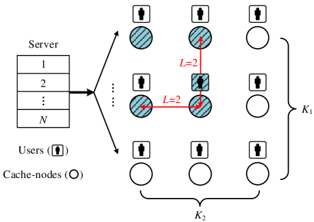
For instance, when and , the user at row and column can access the cache-nodes which are located at (row, column), , and (as illustrated in Fig. 2). Without loss of generality, we assume that . When , the 2D MACC system reduces to 1D MACC system. Similar to the 1D MACC model, users can access their cache-nodes at no cost (this assumes very fast off-load side links between users and cache-nodes). The objective of the problem is to minimize the worst-case load of the broadcast transmissions from the server to users over all possible demands.
I-C Contribution and Paper Organization
Our contributions for the new 2D MACC system are as follows.
-
•
We first propose a baseline scheme, by using an MDS precoding on each file such that the 2D MACC problem is divided into separate 1D MACC problems, each of which has cache-nodes and users. The baseline scheme achieves the maximum local caching gain and a coded caching gain equals to .
-
•
When and are divisible by , we propose a grouping scheme which partitions all the cache-nodes and users into groups such that any two users in the same group cannot access the same cache-node, and uses the MN caching scheme for each group. The grouping scheme achieves the maximum local caching gain and a coded caching gain which equals to .
-
•
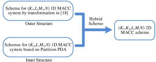
Our major contribution on this new model is to propose a new transformation approach for the case , which constructs a hybrid 2D MACC scheme (i.e., consisting of an outer structure and an inner structure) from two classes of 1D MACC schemes as illustrated in Fig. 3. In the vertical projection of the 2D system which reduces to the 1D MACC system, we select a 1D MACC scheme as outer structure from any 1D MACC scheme, which is generated by the transformation approach[18]. In the horizontal projection of the 2D system which reduces to the 1D MACC system, we use 1D MACC schemes as inner code, which are generated by using the transformation approach[18] on the Partition PDA in [15] for the shared-link caching model. Finally, by incorporating the outer and inner structures, we obtain a hybrid 2D MACC scheme, where . The grouping scheme achieves the maximum local caching gain and a coded caching gain no less than while the outer structure is generated based on the MN PDA.
The rest of this paper is organized as follows. Section II reviews some related results on the original shared-link coded caching model and 1D MACC model. Section III formulates the novel 2D MACC model. Section IV lists the main results of the paper. Sections V and VI provide the detailed constructions of the proposed caching schemes. Finally, we conclude the paper in Section VII and some proofs are provided in the Appendices.
Notations
In this paper, we use the following notations unless otherwise stated.
-
•
Bold capital letter, bold lower case letter and curlicue font will be used to denote array, vector and set respectively. The element of a set represents the smallest element in this set. is used to represent the cardinality of a set or the length of a vector;
-
•
For any positive integers , , with and , non-negative set , and vector ,
-
–
, , and , i.e., is the collection of all -sized subsets of ;
-
–
denotes the least non-negative residue of modulo .
-
–
-
–
.
-
–
represents the smallest element of , where . Assuming that , we use to represent the order of in , i.e., if and only if for any . is the entry of for each ;
-
–
.
-
–
For any array with dimension , represents the element located at the row and the column of .
-
–
The matrix is written in a Matlab form, representing .
-
–
II Preliminary Results on Original Coded Caching Model and 1D Multi-Access Coded Caching Model
In this section, we review the original shared-link coded caching model in [2] and the PDA structure in [6, 15]. Then we review the 1D MACC model in [22] and the transformation approach in [18] which constructs 1D MACC schemes from PDAs.
II-A Original Shared-link Coded Caching Model
In the original coded caching model [2], referred to as shared-link coded caching model, a server containing equal-length files, , connects through an error-free shared link to users , , , with . Each user has a cache with size of files where . An -division coded caching scheme contains two phases.
-
•
Placement phase: The server divides each file into packets with equal size, i.e., , then directly places up to packets to each user’s cache. Note that in this phase the server has no information of the users’ later demands. Define as the cache content of user .
-
•
Delivery phase: Each user randomly requests one file from the server. Assume that the demand vector is , i.e., user requests , where and . According to the users’ cache content and demand vector, the server broadcasts coded packets to the users such that each user can decode its desired file.
The objective is to minimize the worst-case load among all possible requests, defined as
| (1) |
The authors in [6] proposed a combinatorial coded caching structure, referred to as placement delivery array (PDA).
Definition 1.
([6]) For any positive integers , , and , an array composed of a specific symbol and integers in , is called a PDA if it satisfies the following conditions,
The symbol appears times in each column;
Each integer in occurs at least once in the array;
For any two distinct entries and , if , then , i.e., the corresponding sub-array formed by rows and columns must be one of the following form
Notice that, for the sake of ease notation, sometimes we also express the non-star entries in a PDA by sets or vectors rather than integers.
Based on a PDA, an -division coded caching scheme for the coded caching system can be obtained in the following way.
-
•
The columns represent the user indices while the rows represent the packet indices.
-
•
If , user caches the packet of all files. So, Condition C1 of Definition 1 implies that all users have the same memory ratio .
-
•
If is an integer , the packet of each file is not stored by user . Then the server transmits a multicast message (i.e., the XOR of all the requested packets indicated by ) to the users at time slot . Condition C3 of Definition 1 guarantees that each user can recover its requested packets since it has cached all the other packets in the multicast message except its requested one. The occurrence number of integer in , denoted by , is the coded caching gain at time slot , meaning that the coded packet is broadcasted at the time slot and simultaneously useful for users. is said to be a - PDA if for all .
-
•
Condition C2 of Definition 1 implies that the number of multicast messages transmitted by the server is ; thus the load is .
Example 1.
We use the following -- PDA to construct a coded caching scheme for the shared-link coded caching model.
-
•
Placement Phase: The server divides each file into equal-size packets, i.e., , . The users cache the following packets,
-
•
Delivery Phase: Assume that the request vector is . The server sends to the users. Then each user can recover its requested file. For instance, user requests the file and has cached , , so it can recover . The load is .
For what said above, it follows that any PDA corresponds to a coded caching scheme achieving the performance state in the following lemma.
Lemma 1.
([6]) Given a PDA, there exists an -division coded caching scheme with the memory ratio and load .
The authors in [6] showed that the seminal coded caching scheme proposed in [2] can be represented by a special PDA, referred to as MN PDA.
Construction 1.
(MN PDA [6]) For any integer , we have a - PDA, with dimension , where and , by111Notice that the rows are indexed by all the subsets , and the columns are indexed by all the integers .
| (5) |
When and , the - MN PDA is exactly the PDA in Example 1.
In order to further reduce the subpacketization of the MN PDA, the authors in [15] proposed a particular PDA construction, referred to as Partition PDA. For the sake of clarity, we express the non-star entries by vectors first.
Construction 2.
(Partition PDA [15]) For any positive integers , and where , we define the row index set as , and the column index set as . Then we have arrays , , , each of which is a array. For each , each entry in is defined as
| (8) |
where and represent the row and column indices, respectively, and represents the set of columns filled by “*” in row . Intuitively, if , the entry is a non-star entry represented by a vector with length , which is generated by replacing the coordinate of by and appending at the end of the vector.
The block array formed by stacking for all next to each other as is an - PDA.
For the sake of future convenience, we replace the vectors in by integers in according to an arbitrary one-to-one mapping ; the resulting array containing stars and integers is defined as , which is also an - PDA.
Example 2.
When , and , the Partition PDA is illustrated in Fig 4, including two sub-arrays and with dimension .
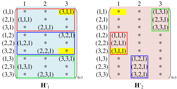
In , let us focus on the row with index ,
-
•
we have . Thus the stars are located at column and column of this row, i.e., ;
-
•
for column of this row (i.e., when ), we have from (8).
In , let us focus on the row with index ,
-
•
we have . Thus the stars are located at column and column of this row, i.e., ;
-
•
for column of this row (i.e., when ), we have from (8).
Similarly, the other entries in and are obtained as illustrated in Fig 4. Next, we check the Condition C3 of PDA in Definition 1. For instance, let us focus on the vector . In , the vector is filled in the entry at row and column ; in , the vector is filled in the entry at row and column . In row , the entry at column of is star; in row , the entry at column of is star. Thus the sub-array containing satisfies Condition C3 of PDA in Definition 1.
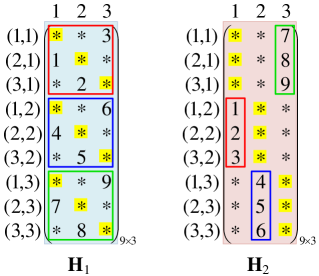
We can also replace the vectors in and by integers according to the one-to-one mapping in Table I.
The resulting arrays and are illustrated in Fig. 5.
Next, we introduce the concept of “tag-star” in a Partition PDA, which plays an important role in the constructions of this paper.
Definition 2.
For each and each , we have . Then we define this star (i.e., the star located at row and column of ) as a tag-star.
II-B 1D Multi-access Coded Caching Model
A 1D MACC system proposed in [22] contains a server with a set of equal-length files, cache-nodes, and cache-less users. Each cache-node has a memory size of files where . The cache-nodes are placed in a line, and each user can access neighboring cache-nodes in a cyclic wrap-around fashion. That is, each user , , can retrieve all the content cached by the cache-node if and only if . Each user is also connected to the server via an error-free shared link. As in [22], we assume that the users can retrieve the cache content of the connected cache-nodes without any cost. The system operates in two phases.
-
•
Placement phase: Each file is divided into packets of equal size, then each cache-node directly caches up to packets of files. Each user can retrieve the content stored at its accessible cache-nodes. The placement phase is done without knowledge of later requests.
-
•
Delivery phase: Each user randomly requests one file. According to the request vector and the retrieved content by users, the server transmits multicast messages to users, such that each user’s request can be satisfied.
Let . A transformation approach to generate a 1D MACC scheme was proposed in [18] which extends any PDA for the shared-link coded caching system satisfying , Conditions C-C in Definition 1 and Conditions C, C (which will be clarified soon).
First, satisfies the following condition,
-
•
C4. Each row of has exactly stars.
Then we define
| (9) |
as column index set of star entries in row of . Notice that since each packet is cached times in the original MN caching model.
In 1D MACC scheme, each file is divided into equal-length subfiles, where , and the caching procedure is also divided into rounds. For any , in the round we only deal with the subfile of each file. Furthermore, it is sufficient to introduce the construction in the first round since all the caching procedures in different rounds are symmetric. In the first round, the authors in [18] showed that the node-placement array , user-retrieve array , and user-delivery array are generated by the PDA as follows.
-
•
Node-placement array . In order to obtain the maximum local caching gain, the scheme guarantees that any neighboring cache-nodes do not cache any common packets. Thus based on , the node-placement array is defined as
(12) where
(13) Here represents the set of cache-nodes caching the packet indexed by . From (13), there are stars in each row, which means that each packet stored by cache-nodes. Moreover, any two entries and in satisfy ,222Recall that where . which means that any two cache-nodes accessed by the same users do not cache common packets.
-
•
User-retrieve array . According to the relationship between users and their accessible cache-nodes, based on , the user-retrieve array is defined as
(16) where
(17) Here represents the set of users who can retrieve the packet indexed by . From (13) and (17), there are stars in each row, which means that each packet can be retrieved by users. In addition, for any row indexed by , we can divide the starts into groups and each group has consecutive stars, where the group is defined as
(18) represents the set of users who retrieve the packet cached by cache-node .
Another important observation is that, each packet cannot be retrieved by users, which is exactly the same as the number of users not caching each packet in the original PDA .
-
•
User-delivery array . Based on and , the user-delivery array is defined as
(21) where . is a one-to-one mapping from (i.e., the column index set of where the entries in row are non-star) to (i.e., the column index set of original PDA where the entries in row are non-star). So,
(22) Hence, the alphabet set of the resulting contains different integers which indicate the broadcasted messages.
Remark 1.
In [18], the authors showed that in order to guarantee satisfying Condition C3, the original PDA should satisfy,
-
•
C. For any two distinct entries and satisfying , assume that , , we have and for some integers .
It turns out that most existing PDAs meet Conditions C4 and C5, such as MN PDA and the PDAs in [6, 15, 9, 11].
After determining , and , the placement and delivery strategies of 1D MACC scheme are obtained in the first round. For each , in the round, we only need to cyclically right-shift , , and by positions, respectively. For the total placement array of cache-nodes, there are stars in each column, while this array has rows. Hence, each cache-node caches files, satisfying the memory size constraint.
In conclusion, by the above transformation approach, we obtain the following theorem.
Theorem 1.
([18]) Given any PDA satisfying Conditions C-C, there exists a 1D MACC scheme where , with the transmission load .
By applying the transformation approach into the MN PDA, a 1D MACC scheme can be obtained as follows, referred to as CWLZC 1D MACC scheme.
Corollary 1.
(CWLZC 1D MACC scheme) Given a MN PDA , there exists a 1D MACC scheme for 1D MACC system where , with the transmission load
Example 3.
We consider a 1D MACC scheme based on the MN PDA . The construction of node-placement array , user-retrieve array , and user-delivery array in the first round is illustrated in Fig. 6.
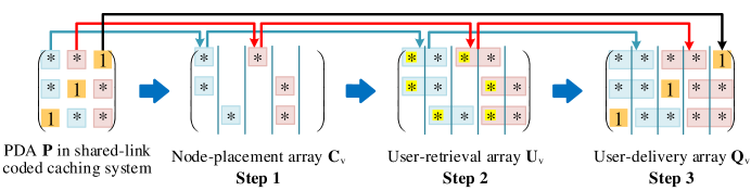
-
•
The node-placement array is constructed from . More precisely, in row , the stars at columns and of are corresponded to columns and of , respectively; in row , the stars at columns and of are corresponded to columns and of , respectively; in row , the stars at columns and of are corresponded to columns and of , respectively. By this construction, any two cache-nodes connected to the same users do not cache any common packets.
-
•
The user-retrieve array is constructed from by the relationship between users and the accessible cache-nodes. More precisely, in row , the first star at column of is extended to the stars at columns and in the first group of , the second star at column of is extended to the stars at columns and in the second group of ; in row , the first star at column of is extended to the stars at columns and in the first group of , the second star at column of is extended to the stars at columns and in the second group of ; in row , the first star at column of is extended to the stars at columns and in the first group of , the second star at column of is extended to the stars at columns and in the second group of . Thus each packet can be retrieved by users.
-
•
The user-delivery array is constructed by filling the non-star entries in according to the integers in . More precisely, in row , the integer “” at column of is filled at column of ; in row , the integer “” at column of is filled at column of ; in row , the integer “” at column of is filled at column of .
After determining , , and , we have the placement and delivery strategies for the 1D MACC system in the first round. Assume that the request vector is , the server sends to the users. Then the overall transmission load is which coincides with Corollary 1.
Another class of useful 1D MACC schemes for this paper are generated by using the transformation approach [18] on the Partition PDA proposed in [15].
Corollary 2.
(1D MACC scheme based on Partition PDA) Given a - Partition PDA , there exists different 1D MACC schemes for 1D MACC system. The overall transmission load for schemes is .
Example 4.
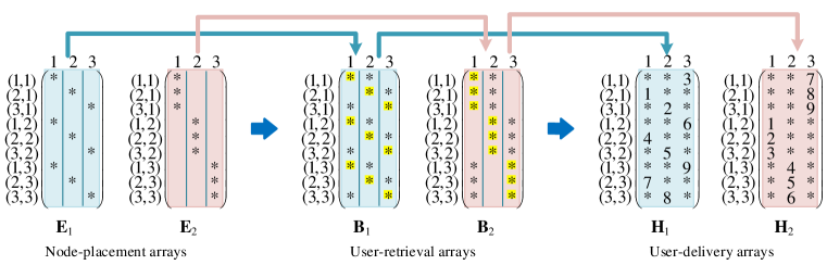
We consider two different 1D MACC schemes generated by using the transformation approach on - Partition PDA . The node-placement arrays , , user-retrieve arrays , , and user-delivery arrays , are illustrated in Fig. 7.
-
•
The node-placement arrays , consist of the tag-stars (defined in Definition 2) in sub-Partition arrays , . Recall that, the row indices exactly indicate the positions of tag-stars where the first coordinate corresponds to the column index of stars in ; the second coordinate corresponds to the column index of stars in .
-
•
The user-retrieve arrays , are constructed from , by the relationship between users and the accessible cache-nodes. More preciously, , are generated by extending each star in , to stars. For instance, in the row indexed by , the star at column of is extended to the stars at columns and of ; the star at column of is extended to the stars at columns and of . Notice that, , have the same star entries as , of Partition PDA in Example 2.
-
•
The user-delivery arrays , are constructed by filling the non-star entries in , . Since , have the same star entries as sub-Partition PDAs , in Fig 5, , are used to be user-delivery arrays.
III System Model: 2D Multi-access Coded Caching Model
The new 2D MACC model considered in this paper, with parameters , is given as follows. A server containing equal-length files is connected to cache-less users through an error-free shared link. Without loss of generality, we assume that . There are also cache-nodes, each of which has a memory size of files where . The cache-nodes are placed in a array (see Fig. 2), and at the position of each cache-node there is one user. For any positive integers and , the cache-node and the user located at row and column of the array, are denoted by and , respectively. Each user can retrieve all the content cached by the cache-node , if and only if the modular distances and are less than , i.e.,
| (23) |
Each user is connected to neighboring cache-nodes in a cyclic wrap-around fashion. For instance, in Fig. 2 user can access neighboring cache-nodes , , , . Similar with 1D MACC model, we assume that the users can retrieve the cache content of the connected cache-nodes without any cost. A 2D MACC scheme consists of two phases,
-
•
Placement phase: The server divides each file into packets with equal size. For any positive integers and , cache-node caches up to packets of files. Each user can retrieve the packets stored by its connected cache-nodes. This phase is done without knowledge of later requests.
-
•
Delivery phase: For any request vector representing that user requests file where and , the server transmits coded packets to users such that each user can decode its requested file.
Notice that, each column (or row) in the 2D MACC model is exactly a 1D MACC model in Section II-B. The objective of the 2D MACC problem is to minimize the worst-case load , as defined in (1).
IV Main Results
In this section, our new schemes for the 2D MACC network are presented. We first provide a baseline scheme by directly extending the CWLZC 1D MACC scheme. Then, when and , we improve the baseline scheme by a grouping scheme. Next, for the more general case where (i.e., ), we propose a new transformation approach, which constructs a hybrid 2D MACC scheme from two classes of 1D MACC schemes. Thus, concatenating the new transformation approach with the transformation approach from PDAs to 1D MACC schemes proposed in [18], we obtain a transformation approach from PDAs to 2D MACC schemes. Finally, the performance analysis and construction examples of these two schemes are introduced.
IV-A Proposed 2D MACC Schemes
By directly using the CWLZC 1D MACC scheme in Corollary 1 into the 2D model, we obtain the following baseline scheme.
Theorem 2.
(Baseline Scheme) For the 2D MACC problem, the lower convex envelope of the following memory-load tradeoff corner points is achievable,
-
•
when ,
(24) and ;
-
•
when ,
(25) where , and .
Proof.
Assume that in a 2D MACC system, each file has packets where and divide , and each packet has enough bits such that any field extension can be operated. The 2D topology can be divided into columns, such that each column can be regarded as a 1D MACC system with cache-nodes and users, where each user can access neighboring cache-nodes.
We first consider the case .
-
•
Placement Phase. We divide each file into subfiles with equal length, i.e., where . Each subfile has packets. For each integer , denote the set of all the subfiles by . Then, the server places into the cache-nodes in the column by using the placement strategy of CWLZC 1D MACC scheme in Corollary 1. Each cache-node totally caches packets.
-
•
Delivery Phase. Given any demand vector , the server sends the coded subfiles of to the users in the column by using the delivery strategy of CWLZC 1D MACC scheme, for each . Since the server uses the delivery strategy of CWLZC scheme exactly times, from Corollary 1, the transmission load is
where .
-
•
Decodability. In the 2D MACC system, each user can access all the cache-nodes in each row which cache different subfiles. Hence, each user can totally obtain subfiles of each file from the placement and delivery phases, such that it can decode its desired file.
Similar to the above case, the scheme for the case can be obtained as follows. In the placement phase, each file where is divided into non-overlapping and equal-length subfiles, which are then encoded into subfiles by a MDS code, i.e., . Each MDS-coded subfile has packets. The server places to the cache-nodes in the column by using the CWLZC 1D MACC scheme. Each cache-node caches packets, satisfying the memory size constraint. In the delivery phase, for each , the server sends the required subfiles of to the users in each column by using the CWLZC 1D MACC scheme. Since the server uses the delivery strategy of CWLZC scheme exactly times, the transmission load is
where and . In the 2D MACC system, each user can retrieve different subfiles which are stored in neighboring cache-nodes in each row. By the property of MDS code, each file could be recovered from any of its subfiles; thus the demand of each user is satisfied. ∎
Note that, when the coded caching gain of the scheme in Theorem 2 is always less than . To improve this scheme, when and , we can divide the cache-nodes into non-overlapping groups, each of which has cache-nodes. By using the MN scheme for each group, we have the following scheme whose coded caching gain is , whose proof could be found in Section V.
Theorem 3.
(Grouping Scheme) For the MACC problem, when and , the lower convex envelope of the following memory-load tradeoff corner points is achievable,
| (26) |
Next, we will propose a highly non-trivial hybrid construction for the case . This construction is consisted of outer and inner structures, which is built on a transformation approach from two classes of 1D MACC schemes (for 1D MACC systems in vertical and horizontal projections of the 2D MACC system, respectively) to a 2D MACC scheme. As the outer structure (i.e., the vertical projection of 2D system), we could choose any 1D MACC scheme from the transformation approach in Theorem 1. As the inner structure (i.e., the horizontal projection of 2D system), we choose different 1D MACC schemes from the transformation approach on Partition PDA in Corollary 2.
Theorem 4.
(Hybrid Scheme) For the MACC problem with , given any PDA (satisfying Conditions C-C) where , and a - Partition PDA, the lower convex envelope of the following memory-load tradeoff corner points is achievable,
| (27) |
and , .
When the 1D MACC scheme for the outer structure is generated from the MN PDA in Corollary 1, by applying the novel transformation approach in Theorem 4, the following result can be directly obtained.
Theorem 5.
(Hybrid Scheme via MN PDA) For the MACC problem with , given a - MN PDA where , and a - Partition PDA, the lower convex envelope of the following memory-load tradeoff corner points is achievable,
| (28) |
and , .
Remark 2.
(Local caching gain and coded caching gain in Theorem 5) The local caching gain of the hybrid scheme in Theorem 5 is , which is the same as the local caching gains of the baseline scheme and the grouping scheme in Theorems 2 and 3. In addition, its coded caching gain is between (the denominator of the first item) and (the denominator of the last item).
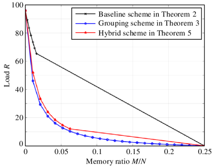
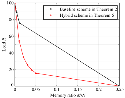
We conclude this subsection with some numerical comparisons of the schemes in Theorems 2, 3, and 5. In Fig 8(a), we consider the case where , , , and . It can be seen that both schemes in Theorems 3 and 5 have lower loads than the baseline scheme in Theorem 2. Furthermore, the load of the hybrid scheme in Theorem 5 is slightly larger than that of the grouping scheme in Theorem 3. In Fig. 8(b), we consider the case where , , , and . Since does not divide nor , the scheme in Theorem 3 cannot be used. It can be seen that the proposed hybrid scheme in Theorem 5 outperforms the baseline scheme in Theorem 2.
IV-B Example of the Grouping Scheme in Theorem 3
Let us consider a 2D MACC problem. In this case, we have and .
-
•
Placement phase. Each file is divided into subfiles with equal length, i.e., where , and the cache-nodes are divided into groups, i.e.,
as illustrated in Fig 9.
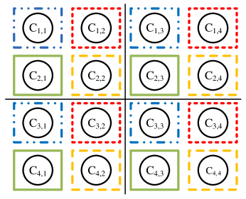
Figure 9: Groups of cache-nodes in the grouping scheme. Then the server places the subfiles to the cache-nodes in , , by the placement phase of MN scheme. Each cache-node caches file, satisfying the memory size constraint. Furthermore, any two cache-nodes connected to the common user do not cache the same content. Since each user can access cache-nodes, the local caching gain of the proposed scheme is . In each group, every user can retrieve one different subfile of each file.
-
•
Delivery phase. We divide the users into the following four groups according to the cache-node groups,
Let us focus on the group of users, where . The transmission for this group of users contains time slots. In the time slot where , these users will use the cache content of the cache-nodes in . The multicast messages in this time slot are generated through the MN scheme on the subfiles in which are demanded by the users in .
Since the coded caching gain of the MN scheme is , the load of the proposed scheme is , which coincides with (26).
IV-C Example of Hybrid Scheme in Theorem 5
Let us consider the 2D MACC system. The hybrid scheme in Theorem 5 consists of an outer structure and an inner structure, which are generated from a scheme for the 1D MACC problem (i.e., the 1D model in the vertical projection of the 2D model), and schemes for the 1D MACC problem (i.e., the 1D model in the horizontal projection of the 2D model), respectively. We choose these two classes of 1D MACC problems satisfying .
We divide each file into equal-length subfiles, , and divide the caching procedure into separate rounds. For each , in the round we only consider the subfile of each file. Since all the caching procedures in different rounds are symmetric, we focus on the first round, and construct the node-placement array , user-retrieve array and user-delivery array , defined as follows.
Definition 3.
Given integers and which represent the subpacketization of the first round and the number of cache-nodes (or users) respectively, we define that
-
•
An node-placement array consists of “” and null entries. The entry located at the position in is star if and only if the cache-node caches the packet of where . Note that, the cache-nodes are ordered into columns of as .
-
•
An user-retrieve array consists of “” and null entries. The entry located at the position in is star if and only if the user can retrieve the packet of where , from its connected cache-nodes. Note that, the users are ordered into columns of as .
-
•
An user-delivery array consists of , which is obtained by filling the null entries in by some integers. Each integer represents a multicast message, while represents the total number of multicast messages transmitted in the first round during the delivery phase.
For the sake of clarity, we label the columns of , and by vectors where and . For each , we define as the column index set . The constructions of , and are listed as follows, as illustrated in Fig. 10.
-
•
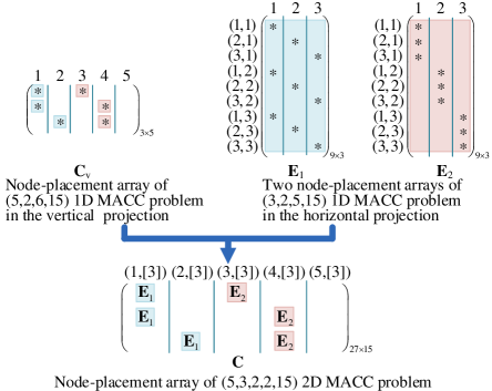
The construction of node-placement array . As illustrated in Fig. 10(a), the node-placement array is designed via outer and inner structures, respectively. is composed of an outer structure which corresponds to a vertical 1D MACC problem containing cache-nodes. We select the node-placement array of the 1D MACC scheme (detailed in Fig. 6 ) as the outer structure. We then extend into the 2D MACC node-placement array by replacing each entry in by an inner node-placement array with columns. More precisely:
-
–
For the stars in each row of , we replace the first star by , and replace the last star by . Note that, the inner structure and are node-placement arrays (detailed in Fig. 7) of the 1D MACC problem in the horizontal projection of the 2D model.
-
–
For the null entry in each row of , we replace it by a null array with dimension which is the same as and .
By this construction of , any two cache-nodes connected to common users do not cache any common packets. In other words, for each row of (representing each packet), any two stars at column and column satisfying .333We define that .
-
–
-
•
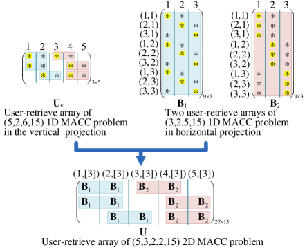
The construction of user-retrieve array . Once the node-placement array is designed, the user-retrieve array is also determined, as illustrated in Fig. 10(b). In the 2D MACC system, each user can access cache-nodes satisfying (23). In other words, focus on the same row of and , if the column in is “*”, then the column in is set to be “*” where and . From the design of , the outer structure of corresponds to the user-retrieve array of the 1D MACC scheme detailed in Fig. 6. We then extend into the 2D MACC user-retrieve array by replacing each entry in by an inner user-retrieve array with columns. More precisely:
-
–
For the stars in each row of , we replace the first consecutive stars by , and replace the last consecutive stars by . Note that and are the user-delivery arrays for the inner structure detailed in Fig. 7, which are from the 1D MACC problem in the horizontal projection of the 2D model. Since there are rows of , we obtain and of , respectively.
-
–
For the null entry in each row of , we replace it by a null array with dimension .
-
–
-
•
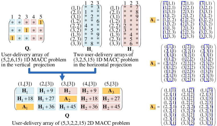
The construction of user-delivery array . is obtained by filling the null entries of such that the Condition C3 of PDA in Definition 1 is satisfied. As illustrated in Fig. 10(c), we design from in two steps:
-
–
In the first step, we fill the null entries in the inner structure of , i.e., the null entries of and . Recall that and are user-delivery arrays of the 1D MACC problem detailed in Fig. 7, which correspond to sub-Partition PDAs of in Fig. 5. We replace the 6 arrays and 6 arrays in by and for each from left to right then from top to bottom, respectively. For example, the first is replaced by and the second is replaced by , because there are different integers in .444 Recall that for any integer , denotes an array , where . Since constitutes a Partition PDA, this integer-filling is valid for the conditions of PDA. As a result, we have used integers, each of which occurs times. Hence, the coded caching gain for the multicast messages in the first step (referred to as Type I multicast messages) is .
-
–
In the second step, we fill the null entries in the outer structure of by arrays , , and , each of which has dimension . For each , we label each of entries in by a -dimensional vector , where . In , as illustrated in Fig. 10(c), the sets of column indices of , , and are , and 555Recall that for each , we define as the column index set ., respectively. In , any vector is filled in the entry indexed by row and column of . In , any vector is filled in the entry indexed by row and column of . In , any vector is filled in the entry indexed by row and column of . By the above construction, it can be checked that Condition C3 of PDA in Definition 1 is satisfied. For instance, let us focus on the case filled in , , and . The sub-array of containing the vector is denoted by . We will show that is with the form illustrated in Fig. 11, and thus satisfies Condition C3 of PDA in Definition 1. In the vector is filled in the entry indexed by row and column ; in the vector is filled in the entry indexed by row and column ; in the vector is filled in the entry indexed by row and column . By Definition 2 of the Partition PDA, the entry at row and column of is tag-star; the entry at row and column of is tag-star. Thus we obtain row of . Similarly, the entry at row and column of is tag-star; the entry at row and column of is tag-star. Thus we obtain row of . The entry at row and column of is tag-star; the entry at row and column of is tag-star. Thus we obtain row of . So the multicast message for the vector is decodable.
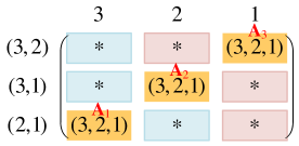
Figure 11: The sub-array containing the vector in , , . As a result, we have used vectors, each of which occurs times. Hence, the coded caching gain for the multicast messages in the second step (referred to as Type II multicast messages) is .
-
–
After determining , , and , the placement and delivery strategies are obtained during the first round. For each , in the round, we only need to right-shift , , and by positions in a cyclic wrap-around fashion. Denoting the node-placement array for the round by , the overall placement array of the cache-nodes is . Since each has stars, and each column of and has stars, the number of stars in each column of is . In addition, has rows. Thus each cache-node caches files, satisfying the memory size constraint.
According to the placement strategy, in the hybrid scheme, any two cache-nodes connected to some common users do not cache the same packets. Since each user can access cache-nodes in the 2D MACC system, the local caching gain of the proposed scheme is In the delivery phase, there are multicast messages in Type I with the coded caching gain ; there are multicast messages in Type II with the coded caching gain . So the overall coded gain of the hybrid scheme is ; thus the achieved load is , which coincides with (28).
V Proof of Theorem 3
In this section, we describe the grouping scheme for 2D MACC system under the constraints and . Cache-nodes and users are divided into the following groups respectively,
where , , , . Then .
-
•
Placement phase. Each file is divided into subfiles with equal length, i.e., . Define that for each . The server places the subfiles in to the cache-nodes in , by the placement phase of the MN scheme where . Each cache-node caches files, satisfying the memory size constraint. Furthermore, any two cache-nodes connected to the common user (i.e., satisfying (23)) do not cache the same content.
-
•
Delivery phase. Focus on the users in group , where , . The transmission for this group of users contains time slots. Each time slot is indexed by , where , . In the time slot , the users will use the cache content stored by the cache-nodes in . The multicast messages in this time slot are generated through the MN scheme on the subfiles in which are demanded by the users in . Since there are groups of users, the transmission load is
where .
-
•
Decodability. In the 2D MACC system, each user can access all the cache-nodes satisfying (23) which cache different subfiles. Hence, each user can totally obtain subfiles of each file from the placement and delivery phases, such that it can decode its desired file.
Hence, we proved the Theorem 3.
VI Proof of Theorem 4
In this section, we describe the hybrid scheme (i.e., consisting of outer and inner structures) for the 2D MACC system, where . The hybrid scheme constructs a novel transformation approach to generate 2D MACC scheme from two classes 1D MACC schemes, where the outer structure corresponds to a scheme for the 1D MACC problem in vertical projection is generated by the transformation approach proposed in [18] and detailed in Section II-B; and the inner structure corresponds to different schemes for 1D MACC problem in the horizontal projection are generated by using the transformation approach [18] on the Partition PDA in [6] for the shared-link caching model.
In the hybrid scheme, we divide each file where into subfiles with equal length, i.e., . Denote the set of the subfiles by for each . We divide the whole caching procedure into separate rounds, where in the round we only deal with . Our construction contains three steps: the generations of node-placement array , user-retrieve array , and user-delivery array , respectively.
VI-A Caching Strategy for Cache-nodes: Generation of the Array
From Section IV-C, we first construct the node-placement array of the 2D MACC system in the first round. is designed via outer and inner structures, respectively. We select the node placement array (defined in (12)) for the outer structure which corresponds to the 1D MACC problem in the vertical projection of the 2D model, and then extend into the 2D MACC node-placement array by replacing each entry in by an inner node-placement array with columns. More precisely, for the stars in each row of , we replace them (from left to right) by , each of which corresponds to a node-placement array of the 1D MACC problem in the horizontal projection of the 2D model. For null entries in , we replace each of them by a null array with dimension (i.e., with the same dimension as ), where equals to the subpacketization of Partition PDA that detailed in Section II-A. Then we get the node-placement array in the first round. By this construction, any two cache-nodes connected to some common users do not cache the same packet, since any two stars at column and column satisfying from (13).
For each , in the round, the node-placement array is generated by cyclically right-shifting by positions. In our hybrid construction, we use to represent the overall placement array of the cache-nodes. Since each outer structure has stars in each column, and each inner structure has stars in each column, the number of stars in each column of is . In addition, has rows. Thus, the memory size of each cache-node is
satisfying the memory size constraint.
Note that when , the above construction on is illustrated in Fig. 10(a).
VI-B Packets Retrievable to Users: Generation of the Array
After constructing the node-placement array , the user-retrieve array is determined, since each user can access cache-nodes satisfying that the row and column modular distances are less than . In other words, for the same row of and , if the column of is “*”, then the column of is set to be “*” where and .
From the design of , we select the user-retrieve array (defined in (16)) for the outer structure which corresponds to the 1D MACC problem in the vertical projection, then extend to the 2D MACC user-retrieve array by replacing each entry in by an inner node-placement array with columns. More precisely, focus on each row of :
-
•
There are stars in this row; as shown in Section II-B, we can divide these stars into disjoint groups, each of which has consecutive stars. For each , we replace each of the stars in the group (defined in (18)) by .666 Recall that correspond to different user-retrieve arrays of the 1D MACC problem in the horizontal projection.
-
•
For null entries in this row, we replace each of which by a null array with dimension .
Then we get the user-retrieve array in the first round. Since each outer structure has stars in each row and each inner structure has stars in each row, the number of stars in each row of is . So, there are null entries in each row of .
Remark 3.
The null entries in each row of can be divided into two disjoint parts.
-
•
Type I : The inner structure null entries, i.e., the null entries in for all of . Since there are null entries in each row of , and stars in each row of are replaced by , thus there are totally null entries in each row of in Type I.
-
•
Type II: The outer structure null entries, i.e., the null entries not in any for all of . Since there are null entries in each row of , and each of which is replaced by a null array with columns in , thus there are null entries in each row of in Type II.
For each , in the round, the user-retrieve array is obtained by cyclically right-shifting by positions.
Note that when , the above construction on is illustrated in Fig. 10(b).
VI-C Delivery Strategy: Generation of the Array
The user-delivery array is obtained by filling the null entries of such that Condition C3 of PDA in Definition 1 is satisfied. Inspired from Remark 3, we fill the null entries in two steps:
VI-C1 Step 1. Fill the null entries in Type I
From Remark 3, the entries in Type I are exactly the null entries of where . Recall that for each , the user-retrieve array has the same star entries as of Partition PDA . We fill the null entries in Type I by replacing all arrays in 777 Recall that represents the number of rows in . In each row and for each , there are exactly stars replaced by to obtain . Thus for each , there are arrays in . by 888 Recall that for any integer , denotes an array , where . (from left to right, from top to bottom) for each , where and is the number of different integers in .
For each , since constitutes a Partition PDA, this integer-filling scheme satisfies Condition C3 of Definition 1.
Remark 4.
From Fig. 10(c) and Section VI-B, the filling rule for Type I entries also can be seen as follows: for each row of (user-delivery array in vertical 1D MACC problem), we replace each of the stars in group by (user-delivery array in horizontal 1D MACC problem), since has the same star entries as , and has the same star entries as ; then increment the integers in by the occurrence orders.
From Remark 3, there are non-star entries in Type I of . From Construction 2, each integer in Type I occurs times. So there are
different integers filled in Type I of , i.e., the server sends Type I multicast messages of packets in the first round.
Example 5.
Let us return to the example in Section IV-C with , which is based on the - Partition PDA in Example 2. and are illustrated in Fig.5.
Then the following 2D MACC user-delivery array can be obtained in Table II.
More precisely, since the number of rows in is , and in each row of , there are stars replaced by , thus there are arrays in . In the first row, we fill the null entries in Type I by replacing the first of by , and replacing the second of by . In the second row, we replace the first of by , and replace the second of by . In the third row, we replace the first of by , and replace the second of by . In the similar way, we replace the arrays in . As a result, we used integers in Type I which equals .
VI-C2 Step 2. Fill the null entries in Type II
Next, we fill the outer structure null entries in Type II. Recall that our hybrid scheme is combined with two 1D MACC problems in vertical and horizontal projections. In vertical 1D MACC problem, the row index is denoted by ; and column index is denoted by . In horizontal 1D MACC problem, the row index is denoted by (same as Partition PDA detailed in Section II-A); and the column index is denoted by . Thus in the 2D MACC problem, we define the row index of and as
| (29) |
and the column index of and as
| (30) |
In addition, the following notations are useful to fill the null entries in Type II. For any integer , we assume that the integer occurs times in , i.e., . Without loss of generality, we assume that . Notice that, all these entries containing are distributed in different rows and columns by Condition C3 of Definition 1. Denote the set of columns in containing by
| (31) |
Focus on the sub-array of containing , for each , all the entries in row are stars except the entry at column since Condition C3 in Definition 1. Then we define
| (32) |
to indicate the users served by the multicast message containing and able to retrieve the packet.
From Remark 4, for each and each , we define a one-to-one mapping
| (33) |
to indicate which sub-Partition array replaces the star entry . For instance, in the last row of Table II and , we have since this entry is obtained by using . Then for each , we define
| (34) |
and
| (35) |
which indicate the subscripts of beneficial sub-Partition PDAs by the multicast message containing “” in row , and the other non-beneficial sub-Partition PDAs, respectively.
Now we are ready to introduce our filling rule for the entries in Type II. From Remark 3, the entry with index of is a Type II null entry if , where . Thus we only need to design the filling rule for these entries, as
| (36) |
where
| (37) |
which is consistent with in (21), i.e., the user-delivery array in the vertical 1D MACC problem; and
| (38) |
where satisfies that . Here, the subscripts and are given in (34) and (35), respectively.
By the above construction, the following lemmas can be obtained whose detailed proofs are given in Appendices A and B.
Lemma 2.
Lemma 3.
In the hybrid scheme, Type II entries defined by satisfying each integer occurs at least once; and each vector occurs at least once.
From Lemma 3, there are
different vectors filled in Type II of , i.e., the server sends Type II multicast messages of packets in the first round.
In conclusion, the server totally sends multicast messages in the first round during the delivery phase. Furthermore, the hybrid scheme contains rounds. With , we can compute that the transmission load of the hybrid scheme is
| (39) |
which coincides with Theorem 4.
Example 6.
We return to the Example 5. From (37) and Example 3, for the integer , we have
Thus . From (32), we have
Then combining with Example 5, (34) and (35), we have
and .
When , , , and , we consider the entry in the row indexed by and the column indexed by . Since , from (36), (37) and (38), we have
Notice that, is the third element of set , thus the vector is generated by appending into the third coordinate of the vector . Similarly, we have
The sub-array, which contains in Table III, is exactly the sub-array in Fig. 11999For convenience, we omitted the integer in Fig. 11., and satisfies Condition C3 of Definition 1.
| * | * | ||
| * | * | ||
| * | * |
VII Conclusion
In this paper, we formulated a new 2D MACC system, which is a generalization of the existing 1D MACC system. A baseline 2D MACC scheme was first proposed by directly extending 1D MACC schemes to the 2D model via an MDS precoding. When and are both divisible by , we proposed an improved scheme via a grouping method. For the case where , we propose a new transformation approach to construct a hybrid 2D MACC scheme by using two classes of 1D MACC schemes as outer and inner structures. On-going works include the derivation on the converse bounds for the 2D MACC model and the extension of the proposed schemes to more general 2D cellular networks, hierarchical networks, and combination networks.
Appendix A Proof of Lemma 2
For any two different entries in Type II, and , we have
from (36), (37) and (38). Furthermore, focus on the sub-arrays containing and . By simplifying (31) and (32), we have
where and indicate the sets of columns containing integer and , respectively; and indicate the sets of columns containing stars in row and row , respectively.
Assume that
thus we have
It was proved in [18] that user-delivery array for the outer structure satisfies Condition C3 the original PDA satisfies Condition C5 in Remark 1. Assume that satisfies Condition C5, thus . Furthermore, for some integers , we have , where and are the sets of columns containing stars in row and row of ; and , where and are the sets of columns containing stars in row and row of . Then let and . From (21), we have . From the construction of the vertical 1D MACC scheme in Section II-B, we have and for some integers . Thus and holds, i.e., . Hence, satisfies Condition C3 in Definition 1.
Now we will prove satisfies Condition C3. Since satisfies Condition C3, we have and . In the construction of the hybrid scheme in 2D MACC model, from Remark 4, these stars of are replaced based on arrays and in respectively, where and are defined by (33) (i.e., from to , the star is replaced based on array , and the star is replaced based on array ). To prove satisfies Condition C3, it is equivalent to prove that and are stars of and , respectively. Without loss of generality, we assume that . From (32), we have . From (38), we have and where , since is sorted in an increasing order and . Thus, ; holds. Since , we have , which leads to ; and , which leads to . Hence, and always hold, such that and hold from (8), where these stars are tag-stars in Definition 2. As a result, holds, i.e., Condition C3 of Definition 1 is satisfied. For instance, the sub-array of containing is shown in Table III.
Appendix B Proof of Lemma 3
From the transformation approach detailed in Section II-B and (21), all the integers in the original PDA are filled in the user-delivery array of the vertical 1D MACC problem, and eventually filled in Type II entries by (36) and (37). Since satisfies Condition C2 of Definition 1, each integer occurs at least once in .
Next, we focus on the vector in (38).
-
•
Any can be written as . From (38), there exists an , such that where and . Thus for any given vector , there exists a column index , where and , which satisfies .
-
•
We define as the sub-vector of by removing the coordinate . From (38) we have . From (32), (34), (35), all the subscripts in are different from each other. Thus, by adjusting the order of coordinates in , we can obtain the vector . In addition, from the non-star entries filled by integer , we have . Thus for any given vector , there exists a row index , where and , which satisfies (29).
Hence, each vector occurs at least once in .
References
- [1] G. S. Paschos, G. Iosifidis, M. Tao, D. Towsley, and G. Caire, “The role of caching in future communication systems and networks,” IEEE Journal on Selected Areas in Communications, vol. 36, no. 6, pp. 1111–1125, 2018.
- [2] M. A. Maddah-Ali and U. Niesen, “Fundamental limits of caching,” IEEE Transactions on Information Theory, vol. 60, no. 5, pp. 2856–2867, 2014.
- [3] Q. Yu, M. A. Maddah-Ali, and A. S. Avestimehr, “Characterizing the rate-memory tradeoff in cache networks within a factor of 2,” IEEE Transactions on Information Theory, vol. 65, no. 1, pp. 647–663, 2019.
- [4] K. Wan, D. Tuninetti, and P. Piantanida, “An index coding approach to caching with uncoded cache placement,” IEEE Transactions on Information Theory, vol. 66, no. 3, pp. 1318–1332, 2020.
- [5] Q. Yu, M. A. Maddah-Ali, and A. S. Avestimehr, “The exact rate-memory tradeoff for caching with uncoded prefetching,” IEEE Transactions on Information Theory, vol. 64, no. 2, pp. 1281–1296, 2018.
- [6] Q. Yan, M. Cheng, X. Tang, and Q. Chen, “On the placement delivery array design for centralized coded caching scheme,” IEEE Transactions on Information Theory, vol. 63, no. 9, pp. 5821–5833, 2017.
- [7] K. Shanmugam, A. M. Tulino, and A. G. Dimakis, “Coded caching with linear subpacketization is possible using Ruzsa-Szeméredi graphs,” in 2017 IEEE International Symposium on Information Theory (ISIT), 2017, pp. 1237–1241.
- [8] K. Shanmugam, A. G. Dimakis, J. Llorca, and A. M. Tulino, “A unified Ruzsa-Szemerédi framework for finite-length coded caching,” in 2017 51st Asilomar Conference on Signals, Systems, and Computers, 2017.
- [9] C. Shangguan, Y. Zhang, and G. Ge, “Centralized coded caching schemes: A hypergraph theoretical approach,” IEEE Transactions on Information Theory, vol. 64, no. 8, pp. 5755–5766, 2018.
- [10] L. Tang and A. Ramamoorthy, “Coded caching schemes with reduced subpacketization from linear block codes,” IEEE Transactions on Information Theory, vol. 64, no. 4, pp. 3099–3120, 2018.
- [11] Q. Yan, X. Tang, Q. Chen, and M. Cheng, “Placement delivery array design through strong edge coloring of bipartite graphs,” IEEE Communications Letters, vol. 22, no. 2, pp. 236–239, 2018.
- [12] H. H. S. Chittoor, P. Krishnan, K. V. Sushena Sree, and M. V. N. Bhavana, “Subexponential and linear subpacketization coded caching via projective geometry,” IEEE Transactions on Information Theory, pp. 1–1, 2021.
- [13] M. Cheng, J. Jiang, Q. Wang, and Y. Yao, “A generalized grouping scheme in coded caching,” IEEE Transactions on Communications, vol. 67, no. 5, pp. 3422–3430, 2019.
- [14] M. Cheng, J. Jiang, X. Tang, and Q. Yan, “Some variant of known coded caching schemes with good performance,” IEEE Transactions on Communications, vol. 68, no. 3, pp. 1370–1377, 2020.
- [15] M. Cheng, J. Jiang, Q. Yan, and X. Tang, “Constructions of coded caching schemes with flexible memory size,” IEEE Transactions on Communications, vol. 67, no. 6, pp. 4166–4176, 2019.
- [16] J. Michel and Q. Wang, “Placement delivery arrays from combinations of strong edge colorings,” IEEE Transactions on Communications, vol. 68, no. 10, pp. 5953–5964, 2020.
- [17] X. Zhong, M. Cheng, and J. Jiang, “Placement delivery array based on concatenating construction,” IEEE Communications Letters, vol. 24, no. 6, pp. 1216–1220, 2020.
- [18] M. Cheng, K. Wan, D. Liang, M. Zhang, and G. Caire, “A novel transformation approach of shared-link coded caching schemes for multiaccess networks,” IEEE Transactions on Communications, vol. 69, no. 11, pp. 7376–7389, 2021.
- [19] S. Sasi and B. Sundar Rajan, “Multi-access coded caching scheme with linear sub-packetization using PDAs,” IEEE Transactions on Communications, pp. 1–1, 2021.
- [20] E. Peter and B. S. Rajan, “Coded caching with shared caches from generalized placement delivery arrays,” arXiv preprint arXiv:2107.00361, 2021.
- [21] E. Peter, K. K. Namboodiri, and B. S. Rajan, “A secretive coded caching for shared cache systems using PDAs,” arXiv preprint arXiv:2110.11110, 2021.
- [22] J. Hachem, N. Karamchandani, and S. N. Diggavi, “Coded caching for multi-level popularity and access,” IEEE Transactions on Information Theory, vol. 63, no. 5, pp. 3108–3141, 2017.
- [23] B. Serbetci, E. Parrinello, and P. Elia, “Multi-access coded caching: gains beyond cache-redundancy,” in 2019 IEEE Information Theory Workshop (ITW), 2019, pp. 1–5.
- [24] K. S. Reddy and N. Karamchandani, “Rate-memory trade-off for multi-access coded caching with uncoded placement,” IEEE Transactions on Communications, vol. 68, no. 6, pp. 3261–3274, 2020.
- [25] S. Sasi and B. Sundar Rajan, “An improved multi-access coded caching with uncoded placement,” arXiv e-prints, p. arXiv:2009.05377, Sep. 2020.
- [26] K. S. Reddy and N. Karamchandani, “Structured index coding problem and multi-access coded caching,” CoRR, vol. abs/2012.04705, 2020.
- [27] D. Liang, K. Wan, M. Cheng, and G. Caire, “Multiaccess coded caching with private demands,” arXiv preprint arXiv:2105.06282, 2021.
- [28] K. K. Namboodiri and B. S. Rajan, “Multi-access coded caching with demand privacy,” arXiv preprint arXiv:2107.00226, 2021.
- [29] ——, “Multi-access coded caching with secure delivery,” arXiv preprint arXiv:2105.05611, 2021.
- [30] E. Ozfatura and D. Gündüz, “Mobility-aware coded storage and delivery,” IEEE Transactions on Communications, vol. 68, no. 6, pp. 3275–3285, 2020.
- [31] D. Katyal, P. N. Muralidhar, and B. S. Rajan, “Multi-access coded caching schemes from cross resolvable designs,” IEEE Transactions on Communications, vol. 69, no. 5, pp. 2997–3010, 2021.
- [32] P. N. Muralidhar, D. Katyal, and B. S. Rajan, “Improved multi-access coded caching schemes from cross resolvable designs,” arXiv preprint arXiv:2102.01372, 2021.
- [33] ——, “Maddah-Ali-Niesen scheme for multi-access coded caching,” arXiv preprint arXiv:2101.08723, 2021.
- [34] F. Brunero and P. Elia, “Fundamental limits of combinatorial multi-access caching,” arXiv preprint arXiv:2110.07426, 2021.
- [35] V. H. Mac Donald, “Advanced mobile phone service: The cellular concept,” The bell system technical Journal, vol. 58, no. 1, pp. 15–41, 1979.