Hybrid 3D Beamforming Relying on Sensor-Based Training and Channel Estimation for Reconfigurable Intelligent Surface Aided TeraHertz MIMO systems
Abstract
Terahertz (THz) systems have the benefit of high bandwidth and hence are capable of supporting ultra-high data rates, albeit at the cost of high pathloss. Hence they tend to harness high-gain beamforming. Therefore a novel hybrid 3D beamformer relying on sophisticated sensor-based beam training and channel estimation is proposed for Reconfigurable Intelligent Surface (RIS) aided THz MIMO systems. A so-called array-of-subarray based THz BS architecture is adopted and the corresponding sub-RIS structure is proposed. The BS, RIS and receiver antenna arrays of the users are all uniform planar arrays (UPAs). The Ultra-wideband (UWB) sensors are integrated into the RIS and the user location information obtained by the UWB sensors is exploited for channel estimation and beamforming. Furthermore, the novel concept of a Precise Beamforming Algorithm (PBA) is proposed, which further improves the beamforming accuracy by circumventing the performance limitations imposed by positioning errors. Moreover, the conditions of maintaining the orthogonality of the RIS-aided THz channel are derived in support of spatial multiplexing. The closed-form expressions of the near-field and far-field path-loss are also derived. Our simulation results show that the proposed scheme accurately estimates the RIS-aided THz channel and the spectral efficiency is much improved, despite its low complexity. This makes our solution eminently suitable for delay-sensitive applications.
Index Terms:
Hybrid 3D beamforming, TeraHertz, UWB sensors, Channel Estimation, beamtraining, Integrated Sensing and Communication (ISAC), Reconfigurable Intelligent SurfaceI Introduction
The data rate requirements of wireless communications have increased rapidly with the explosive growth of mobile devices and seamless multimedia applications. Hence, the bandwidth available in the sub-6 Gigahertz (GHz) and mmWave bands becomes tight, but as a remedy, the Terahertz (THz) range of (0.1-10 THz) may be explored for 6G development [1][2]. Given its short wavelength, a large number of antennas can be packed into a compact transceiver. Graphene based plasmonic massive MIMO nano-antenna arrays have been developed in [3] for the THz band, relying on beamforming based angular multiplexing [4]. However, traditional systems using a dedicated RF chain for each antenna are no longer practical due to the unacceptable hardware costs. In [5], a hybrid beamforming system associated with an array-of-subarray structure is proposed for THz communications, in which the number of RF chains is much smaller than the number of antennas.
In addition, although THz communication has the advantage of increasing the bandwidth by orders of magnitude, it inherently suffers from limited coverage range due to the diffusion loss caused by high frequencies, the absorption of molecules in the atmospheric medium and the higher probability of line-of-sight (LOS) blockage [6]. A feasible way forward is to combine the massive MIMO transciever with a reconfigurable intelligent surface (RIS), whose phase shift can be controlled by a low-complexity programmable PIN diode [7] in support of 6G systems [8]. It can improve the propagation conditions by introducing controllable scattering to obtain beneficial beamforming gains and mitigate the interference [9]. This is achieved by increasing the freedom of transceiver design and network optimization by intelligently ameliorating the wireless propagation environments [10].
Despite the fact that the RIS optimization of most MISO systems can be directly transformed into quadratic programming under quadratic constraints, there is a paucity of literature on the design of RIS assisted MIMO systems [11, 12]. Hence, we conceive a MIMO-aided and RIS assisted THz system. Additionally, most of the open literature assumes that the channel state information (CSI) of the RIS is perfectly available [9][13][14]. However, since all elements of the RIS are passive, it cannot send, receive or process any pilot signal for channel estimation. Moreover, RISs usually contain hundreds of elements, so the dimension of the estimated channel is much larger than that of traditional systems, hence resulting in an excessive pilot overhead. Therefore, traditional solutions cannot be directly applied, and channel estimation is a key challenge [15]. Therefore, sophisticated schemes have been proposed for the channel estimation of RIS-aided MISO systems [6] [16] [17] [18], where the receiver is equipped with a single antenna. However, these schemes cannot be readily combined with the above-mentioned channel estimation schemes in massive MIMO systems. A cooperative beam training scheme is developed in [19] to facilitate the estimation of the concatenated twin-hop BS-RIS-UE channel. However, they assumed having no obstacles between the BS and users, which may not always be the case. In [20], the location information obtained by GPS is used to assist RIS systems, but the altitude error of GPS is quite high, about twice as high as that on the ground, which is unacceptable for channel estimation in 3D beamforming. Moreover, GPS often fails in obstructed open areas or indoors. By comparison, UWB wireless positioning can reach centimeter level accuracy [21].
On the other hand, given its compelling benefits, Integrated Sensing and Communication (ISAC) [22] have attracted substantial research attention. The ISAC concept also influences the sixth generation (6G) network design [23]. In this context, a number of ISAC schemes have been proposed. For example, a unified and reconfigurable multi-functional receiver is presented in [24] for data fusion in radar sensing and radio communication. As a further development, a new ISAC system is given in [25] for multi-beamforming based mobile communication relying on a time division duplex (TDD) framework. A new beamforming technique is proposed in [26] subject to specific signal-to-noise ratio (SINR) constraints. They also proposed a mmWave Massive MIMO ISAC system operating in the face of interference [22]. An ISAC antenna composed of a sensing subarray and a communication subarray is presented for UAVs [27].
In this paper, a novel hybrid 3D beamforming with sensor-based beam training and channel estimation scheme is proposed for RIS assisted THz MIMO systems. Explicitly, an array-of-subarray based THz BS architecture is adopted and the corresponding sub-RIS structure is proposed. The RIS can be installed both on building walls and facades for supporting 3D passive beamforming. The BS, RIS and the receiver antenna arrays are all uniform planar arrays (UPAs). The UWB sensors are integrated into the RIS and the user location information obtained by UWB sensors is used for channel estimation and beamforming. A so-called Precise Beamforming Algorithm (PBA) is proposed, which is capable of improving the beamforming accuracy by eliminating the deleterious effects of positioning errors. Our simulation results show that the proposed scheme accurately estimates the RIS-aided THz channel. As a benefit of the RIS, the spectral efficiency becomes much higher than that of the system operating without RISs.
Against the above backdrop, our main contributions are:
1) We propose the hybrid 3D beamforming BS array-of-subarray and the corresponding sub-RIS structure for RIS-aided THz MIMO systems. Furthermore, we derive the conditions of orthogonality for the RIS-aided THz channel in support of spatial multiplexing;
2) We conceive a UWB sensor-based channel estimator for RIS-aided THz MIMO systems. The PBA concept based on user location information is proposed for improving the beamforming accuracy. Thus, the system performance will no longer be constrained by the positioning errors of the sensors, yet compared to other beam training schemes our proposed scheme has the lowest complexity and search time, rendering it eminently suitable for users having time-varying positions or delay-sensitive applications;
3) We derive the closed-form expressions for both the near-field and far-field path-loss of RIS-aided THz channels. Both the near-field and far-field scenarios demonstrate the efficiency of our proposed scheme.
We also included Table I for boldly contrasting the novelty of our paper to the state-of-the-art.
| our paper | [28]-2015 | [9]-2019 | [6]-2019 | [7]-2019 | [11]-2019 | [20]-2020 | [29]-2021 | [4]-2021 | [14]-2021 | [19]-2021 | |
|---|---|---|---|---|---|---|---|---|---|---|---|
| Sensor-based channel estimation | |||||||||||
| Hybrid 3D beamforming | |||||||||||
| RIS aided systems | |||||||||||
| THz Communications | |||||||||||
| BS array-of-subarray | |||||||||||
| sub-RIS structure | |||||||||||
| Near-field and far-field path-loss of RIS-aided THz channels | |||||||||||
| Precise beam forming | |||||||||||
| MIMO systems |
The remainder of the paper is organized as follows. In Section II, we describe both the system model and channel models. In Section III, we explore the channel conditions to be satisfied for high-integrity spatial multiplexing over the RIS-aided THz channels. In Section IV, the closed-form expressions of the path-loss of the RIS-aided near-field and far-field beamforming channels are derived. In Section V, the proposed sensor based channel estimation scheme is presented. Our performance analysis is discussed in Section VI, followed by our simulation results in Section VII. Finally, we conclude in Section VIII.
Notation: Boldface lower case and upper case letters are used for column vectors and matrices, respectively. The superscripts , , , and stand for the conjugate, transpose, conjugate-transpose, and matrix inverse, respectively. The Euclidean norm, absolute value, Hadamard product are denoted by , and respectively. In addition, is the expectation operator. For a matrix , denotes its entry in the m-th row and n-th column, while for a vector , denotes the m-th entry of it. Furthermore, in denotes the imaginary unit, while is the identity matrix.
II System Model and Channel Models
In this section, we introduce the system model and the channel models of 3D hybrid beamforming designed for RIS-assisted THz MIMO systems, including the direct BS-to-user path and the BS-RIS-user path.
The system model we adopted is shown in Fig. 1. The THz transceivers have array-of-subarrays of graphene-based plasmonic nano-antennas [3]. The BS transmitter (TX) having subarrays supports users either with or without RISs. The ith subarray of the BS is a UPA having antenna units. For simplicity and without loss of generality, we let , . Note that is also the number of RF chains, since each BS subarray is controlled by a dedicated RF chain. Due to limited processing power, there is only a single subarray baseband and RF chain consisting of tightly-packed elements at the kth user. For simplicity and without loss of generality, we let , . The number of antenna subarrays is assumed to be higher than for attaining high gains. UPAs are promising for THz communications both in BS and UE terminals, since they can accommodate more antenna elements by a two-dimensional subarray for 3D beamforming.
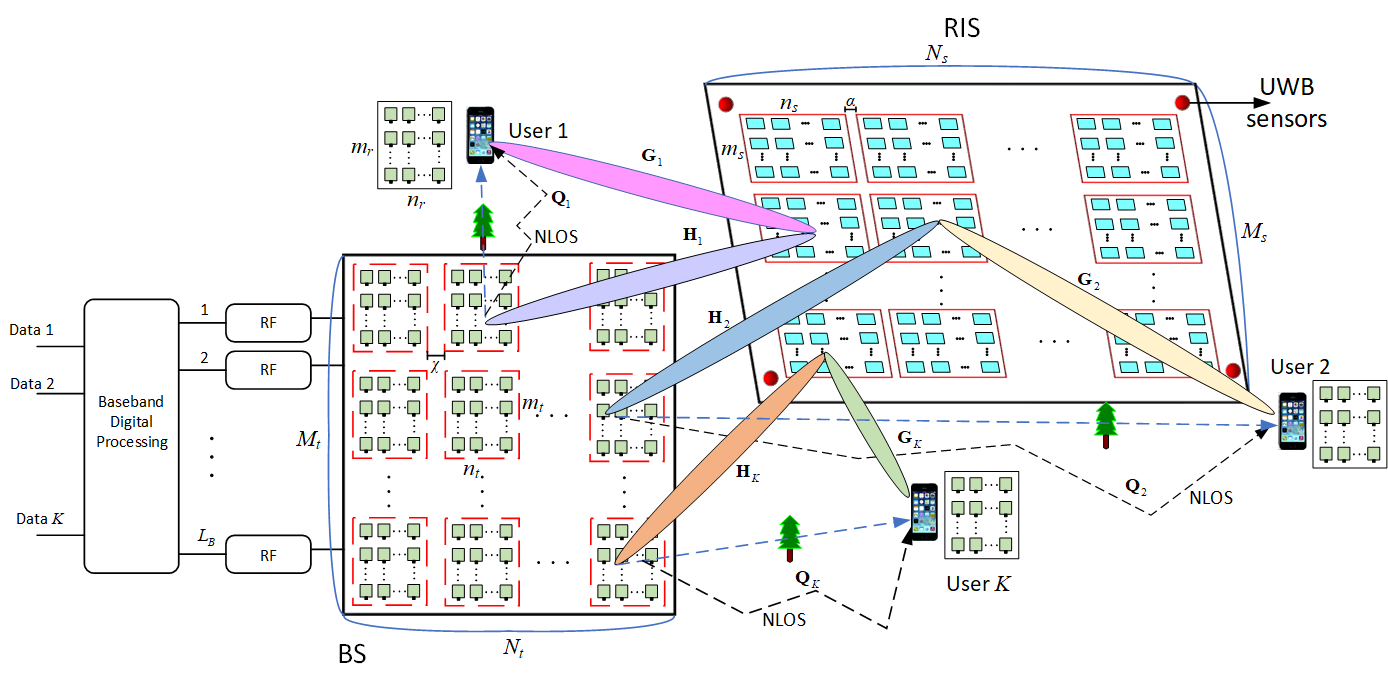
In THz communications, the link from the BS to the user may be blocked. Hence we assume that the line-of-sight (LOS) link from the BS to each user is indeed blocked, and a RIS is applied for improving the link spanning from the BS to the user by reflecting the signal. The RIS consists of a sub-wavelength UPA having passive reflecting elements under the control of an RIS controller. The THz channel is highly frequency-selective, but there are several low-attenuation windows separated by high-attenuation spectral nulls owing to molecular absorption [30]. Therefore, we can adaptively partition the total bandwidth into numerous subbands. If the bandwidth of the subband adopted is small enough, the channel can be regarded as non-frequency-selective and the noise power spectral density appears to be locally flat. In the following, we will discuss the direct path spanning from the BS to the user and that from the BS to the user via RIS, i.e., the BS-RIS-UE path.
(1) The direct BS-user path
The received signal of user can be expressed as
| (1) |
where is a vector containing the transmitted symbols of users, so that , where denotes the total initial transmit power and the same power is assigned to each user. In (1), is the THz channel matrix between the BS and user . The LOS components of the direct BS-user links are blocked by obstacles, so we assume that the direct link channel contains only non-line-of-sight (NLOS) components; is the analog transmit beamforming matrix representing the equal power splitters and phase shifters. For the array-of-subarray structure of (1), is block-diagonal structure and can be expressed as
| (2) |
where is an vector with , , and . Still referring to (1), is the baseband digital beamforming matrix used for interference mitigation, where we have
| (3) |
with
| (4) |
is a vector of the kth user; is the receive analog beamforming vector applied by user with , , and ; is the Gaussian noise vector at user , i.e., , .
(2) The RIS-aided path
The RIS consists of a sub-wavelength UPA having passive reflecting elements. According to the subarray structure of the BS, we also partition the RIS into sub-RISs. The th sub-RIS consists of elements, . Each sub-RIS is the dual counterpart of every subarray of the BS. Thus, we have . The adjacent elements are separated by , where is the Surface Plasmon Polariton (SPP) wavelength [4], so the mutual coupling between the elements is neglected. For simplicity and without loss of generality, we let , .
Let the THz channels spanning from the BS to RIS, and from the RIS to user , be denoted by and , respectively. The RIS reflection matrix is denoted by and the reflection matrix from the th sub-RIS to user is denoted by . For the sub-RIS structure, is an block matrix
| (5) |
where is an matrix; , where , is the phase of the -th reflection element in the k-th sub-RIS, . Without loss of generality, we assume that the k-th sub-RIS serves the k-th user. So the number of serving sub-RISs satisfies .
The received signal of user can be expressed as
| (6) |
where is the element channel matrix of the line spanning from the BS to the RIS. Furthermore, is the channel matrix of the line emerging from the RIS to the user k. Observe that can also be expressed in the form of the desired and interference terms as follows:
| (7) |
The RIS-aided THz channels are assumed to consist a direct BS-RIS ray from LOS propagation and some indirect BS-RIS rays from NLOS propagation due to reflection and scattering [28]. Thus, and are modeled by
| (8) |
| (9) |
where and represent the LOS components, while and denote the NLOS components; (), ( are the azimuth and elevation AODs (angle of departure) at the -th BS subarray, respectively; (), () are the azimuth and elevation AOAs (angle of arrival) at the -th user, respectively; (), are the azimuth and elevation AOAs from the -th BS subarray to the -th sub-RIS, respectively; (), () are the azimuth and elevation AODs from the -th sub-RIS to the -th user, respectively; and are the numbers of NLOS components; and denote the corresponding THz LOS complex gains given by
| (10) |
where and are the corresponding THz LOS path-loss, is the absorption coefficient at frequency , is the distance from the BS to the RIS, is the distance from the RIS to the user, both for user , and is the speed of light. Still referring to (8) and (9), and denote the corresponding THz NLOS complex gains.
In Eq. (8) and (9), , and are the antenna array steering vectors at the k-th BS subarray and -th user, respectively:
| (11) | ||||
where and denote the index of the BS antenna element, , . Additionally, is the distance between the BS antenna elements, and represents the wavelength of THz signals. Still referring to (9), we have
| (12) | ||||
where and denote the index of the user antenna element, , ; and is the distance between the user antenna elements.
Explicitly, and in Eq. (8) and (9) are the arrival and departure steering vectors at the -th sub-RIS, respectively. They can be expressed as follows:
| (13) | ||||
| (14) | ||||
where and denote the index of the RIS element, , ; and is the distance between the RIS elements within the -th sub-RIS.
Therefore, upon combining (1) and (6), the signal received by user from the BS-user and from the BS-RIS-user channels can be expressed as
| (15) |
The THz channels are sparse and only few paths exists [28]. Moreover, the power difference of the THz signals between the LOS and NLOS path is significant. Specifically, the power of the first-order reflected path is attenuated by more than 10 dB on average compared to the LOS path and that of the second-order reflection by more than 20 dB [28], so THz channels are LOS-dominant and the small-scale fading can be ignored. Thus, we will focus on the LOS path of the THz signal when exploring the channel condition, while relying on a RIS, and on beamforming schemes. Furthermore, considering the beamforming gain of the transceivers and the gains of the RIS, the received power of the BS-user link in (15) is much lower than that of the BS-RIS-user link.
III Conditions of Spatial Multiplexing for RIS-aided THz Channels
In this section, we discuss the conditions of achieving high multiplexing gains for RISs-aided THz channels. As the propagation of signals at THz frequencies is “quasi-optical”, the LOS path dominates the channel complemented only by a few non-LOS (NLOS) reflected rays due to the associated high reflection loss. Thanks to the beamforming gain and flexible placement of RISs, a LOS path may be present between each pair of the BS subarrays, the sub-RIS and the user’s receiver subarrays. To achieve high multiplexing gains in strong LoS environments at high frequencies [4], the antenna spacing of both the TX and RX together with that of the RIS element spacing should be set much larger than the operating THz wavelength.
We first consider the BS-RIS channel. We denote the distances between two adjacent subarrays at the BS transmitter and two adjacent sub-RIS respectively by and . Without loss of generality, we assume symmetry in the remainder of the paper, i.e., , . Thus, the BS contains subarrays and the RIS contains sub-RISs. The capacity is maximized when all columns of are orthogonal. Hence we formulate Theorem 1 as follows.
Theorem 1.
To achieve spatial multiplexing gain for the BS to the RIS line, the optimal spacing of sub-RISs is
| (16) |
for integer values of , where is the distance from the BS to the RIS, while is the wavelength of the THz signal.
Proof:
The proof is given in Appendix A. ∎
Theorem 2.
To achieve a high spatial multiplexing gain for the RIS to BS uplink, the optimal spacing of the BS subarrays is
| (17) |
for integer values of , where is the distance from the RIS to the BS, and is the wavelength of the THz signal.
Proof:
The proof is similar to that of Theorem 1, hence it is omitted here. ∎
Therefore, condition (16) and condition (17) guarantee having an optimal sub-RIS and BS subarray design, respectively.
The separation of elements in the BS subarrays or sub-RISs may be achieved via spatial interleaving. Moreover, the required spacing can be realized by choosing the right elements belonging to each BS subarray or sub-RIS. Each BS subarray associated with the corresponding sub-RIS may focus on a specific individual subband of the THz signal and can also be tuned flexibly according to the different user distances.
Let us now consider the channels spanning from the sub-RISs to the users. At the receiver side, each user has a subarray and is generally separated, so the distance of two adjacent user subarrays is usually large. Naturally, we cannot impose any constraints on the user positions, which tend to be random. So we must resort to exploiting the frequency selectivity of the THz channels for spatial multiplexing. According to [28], the THz channels have limited angular spread of about . Since the beam steering vectors associated with completely different angles of large-scale antennas are nearly orthogonal, for the channels spanning from the ith and the kth sub-RIS to user k, we have
| (18) |
As the RIS may be regarded as a large-scale antenna array, the channel from the RIS to the user can be nearly orthogonal, hence beneficial spatial multiplexing gains can be achieved. For users that are close enough to be within the angular spread, the pre-scanning and grouping technique of [28] can be adopted.
IV Path-loss of the RIS-aided Near-Field and Far-Field THz Channel
Based on the assumption that the spherical wave generated by the transmitter can be approximately regarded as a plane wave at the RIS side when a transmitter is far away from the RIS, the far-field and near-field boundary of the antenna array is defined as , where , and represent the distance between the transmitter and the center of the antenna array, the maximum dimension of the antenna array and the wavelength of the signal, respectively [29]. For the sub-RIS case, we have
| (19) |
Generally, , so we get
| (20) |
Let us now discuss the THz channel path-loss in the near-field and far-field of a RIS, respectively. Let us represent the RIS-aided cascaded channel by
| (21) |
Theorem 3.
For near-field beamforming over the RIS-aided THz channel, the path-loss of can be expressed by
| (22) |
Proof:
Theorem 4.
For far-field beamforming over the RIS-aided THz channel, the path-loss of can be expressed as
| (23) |
V Sensor-based Channel Estimation Scheme
In this section, we propose a location-aided channel estimation scheme. The location information obtained by the sensor allows us to expedite the channel estimation and beamforming processes. This is the first location-aware channel estimator for THz channels.
Given the RIS-aided THz channel models of Section II, estimating the RIS-aided channel is equivalent to inferring the parameters of the channel paths; namely the AoA, the AoD, and the path-loss of each path. The RIS locations are generally known by the BS. Four UWB sensors are integrated into the four corners of the RIS, as shown in Fig. 1, which is the minimum number of UWB nodes required for supporting 3D localization. Thanks to the ultra-low power density and 3.1-10.6 GHz frequency band of UWB, the interference between the UWB ranging signal and the THz signals is negligible. The distance between each UWB sensor and the user can be estimated using either a Time-of-Arrival (TOA) or Two-Way Time of-Flight (TW-ToF) based ranging method [31]. However, they introduce the ranging error . Then, the 3D user position can be determined by multi-lateration algorithm upon solving a set of nonlinear equations:
| (24) |
where , indicates the coordinates of each UWB node on the RIS, is the unknown user position, and is the measurement of the distance between the UWB sensors and the UE. Given the ranging error , an approximate of (24) must be used instead of the intersection of four spheres at a single point found in the ideal scenario [31].
We then adopt the user location information provided by the UWB sensors to obtain angle and path-loss of the LOS path. The LOS path-loss can be readily calculated from the BS-user and from the RIS-user distance according to (22) and (23). The AOD/AOA of the LOS path can be inferred by trigonometry as follows.
Without loss of generality, the -th BS subarray and the -th sub-RIS of Fig. 1 are assumed to be located at and , respectively. Then the effective AOA at the -th sub-RIS from the -th BS subarray can be calculated as
| (25) |
| (26) |
where .
Similarly, the effective AOD from the -th BS subarray to the -th sub-RIS are:
| (27) |
| (28) |
Let denote the estimated location of user k obtained by the UWB sensors.The k-th sub-RIS calculates its effective AOD from itself to the k-th user as
| (29) |
| (30) |
where .
Similarly, the k-th user calculates its effective AOA from itself to the k-th sub-RIS as
| (31) |
| (32) |
Furthermore, by substituting and into (10), we can obtain the channel gain and .
V-A Analog Active Beamforming Relying on User Locations
Then, the estimated angle information can be used to design the BS subarray’s active beamforming and sub-RIS’s passive beamforming. However, because the active and the passive beamforming are coupled, the optimization problem is nonconvex, so the global optimum is typically a challenge to find. Although some suboptimal algorithms have been proposed for MISO systems relying on alternating optimization [14], the computational complexity of these algorithms is excessive because of the large number of reflection elements. Hence we circumvent this challenge by opting for the low-complexity separate optimization of the BS subarray and of each sub-RIS, because then convenient closed-form solutions can be obtained. Specifically, the BS utilizes the angle information of the BS-RIS link to design the active beamforming. Without loss of generality, we assume that the k-th user is assisted by the k-th sub-RIS. Thus, the active beamforming designed for the -th user should be aligned to the -th sub-RIS. As such, the transmit beam of the -th BS subarray is designed as
| (33) |
where is the transmit power of the k-th BS subarray. Therefore, the channel between the BS and RIS can be readily estimated with the aid of the previously calibrated accurate angles, and we would only focus our attention on the estimation of the time-variant RIS-UE channels.
The received beam of the -th user is given by
| (34) |
V-B RIS Phase Shift Based Passive Beamforming Relying on User Locations
We then use the estimated angle information of the RIS-user link for the RIS phase shift based passive beamforming design. The -th user’s received signal is maximized with the k-th sub-RIS by optimizing the phase shift beam . The optimization problem can be formulated as:
| (35) |
According to with , we have
| (36) | ||||
Thus, the objective function in (35) becomes
| (37) |
According to (4) and (33), is a constant independent of , so the optimization problem equals to
| (38) |
Hence, the solution of the above optimization problem is
| (39) |
Using the estimated angles calculated from the position information obtained by the UWB sensors, we design the RIS phase shift beam as
| (40) |
where
Based on (34) and (40), both the phase shift based beamforming and the UE’s receiver beamforming both depend on the angles calculated from the estimated user location information obtained by the UWB sensors, which contains positioning errors. The inevitable positioning errors will result in passive transmit beamforming misalignment with the user, which is further aggravated by the UE’s receiver beamforming misalgnment with the RIS’ transmit beam. Given the extremely narrow pencil beam characteristics of THz signals, the system’s performance will thus be severely degraded.
Without being constrained by the positioning errors of the UWB sensors, we further propose the Precise Beamforming Algorithm (PBA) for the joint RIS phase shift based beamforming and for the UE’s receiver beamforming design.
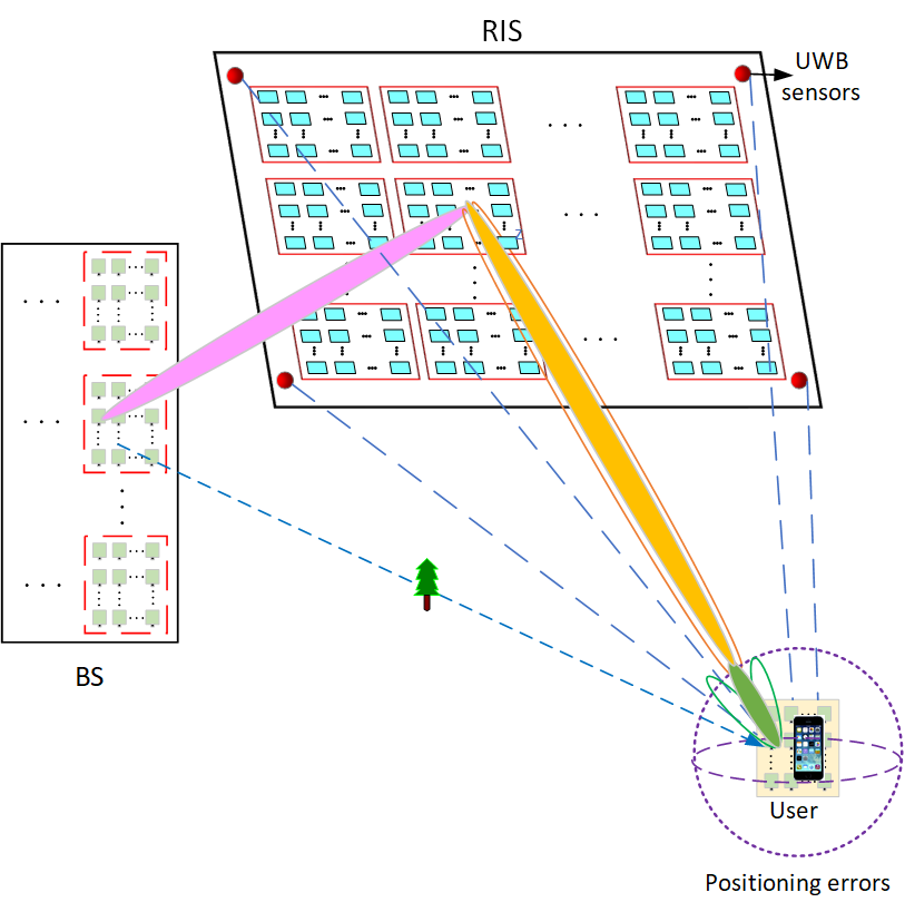
V-C Precise Beamforming Algorithm for joint RIS Phase Shift and UE Receiver Beamforming
As shown in Fig. 2, we propose the PBA for the improved alignment of the RIS’s phase shift based beamforming and the UE’s receiver beamforming. The accurate position of the th UE denoted by can be assumed to be uniformly distributed within a sphere with the radius (for UWB positioning, generally m) and center
The algorithm is formulated as follows:
1: Input: The receiver beamforming (RBF) codebook at the UE and the phase shift based beamforming codebook at the RIS (RIS-BF).
2: Locate all the users by the UWB sensors.
3: For do
4: According to (40), obtain the initial RIS-BF for the th sub-RIS.
5: According to (34), obtain the initial RBF for user .
6: Select the sub-codebook from to obtain within the range of the UWB positioning errors.
7: Select the sub-codebook from to obtain within the range of the UWB positioning errors.
Repeat
8: Search to find the optimal RBF for the th UE so that .
9: Search to find the optimal RIS-BF for the th sub-RIS so that .
until is maximized.
10: end for
11: Output: and , .
It is worth mentioning that the results of may also be fed back to the UWB positioning system for improving its accuracy, which is also a further benefit of joint sensing and communication.
V-D Complexity Analysis
In this subsection, we compare the search complexity of our proposed schemes to those of other beam training schemes [19]. The results are shown in Table II. Compared to other schemes, the search time of our proposed scheme is negligible and unrelated to , thanks to the high-precision UWB positioning. By contrast, the complexity of the benchmarks increases. Therefore, the proposed scheme is eminently suitable for time-varying user positions or delay-sensitive applications.
| Beam training schemes | Applicable to RIS-aided system | Applicable to THz | Search time for RIS-aided system |
|---|---|---|---|
| Exhaustive search | Yes | Yes | |
| One-side search [32] | No | No | |
| Adaptive binary-tree search [33] | No | No | |
| Two-stage training scheme [34] | No | Yes | |
| Tree dictionary (TD) and PS deactivation (PSD) codebook based search [19] | Yes | Yes | (TD) or (PSD) |
| Proposed sensor-based scheme with PBA | Yes | Yes | Negligible and not related to |
V-E Design of the BS’s Digital Precoder
Following the beam training and channel estimation using sensor based PBA, we will now design the digital transmit precoder (TPC) for interference cancellation among different users. Given the effective channel estimated above, the digital TPC can be designed as follows. Let
| (41) |
Specifically, the minimum mean squared error (MMSE) TPC is formulated as
| (42) |
The Zero-forcing (ZF) digital TPC employed as a benchmark is formulated as:
| (43) |
where , and is a diagonal matrix representing the digital TPC power so that Particularly, the k-th diagonal element of is given by .
VI Performance Analysis
Based on the received signal (15), in this section, we characterize the system performance in terms of the achievable sum-rate of the users expressed by
| (44) |
where we have:
| (45) |
According to the orthogonality of different users arranged by the sub-RIS and subarray of the BS, which is achieved by the conditions shown in Section III, as well as the previous digital TPC, we have
| (46) |
Therefore, we arrive at:
| (47) |
VII Simulation Results and Discussions
In this section, we evaluate the performance of our sensor-based channel estimation scheme proposed for RIS-aided THz MIMO systems. We consider both the near-field and far-field of RIS-BF. There are 4 users having different positions. At the BS, each RF chain is connected to a single sub-arrray and each subarray corresponds to a user. As there is a low-attenuation THz transmission window at 350 GHz [30], we consider the THz frequency band at 350 GHz in the simulations. The number of channels between the user and the BS is set to 3 due to the sparsity of the THz channels [28]. The simulation parameters are shown in Table III. The user locations are generated randomly and the channel conditions of (18) are satisfied. For the system operating without RIS, the channel state information (CSI) is assumed to be perfectly estimated by the BS. For the RIS-aided system, the BS initially does not know the CSI and the channel estimation is conducted based on our proposed scheme. The simulations are conducted in Matlab and 100,000 random runs are performed.
| Parameters | Symbols | Values |
|---|---|---|
| Center frequency of the subband | GHz | |
| Noise power | −75 dBm | |
| Bandwidth | 1 GHz | |
| Number of Users | 4 | |
| Location of the center of the RIS | (0, 0, 0) | |
| Location of the center of the BS in the nearfield case | (-0.6, -0.7, 0.4) | |
| Locations of the users in the nearfield case | (0, 0, 1.1), (0, 0.45, 0.22), (0.742, 0, 0.3), (0.71, 0.7, 0.1) | |
| Location of the center of the BS in the farfield case | (-4, -4, -2) | |
| Locations of the users in the farfield case | (2, 2, 1), (0, 3.4, 0.85), (4, 0, 2.07), (0, 0, 5.8) |
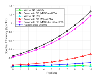
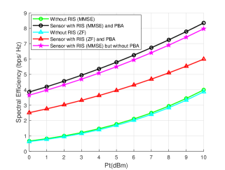
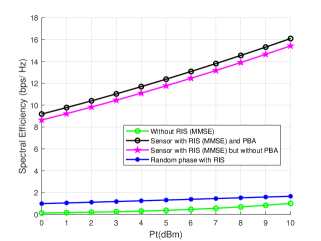
For the far-field scenario, we first assume that each BS antenna subarray is a UPA and each user is equipped with one RF chain associated with a UPA subarray. Each sub-RIS is also a UPA. According to (20), we have m. Then we increase the BS antenna subarray, RIS subarray and user subarray to UPA and UPA. The boundary is m and m, correspondingly. Therefore, as both the BS and users are in the far-field of the RIS, the locations of the center of the BS arrays and of the RIS are generated randomly, and shown in Table III. For the RIS-aided channel, the distance between the BS and the RIS is 6 m while the distances between the RIS and the users are 3 m, 4.5 m, 3.5 m and 5.8 m, respectively. The simulation results are shown in Fig. 3 (a)-(c). Observe that without the proposed sensor based channel estimation the performance of RIS-aided channel associated with random phase is only a little better than that without the RIS. For comparison, our proposed scheme achieves much higher spectral efficiency than the original system operating without the RIS. Moreover, the sensor based PBA scheme achieves higher spectral efficiency than that without it, because the PBA further eliminates the effect of sensor positioning errors. Additionally, the proposed MMSE scheme outperforms its ZF counterpart since ZF may cause noise amplification. Thus, we only characterize the proposed MMSE-based scheme in the following simulations.
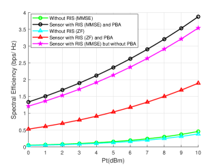
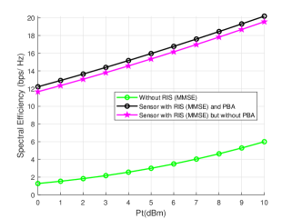
For the near-field scenario, each sub-RIS is a UPA. According to (20), the boundary is m. Then we increase the dimensions of the BS subarray and user subarray from UPA to UPA. Since both the BS and users are in the near-field of RIS, the locations of the center of the BS and the RIS are generated randomly and are also shown in Table III. The distance between the BS and the RIS is 1 m, while the distances between the RIS and the users are 1 m, 0.5 m, 1.1 m and 0.8 m, respectively. The simulation results are shown in Fig. 4 (a) and (b). Observe that our proposed scheme can also achieve much higher spectral efficiency than the original system operating without RIS. Furthermore, the spectral efficiency of the sensor-based PBA scheme is higher than that of the scheme without PBA. Furthermore, the spectral efficiency in the near-field scenario is much higher than in the far-field scenario, as the path-loss is more severe in the far-field case, which indicates that for better system performance, we can use more RIS elements to create near-field communication for the THz signals.
VIII Conclusions
A novel hybrid 3D beamforming and sensor-based channel estimation scheme is proposed in this paper for RIS-aided THz MIMO systems. The user location obtained by UWB sensors is employed for RIS-BF and user RBF. A PBA is also proposed for improving the beam alignment accuracy. Compared to the benchmarks, our proposed scheme has lower complexity and search time. We have also derived the conditions of channel orthogonality for the RIS-aided THz channel to achieve high-integrity spatial multiplexing. Moreover, the closed-form expressions of the near-field and far-field path-loss of the RIS-aided THz channel are derived. Our simulation results show that the proposed scheme accurately estimates the RIS-aided THz channel and the spectral efficiency with RIS is much higher than that without RIS. Both the near-field and far-field scenarios demonstrate the benefits of our proposed scheme. As our future work, other forms of ISAC will be explored for RIS-aided THz MIMO systems.
IX Appendix A
Proof of Theorem 1
Proof:
Let and be the coordinates of two arbitrary BS transmit subarrays and be arbitrary coordinates of a sub-RIS. The effective distance from the centers of the BS subarray and the sub-RIS is
| (48) |
For , according to the binomial approximation, we have
| (49) |
So we can readily derive the inner product between the corresponding channel columns as
| (50) | ||||
The channels are orthogonal when . Therefore, without imposing any restrictions on the steering vectors, we can obtain the following optimal value,
| (51) |
for integer values of . ∎
References
- [1] H. Elayan, O. Amin, B. Shihada, R. M. Shubair, and M.-S. Alouini, “Terahertz Band: The Last Piece of RF Spectrum Puzzle for Communication Systems,” IEEE Open J. Commun. Soc., vol. 1, pp. 1–32, 2020. [Online]. Available: https://ieeexplore.ieee.org/document/8901159/
- [2] X. Wang, P. Wang, M. Ding, Z. Lin, F. Lin, B. Vucetic, and L. Hanzo, “Performance Analysis of Terahertz Unmanned Aerial Vehicular Networks,” IEEE Trans. Veh. Technol., vol. 69, no. 12, pp. 16 330–16 335, Dec. 2020. [Online]. Available: https://ieeexplore.ieee.org/document/9248588/
- [3] I. F. Akyildiz and J. M. Jornet, “Realizing Ultra-Massive MIMO (1024*1024) communication in the (0.06-10) Terahertz band,” Nano Communication Networks, vol. 8, pp. 46–54, Jun. 2016. [Online]. Available: https://linkinghub.elsevier.com/retrieve/pii/S1878778916000107
- [4] H. Sarieddeen, M.-S. Alouini, and T. Y. Al-Naffouri, “Terahertz-Band Ultra-Massive Spatial Modulation MIMO,” IEEE J. Select. Areas Commun., vol. 37, no. 9, pp. 2040–2052, Sep. 2019. [Online]. Available: https://ieeexplore.ieee.org/document/8765243/
- [5] C. Lin and G. Y. Li, “Energy-Efficient Design of Indoor mmWave and Sub-THz Systems with Antenna Arrays,” IEEE Trans. Wireless Commun., pp. 1–1, 2016. [Online]. Available: http://ieeexplore.ieee.org/document/7436794/
- [6] X. Ma, Z. Chen, W. Chen, Z. Li, Y. Chi, C. Han, and S. Li, “Joint Channel Estimation and Data Rate Maximization for Intelligent Reflecting Surface Assisted Terahertz MIMO Communication Systems,” IEEE Access, vol. 8, pp. 99 565–99 581, 2020. [Online]. Available: https://ieeexplore.ieee.org/document/9091552/
- [7] C. Pan, H. Ren, K. Wang, M. Elkashlan, A. Nallanathan, J. Wang, and L. Hanzo, “Intelligent Reflecting Surface Aided MIMO Broadcasting for Simultaneous Wireless Information and Power Transfer,” IEEE J. Select. Areas Commun., vol. 38, no. 8, pp. 1719–1734, Aug. 2020. [Online]. Available: https://ieeexplore.ieee.org/document/9110849/
- [8] C. Pan, H. Ren, K. Wang, J. F. Kolb, M. Elkashlan, M. Chen, M. Di Renzo, Y. Hao, J. Wang, A. L. Swindlehurst, X. You, and L. Hanzo, “Reconfigurable Intelligent Surfaces for 6G Systems: Principles, Applications, and Research Directions,” IEEE Commun. Mag., vol. 59, no. 6, pp. 14–20, Jun. 2021. [Online]. Available: https://ieeexplore.ieee.org/document/9475160/
- [9] Q. Wu and R. Zhang, “Intelligent Reflecting Surface Enhanced Wireless Network via Joint Active and Passive Beamforming,” IEEE Trans. Wireless Commun., vol. 18, no. 11, pp. 5394–5409, Nov. 2019. [Online]. Available: https://ieeexplore.ieee.org/document/8811733/
- [10] M. Di Renzo, A. Zappone, M. Debbah, M.-S. Alouini, C. Yuen, J. de Rosny, and S. Tretyakov, “Smart Radio Environments Empowered by Reconfigurable Intelligent Surfaces: How It Works, State of Research, and The Road Ahead,” IEEE J. Select. Areas Commun., vol. 38, no. 11, pp. 2450–2525, Nov. 2020. [Online]. Available: https://ieeexplore.ieee.org/document/9140329/
- [11] S. Zhang and R. Zhang, “Capacity Characterization for Intelligent Reflecting Surface Aided MIMO Communication,” IEEE J. Select. Areas Commun., vol. 38, no. 8, pp. 1823–1838, Aug. 2020. [Online]. Available: https://ieeexplore.ieee.org/document/9110912/
- [12] J. Ye, S. Guo, and M.-S. Alouini, “Joint Reflecting and Precoding Designs for SER Minimization in Reconfigurable Intelligent Surfaces Assisted MIMO Systems,” IEEE Trans. Wireless Commun., vol. 19, no. 8, pp. 5561–5574, Aug. 2020. [Online]. Available: https://ieeexplore.ieee.org/document/9097454/
- [13] C. Huang, A. Zappone, G. C. Alexandropoulos, M. Debbah, and C. Yuen, “Reconfigurable Intelligent Surfaces for Energy Efficiency in Wireless Communication,” IEEE Trans. Wireless Commun., vol. 18, no. 8, pp. 4157–4170, Aug. 2019. [Online]. Available: https://ieeexplore.ieee.org/document/8741198/
- [14] H. Guo, Y.-C. Liang, J. Chen, and E. G. Larsson, “Weighted Sum-Rate Maximization for Reconfigurable Intelligent Surface Aided Wireless Networks,” IEEE Trans. Wireless Commun., vol. 19, no. 5, pp. 3064–3076, May 2020. [Online]. Available: https://ieeexplore.ieee.org/document/8982186/
- [15] X. Wei, D. Shen, and L. Dai, “Channel Estimation for RIS Assisted Wireless Communications-Part I: Fundamentals, Solutions, and Future Opportunities,” IEEE Commun. Lett., vol. 25, no. 5, pp. 1398–1402, May 2021. [Online]. Available: https://ieeexplore.ieee.org/document/9328501/
- [16] A. M. Elbir, A. Papazafeiropoulos, P. Kourtessis, and S. Chatzinotas, “Deep Channel Learning for Large Intelligent Surfaces Aided mm-Wave Massive MIMO Systems,” IEEE Wireless Commun. Lett., vol. 9, no. 9, pp. 1447–1451, Sep. 2020. [Online]. Available: https://ieeexplore.ieee.org/document/9090876/
- [17] Z.-Q. He and X. Yuan, “Cascaded Channel Estimation for Large Intelligent Metasurface Assisted Massive MIMO,” IEEE Wireless Commun. Lett., vol. 9, no. 2, pp. 210–214, Feb. 2020. [Online]. Available: https://ieeexplore.ieee.org/document/8879620/
- [18] S. Liu, Z. Gao, J. Zhang, M. D. Renzo, and M.-S. Alouini, “Deep Denoising Neural Network Assisted Compressive Channel Estimation for mmWave Intelligent Reflecting Surfaces,” IEEE Trans. Veh. Technol., vol. 69, no. 8, pp. 9223–9228, Aug. 2020. [Online]. Available: https://ieeexplore.ieee.org/document/9127834/
- [19] B. Ning, Z. Chen, W. Chen, Y. Du, and J. Fang, “Terahertz Multi-User Massive MIMO With Intelligent Reflecting Surface: Beam Training and Hybrid Beamforming,” IEEE Trans. Veh. Technol., vol. 70, no. 2, pp. 1376–1393, Feb. 2021. [Online]. Available: https://ieeexplore.ieee.org/document/9325920/
- [20] X. Hu, C. Zhong, Y. Zhang, X. Chen, and Z. Zhang, “Location Information Aided Multiple Intelligent Reflecting Surface Systems,” IEEE Trans. Commun., vol. 68, no. 12, pp. 7948–7962, Dec. 2020. [Online]. Available: https://ieeexplore.ieee.org/document/9181610/
- [21] S. Sharma, A. Gupta, and V. Bhatia, “IR-UWB Sensor Network Using Massive MIMO Decision Fusion: Design and Performance Analysis,” IEEE Sensors J., vol. 18, no. 15, pp. 6290–6302, Aug. 2018. [Online]. Available: https://ieeexplore.ieee.org/document/8374926/
- [22] F. Liu, C. Masouros, A. P. Petropulu, H. Griffiths, and L. Hanzo, “Joint Radar and Communication Design: Applications, State-of-the-Art, and the Road Ahead,” IEEE Trans. Commun., vol. 68, no. 6, pp. 3834–3862, Jun. 2020. [Online]. Available: https://ieeexplore.ieee.org/document/8999605/
- [23] T. Wild, V. Braun, and H. Viswanathan, “Joint Design of Communication and Sensing for Beyond 5G and 6G Systems,” IEEE Access, vol. 9, pp. 30 845–30 857, 2021. [Online]. Available: https://ieeexplore.ieee.org/document/9354629/
- [24] J. Moghaddasi and K. Wu, “Multifunctional Transceiver for Future Radar Sensing and Radio Communicating Data-Fusion Platform,” IEEE Access, vol. 4, pp. 818–838, 2016. [Online]. Available: http://ieeexplore.ieee.org/document/7409935/
- [25] J. A. Zhang, X. Huang, Y. J. Guo, J. Yuan, and R. W. Heath, “Multibeam for Joint Communication and Radar Sensing Using Steerable Analog Antenna Arrays,” IEEE Trans. Veh. Technol., vol. 68, no. 1, pp. 671–685, Jan. 2019. [Online]. Available: https://ieeexplore.ieee.org/document/8550811/
- [26] F. Liu, C. Masouros, A. Li, H. Sun, and L. Hanzo, “MU-MIMO Communications With MIMO Radar: From Co-Existence to Joint Transmission,” IEEE Trans. Wireless Commun., vol. 17, no. 4, pp. 2755–2770, Apr. 2018. [Online]. Available: https://ieeexplore.ieee.org/document/8288677/
- [27] X. Chen, Z. Feng, Z. Wei, F. Gao, and X. Yuan, “Performance of Joint Sensing-Communication Cooperative Sensing UAV Network,” IEEE Trans. Veh. Technol., vol. 69, no. 12, pp. 15 545–15 556, Dec. 2020. [Online]. Available: https://ieeexplore.ieee.org/document/9282206/
- [28] C. Lin and G. Y. Li, “Adaptive Beamforming With Resource Allocation for Distance-Aware Multi-User Indoor Terahertz Communications,” IEEE Trans. Commun., vol. 63, no. 8, pp. 2985–2995, Aug. 2015. [Online]. Available: http://ieeexplore.ieee.org/document/7116524/
- [29] W. Tang, M. Z. Chen, X. Chen, J. Y. Dai, Y. Han, M. Di Renzo, Y. Zeng, S. Jin, Q. Cheng, and T. J. Cui, “Wireless Communications With Reconfigurable Intelligent Surface: Path Loss Modeling and Experimental Measurement,” IEEE Trans. Wireless Commun., vol. 20, no. 1, pp. 421–439, Jan. 2021. [Online]. Available: https://ieeexplore.ieee.org/document/9206044/
- [30] A. Moldovan, M. A. Ruder, I. F. Akyildiz, and W. H. Gerstacker, “LOS and NLOS channel modeling for terahertz wireless communication with scattered rays,” in 2014 IEEE Globecom Workshops (GC Wkshps). Austin, TX, USA: IEEE, Dec. 2014, pp. 388–392. [Online]. Available: http://ieeexplore.ieee.org/document/7063462/
- [31] F. Lazzari, A. Buffi, P. Nepa, and S. Lazzari, “Numerical Investigation of an UWB Localization Technique for Unmanned Aerial Vehicles in Outdoor Scenarios,” IEEE Sensors J., vol. 17, no. 9, pp. 2896–2903, May 2017. [Online]. Available: http://ieeexplore.ieee.org/document/7882672/
- [32] T. Nitsche, C. Cordeiro, A. Flores, E. Knightly, E. Perahia, and J. Widmer, “IEEE 802.11ad: directional 60 GHz communication for multi-Gigabit-per-second Wi-Fi [Invited Paper],” IEEE Commun. Mag., vol. 52, no. 12, pp. 132–141, Dec. 2014. [Online]. Available: http://ieeexplore.ieee.org/document/6979964/
- [33] A. Alkhateeb, O. El Ayach, G. Leus, and R. W. Heath, “Channel Estimation and Hybrid Precoding for Millimeter Wave Cellular Systems,” IEEE J. Sel. Top. Signal Process., vol. 8, no. 5, pp. 831–846, Oct. 2014. [Online]. Available: https://ieeexplore.ieee.org/document/6847111/
- [34] C. Lin, G. Y. Li, and L. Wang, “Subarray-Based Coordinated Beamforming Training for mmWave and Sub-THz Communications,” IEEE J. Select. Areas Commun., vol. 35, no. 9, pp. 2115–2126, Sep. 2017. [Online]. Available: http://ieeexplore.ieee.org/document/7959180/