Secure Rate-Splitting for MIMO Broadcast Channel with Imperfect CSIT and a Jammer
Abstract
In this paper, we investigate the secure rate-splitting for the two-user multiple-input multiple-output (MIMO) broadcast channel with imperfect channel state information at the transmitter (CSIT) and a multiple-antenna jammer, where each receiver has an equal number of antennas and the jammer has perfect channel state information (CSI). Specifically, we design a secure rate-splitting multiple-access strategy, where the security of split private and common messages is ensured by precoder design with joint nulling and aligning the leakage information, regarding different antenna configurations. Moreover, we show that the sum-secure degrees-of-freedom (SDoF) achieved by secure rate-splitting is optimal and outperforms that by conventional zero-forcing. Therefore, we reveal the sum-SDoF of the two-user MIMO broadcast channel with imperfect CSIT and a jammer, and validate the superiority of rate-splitting for the security purpose in this scenario with emphasis of MIMO.
Index Terms:
Broadcast channel, MIMO, rate-splitting, imperfect CSIT, secure degrees of freedomI Introduction
For the 6G cellular networks, the rate-splitting (RS) is a prospective solution for multi-user (massive) multiple-access technology, due to its nature of non-orthogonal transmission and robust interference management [1, 2, 3]. It was shown in [4, 5] that RS can achieve the maximal multiplexing gain in multiple-input multiple-output (MIMO) networks with imperfect channel state information at the transmitter (CSIT), where the maximal multiplexing gain indicates the maximal number of interference-free data streams and is recognized as the name “degrees-of-freedom” in open literature. Likewise, the secure degrees-of-freedom (SDoF) stands for how many interference-free data streams with security guarantee can MIMO networks afford [6, 7, 8, 9, 10]. The secure RS (S-RS) is able to attain optimal SDoF, where a couple of initial results were disclosed in [11]. Although the design of [12] is SDoF-optimal, [12] is only limited to the -user multiple-input single-output (MISO) broadcast channel with imperfect CSIT and a jammer. Motivated by the SDoF optimality in the -user MISO broadcast channel, we investigate the S-RS in the two-user MIMO broadcast channel.
Recently, RS has attracted a plenty of research interests. It was shown in [13] that power partitioned rate-splitting multiple-access (RSMA) achieves the optimal DoF in an overloaded MISO broadcast channel with heterogeneous CSIT qualities. It was proven in [14] that a RS-based design achieves higher max-min DoF compared with conventional No RS designs. In [15], the optimal DoF Region of the -User MISO broadcast channel with imperfect CSIT was achieved by RS. For -cell MISO interference channel with an arbitrary CSIT quality of each interfering link, [16] identified the DoF region achieved by RS. Moreover, the applications of RS were discussed in integrated sensing and communication (ISAC) systems [17], intelligent reflecting surface (IRS) networks [18], satellite systems [19], and so on.
Due to the broadcast nature of wireless medium, the transmission signal may be wiretapped by eavesdroppers, thus arousing the security issue of wireless communications [20, 21, 22]. The solutions to security issue in RS has been studied in [23, 24, 25, 26, 27, 11]. To ensure the security of RS, the authors in [23] first considered the dual use of common message transmission and jamming functionalities in the two-user MISO broadcast channel with an external eavesdropper. In [24], the RS was designed in secure unmanned areal vehicle (UAV) networks. In [25], the secure sum-rate is maximized in the two-user MISO broadcast channel with an external eavesdropper. The adaptive beamforming strategy and power allocation was investigated in [26] two-user MISO broadcast channel with an external eavesdropper. The authors in [27] applied RS in polar codes for communication over a multiple-access wiretap channel with two transmitters under strong secrecy. In [11], for the -user MISO broadcast channel with imperfect CSIT and a multiple-antenna jammer, a S-RS design was proposed to achieve an exceptional sum-SDoF. However, all of the above works have not studied the MIMO broadcast channel scenario. Note that [28, 29] investigate RSMA in MIMO broadcast channel with multiple antennas at each receiver. But security is not considered. Therefore, the role of number of receive antennas on the secure rate splitting is still a research problem.
In this paper, motivated by the research pitfalls, we investigate the S-RS for the two-user MIMO broadcast channel with imperfect CSIT and a multiple-antenna jammer, where each receiver has equal number of antennas and the jammer has perfect CSIT. To the best of our knowledge, this is the first work that investigates the SDoF of secure rate-splitting in MIMO broadcast channel with multiple receive antennas. Specifically, we design transmit precoders to enable the S-RS by joint nulling and aligning the leakage information, regarding to different antenna configurations. Since the spatial benefits of MIMO settings are exploited, we show that the sum-SDoF achieved by S-RS is optimal and outperforms that by conventional zero-forcing, in the two-user broadcast channel with imperfect CSIT and a jammer.
Notations: Matrices and vectors are represented by upper and lowercase boldface letters, respectively. The operator and stand for Frobenius norm and expectation. refers to . represents the same order of .
II System Model
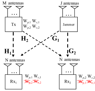
We consider a two-user MIMO broadcast channel with confidential messages (BCCM), where a -antenna transmitter aims to deliver two independent and confidential messages, to -antenna receivers 1 and 2, respectively, as depicted in Fig. 1. The message desired by receiver is denoted by . Besides, there is a jammer to assist the transmitter. The jammer is equipped with antennas, where . The channel between the transmitter and the receiver is denoted by . The channel between the jammer and the receiver is denoted by . The transmit signal111We will show the proposed S-RS design of transmit signals later on. of the transmitter is denoted by . The transmit signal of the jammer is denoted by . Thus, the received signal at the receiver can be written as
| (1) |
where the additive white Gaussian noise (AWGN) at receiver is denoted by , which follows complex Gaussian distribution with positive definite matrix . The total transmit power of the transmitter and jammer is bounded by a maximum power , which is written by . Due to imperfect channel estimation, it is reasonable to assume that the CSIT is imperfect. The jammer is assume to be more powerful than the transmitter, thus it has perfect CSI. According to [1, 2, 3], we have the following imperfect CSIT model:
| (2) |
where denotes the estimate CSI, and denotes the unknown complement of estimate CSI. Since the accuracy of channel estimation scale with signal-to-noise ratio (SNR), scales as , where . It can be seen that represents perfect CSIT case, while represents no CSIT case. We assume that the CSI at the receivers is perfect.
Denote the SNR as . A code with achievable rate and channel uses is defined below. A stochastic encoder at the transmitter, denoted by , encodes the confidential messages to an transmit signal based on . A jammer transmits artificial noise signal based on perfect CSI. A stochastic decoder at the receiver , denoted by , decodes the estimated desired confidential messages using CSI at receivers and received signals. Let us denote the estimated messages by . The reliability constraint is given by
| (3) |
where approaches as goes to infinity. Also, the code needs to satisfy the weak security constraint, given by
| (4a) | |||
| (4b) | |||
where the assemble of received signals of receiver across channel use is denoted by . The sum of secure capacity is defined as . The sum-SDoF, denoted by , is the first-order approximation of sum secure capacity in high SNR regime and defined as
| (5) |
III Main Results and Discussion
Theorem 1: For the two-user MIMO BCCM with imperfect CSIT and a jammer, defined in Section-II, the sum-SDoF lower bound achieved by the S-RS is given as follows:
| (6) |
Proof:
Please refer to Section-IV. ∎
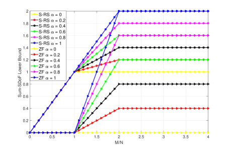
To examine the power of S-RS, we compare it with zero-forcing in Fig. 2, where zero-forcing achieves a sum-SDoF lower bound of given in [11]. Compared with trivial design (i.e., zero-forcing), our S-RS achieves substantial performance gain. In particular, except perfect CSIT case, our S-RS outperforms the zero-forcing in all antenna configurations. This is because we leverage the power of common message by RS. If CSIT is perfect, our S-RS beats zero-forcing when , and achieves the same performance as zero-forcing when . This shows our secure rate splitting is useful even the CSIT is perfect. Moreover, Fig. 2 shows that increasing will not always elevate the achieved sum-SDoF, as the achieved sum-SDoF in (6) saturates since .
Corollary 1: For the two-user MIMO BCCM with imperfect CSIT and a jammer, defined in Section-II, the sum-SDoF achieved by S-RS, i.e., (6), is SDoF-optimal.
Proof:
Please refer to Appendix A. ∎
Corollary 2: We consider the -user MIMO BCCM with imperfect CSIT and a jammer, where the number of antennas at the transmitter is not less than the sum of antennas at the receiver. The sum-SDoF lower bound achieved by the S-RS is given as follows:
| (7) |
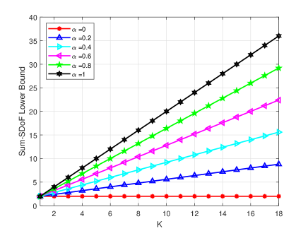
Proof:
In Fig. 3, we illustrate (7), i.e., Proposition 1, by setting . Fig. 3 shows the sum-SDoF lower bound increases with the number of receivers and CSIT quality . It can be found that the increment by enlarging CSIT quality becomes greater when the number of receivers increase.
IV The Proposed Secure Rate-Splitting Design
Design Principle of S-RS: In order to guarantee security and obtain superior transmission efficiency, this design splitting the message into private and common messages with 1-layer rate splitting [11]. More specifically, the confidential message for the receiver is split into private message and common message . According to [11], a common message comprises of packing the common parts of individual messages encoded by a public codebook shared by two receivers, namely . As such, the transmission of private message is protected by zero-forcing beamforming, while the transmission of common message is protected by jamming from the jammer. The jamming signals are carefully designed to protect the common message transmission, where a jamming codebook in [11] is utilized. This jamming code is designed to mask the undesired common message.
IV-A Antenna Configurations
As the receiver has more antennas than that of the transmitter, we cannot leverage the zero-forcing beamforming technique[12]. Therefore, the SDoF for private messages is zero. For common messages, the design is given as follows: The jammer employs a jamming codebook to generate jamming data stream. The jamming data stream for protecting common message is denoted by , which is encoded by the jamming codebook . Meanwhile, the jamming data stream for protecting common message is denoted by , which is encoded by the jamming codebook . As such, the receiver 1 will have , and the receiver 2 will have . The jamming data steams and transmitted from the jammer are precoded by and , respectively. The transmit power allocated to each jamming and common messages is scaled as and , respectively. The transmit signal at the jammer is given by
| (8) |
The transmit signal at the transmitter is given by
| (9) |
where the data stream is encoded from common message , the precoder for common message and receivers 1 and 2 are denoted by and , respectively. Thus, the received signal at the receiver 1 is expressed as
| (10) |
and the received signal at the receiver 2 is expressed as
| (11) |
Since the channel is partitioned into the perfect CSI part and the unknown CSI part , we can further re-write (10) and (11) into the following:
| (12a) | |||
| (12b) | |||
The aim of the S-RS precoder design is to null the information leakage signals to the undesired receiver and align the jamming codebook with the desired receiver. To this end, the precoder can be designed as follows:
| Nulling: | (13b) | ||||
| Alignment: | (13d) | ||||
Thereafter, the received signals can be simplified as follows:
| (14a) | |||
| (14b) | |||
Under the above expression, the SDoF can be analyzed below.
Firstly, in presence of the eavesdropping at receiver 2, the wiretapped SINR for common message can be given by
| (15) |
Since scales as and scale as , the information leakage rate is . Likewise, the information leakage rate is as well. On the other hand, the SNR of information rate for common message can be given by
| (16) |
Since both scales as , the SDoF of common message is . Therefore, the sum-SDoF lower bound for this case is .
IV-B Antenna Configurations
As the transmitter has more antennas than that of receiver, we are able to utilize the zero-beamforming to deliver private message. The transmit design for common message is the similar to that in Case. The transmit design for private messages is given below. The private messages and are encoded into and , respectively, which are precoded with and , respectively. The transmit power allocated to each private, jamming, and common messages is scaled as , , and , respectively. The transmit signal at the jammer is given by
| (17) |
where jamming data streams and are precoded with and , respectively. The transmit signal at the transmitter is given by
| (18) |
where common data stream are joint precoded with and , the private data streams and are precoded with and , respectively. Thus, the received signal at the receiver 1 is expressed as
| (19) |
and the received signal at the receiver 2 is expressed as
| (20) |
Since the channel is partitioned into the perfect CSI part and the unknown CSI part , we can further re-write (19) and (20) into the following:
| (21a) | |||
| (21b) | |||
The aim of the S-RS precoder design is to null the information leakage signals to the undesired receiver and align the jamming codebook with the desired receiver. To this end, the precoder can be designed as follows:
| Nulling: | (22d) | ||||
| Alignment: | (22f) | ||||
Thus, due to the rank of both and is , the rank of both and is . Thereafter, the received signals can be simplified as follows:
| (23a) | |||
| (23b) | |||
Henceforth, the common data steam is firstly decoded by treating interference as noise. After decoding of , its impact is canceled. Then, the private data steams and are decoded at receivers 1 and 2, respectively. Under the above decoding procedure, the SDoF can be analyzed below.
Firstly, in presence of the eavesdropping at receiver 2, the wiretapped SINR for common message can be given by
| (24) |
Since scales as , scales as , and scale as , the information leakage rate is . Likewise, the information leakage rate is as well. After cancellation of the impact of common message , the wiretapped SINR for private message , in presence of the eavesdropping at receiver 2, can be given by
| (25) |
Since scales as , the information leakage rate is 0. Likewise, the the information leakage rate is 0 as well. On the other hand, the SINR of information rate for common message can be given by
| (26) |
Since scales as , scales as , scales as , the SDoF of common message is . After cancellation of the impact of common message , the SINR of information rate for private message is given by
| (27) |
Since scales as and scales as , the SDoF of private message is . Likewise, the SDoF of private message is as well. Therefore, the sum-SDoF lower bound for this case is .
IV-C Antenna Configurations
Here, we set . Thus, it degenerates to the one in Case. The sum-SDoF lower bound for this case is by setting in .
V Conclusion
We studied S-RS for the two-user MIMO broadcast channel with imperfect CSIT and a multiple-antenna jammer having perfect CSI. Specifically, we designed the transmit precoders to enable the S-RS by joint nulling and aligning the leakage information, regarding to different antenna configurations. Moreover, we revealed that the sum-SDoF achieved by S-RS is optimal and outperformed that by conventional zero-forcing, which validated the superiority of S-RS in the two-user MIMO broadcast channel.
Appendix A Proof of Corollary 1
According to [4, 5], the DoF region of the two-user MIMO broadcast channel with imperfect CSIT is given in (28a)-(28c)
| (28a) | |||
| (28b) | |||
| (28c) | |||
The sum-DoF can be derived from (28a)-(28c), i.e.,
| (29) |
which is an upper bound of the sum-SDoF of the two-user MIMO broadcast channel with imperfect CSIT and a jammer. Therefore, it can be seen from (29) that the sum-SDoF in Theorem 1 is SDoF-optimal.
References
- [1] B. Clerckx, H. Joudeh, C. Hao, M. Dai, and B. Rassouli, “Rate splitting for MIMO wireless networks: a promising PHY-layer strategy for LTE evolution,” IEEE Commun. Mag., vol. 54, no. 5, pp. 98–105, 2016.
- [2] Y. Mao, B. Clerckx, and V. O. K. Li, “Rate-splitting for multi-antenna non-orthogonal unicast and multicast transmission: Spectral and energy efficiency analysis,” IEEE Trans. Commun., vol. 67, no. 12, pp. 8754–8770, 2019.
- [3] B. Clerckx, Y. Mao, R. Schober, and H. V. Poor, “Rate-splitting unifying SDMA, OMA, NOMA, and multicasting in MISO broadcast channel: A simple two-user rate analysis,” IEEE Wireless Commun. Lett., vol. 9, no. 3, pp. 349–353, 2020.
- [4] C. Hao, B. Rassouli, and B. Clerckx, “Achievable DoF regions of MIMO networks with imperfect CSIT,” IEEE Trans. Inf. Theory, vol. 63, no. 10, pp. 6587–6606, 2017.
- [5] A. Gholami Davoodi and S. Jafar, “Degrees of freedom region of the MIMO broadcast channel with partial CSIT: An application of sum-set inequalities based on aligned image sets,” IEEE Trans. Inf. Theory, vol. 66, no. 10, pp. 6256–6279, 2020.
- [6] S. Yang, M. Kobayashi, P. Piantanida, and S. Shamai, “Secrecy degrees of freedom of MIMO broadcast channels with delayed CSIT,” IEEE Trans. Inf. Theory, vol. 59, no. 9, pp. 5244–5256, Sep. 2013.
- [7] T. Zhang and P. C. Ching, “Secure MIMO interference channel with confidential messages and delayed CSIT,” in Proc. IEEE ICASSP, Brighton, United Kingdom, 2019, pp. 2437–2441.
- [8] T. Zhang, Y. Xu, S. Wang, M. Wen, and R. Wang, “On secure degrees of freedom of the MIMO interference channel with local output feedback,” IEEE Internet Things J., pp. 1–1, 2021.
- [9] T. Zhang and R. Wang, “Secure degrees-of-freedom of the MIMO X channel with delayed CSIT,” IEEE Wireless Commun. Lett., vol. 10, no. 6, pp. 1319–1323, 2021.
- [10] T. Zhang, G. Chen, S. Wang, and R. Wang, “Full-duplex relay with delayed CSI elevates the SDoF of the MIMO X channel,” Entropy, vol. 23, no. 11, 2021.
- [11] Y. Fan, X. Liao, Z. Gao, and V. C. M. Leung, “Achievable secure degrees of freedom of K-user MISO broadcast channel with imperfect CSIT,” IEEE Wireless Commun. Lett., vol. 8, no. 3, pp. 933–936, 2019.
- [12] A. Papazafeiropoulos, B. Clerckx, and T. Ratnarajah, “Rate-splitting to mitigate residual transceiver hardware impairments in massive MIMO systems,” IEEE Trans. Veh. Technol., vol. 66, no. 9, pp. 8196–8211, 2017.
- [13] Y. Mao, E. Piovano, and B. Clerckx, “Rate-splitting multiple access for overloaded cellular internet of things,” IEEE Trans. Communi., vol. 69, no. 7, pp. 4504–4519, 2021.
- [14] H. Joudeh and B. Clerckx, “Robust transmission in downlink multiuser MISO systems: A rate-splitting approach,” IEEE Trans. Signal Processing, vol. 64, no. 23, pp. 6227–6242, 2016.
- [15] E. Piovano and B. Clerckx, “Optimal DoF region of the K-user MISO BC with partial CSIT,” IEEE Communi. Lett., vol. 21, no. 11, pp. 2368–2371, 2017.
- [16] C. Hao and B. Clerckx, “MISO networks with imperfect CSIT: A topological rate-splitting approach,” IEEE Trans. Communi., vol. 65, no. 5, pp. 2164–2179, 2017.
- [17] C. Xu, B. Clerckx, S. Chen, Y. Mao, and J. Zhang, “Rate-splitting multiple access for multi-antenna joint radar and communications,” IEEE J. Sel. Topics Signal Process., vol. 15, no. 6, pp. 1332–1347, 2021.
- [18] A. Bansal, K. Singh, B. Clerckx, C.-P. Li, and M.-S. Alouini, “Rate-splitting multiple access for intelligent reflecting surface aided multi-user communications,” IEEE Trans. Veh. Technol., vol. 70, no. 9, pp. 9217–9229, 2021.
- [19] L. Yin and B. Clerckx, “Rate-splitting multiple access for multigroup multicast and multibeam satellite systems,” IEEE Trans. Commun., vol. 69, no. 2, pp. 976–990, 2021.
- [20] G. Chen, Y. Gong, P. Xiao, and J. A. Chambers, “Physical layer network security in the full-duplex relay system,” IEEE Trans. Inf. Forensics Security, vol. 10, no. 3, pp. 574–583, 2015.
- [21] S. Wang, M. Wen, M. Xia, R. Wang, Q. Hao, and Y.-C. Wu, “Angle aware user cooperation for secure massive MIMO in Rician fading channel,” IEEE J. Sel. Areas Commun., vol. 38, no. 9, pp. 2182–2196, 2020.
- [22] Z. Li, S. Wang, P. Mu, and Y.-C. Wu, “Probabilistic constrained secure transmissions: Variable-rate design and performance analysis,” IEEE Trans. Wireless Commun., vol. 19, no. 4, pp. 2543–2557, 2020.
- [23] H. Fu, S. Feng, W. Tang, and D. W. K. Ng, “Robust secure beamforming design for two-user downlink MISO rate-splitting systems,” IEEE Trans. Wireless Commun., vol. 19, no. 12, pp. 8351–8365, 2020.
- [24] H. Bastami, M. Letafati, M. Moradikia, A. Abdelhadi, H. Behroozi, and L. Hanzo, “On the physical layer security of the cooperative rate-splitting-aided downlink in UAV networks,” IEEE Trans. Inf. Forensics Security, vol. 16, pp. 5018–5033, 2021.
- [25] P. Li, M. Chen, Y. Mao, Z. Yang, B. Clerckx, and M. Shikh-Bahaei, “Cooperative rate-splitting for secrecy sum-rate enhancement in multi-antenna broadcast channels,” in Proc. IEEE PIMRC, 2020, pp. 1–6.
- [26] T. Cai, J. Zhang, S. Yan, L. Meng, J. Sun, and N. Al-Dhahir, “Resource allocation for secure rate-splitting multiple access with adaptive beamforming,” in Proc. ICC Workshops, 2021, pp. 1–6.
- [27] R. A. Chou and A. Yener, “Polar coding for the multiple access wiretap channel via rate-splitting and cooperative jamming,” IEEE Trans. Inf Theory, vol. 64, no. 12, pp. 7903–7921, 2018.
- [28] A. Mishra, Y. Mao, O. Dizdar, and B. Clerckx, “Rate-splitting multiple access for downlink multiuser MIMO: Precoder optimization and PHY-layer design,” IEEE Trans. Communi., pp. 1–1, 2021.
- [29] A. R. Flores, R. C. de Lamare, and B. Clerckx, “Linear precoding and stream combining for rate splitting in multiuser MIMO systems,” IEEE Communi. Lett., vol. 24, no. 4, pp. 890–894, 2020.