Protecting fiber-optic quantum key distribution sources against light-injection attacks
Abstract
A well-protected and characterised source in a quantum key distribution system is needed for its security. Unfortunately, the source is vulnerable to light-injection attacks, such as Trojan-horse, laser-seeding, and laser-damage attacks, in which an eavesdropper actively injects bright light to hack the source unit. The hacking laser could be a high-power one that can modify properties of components via the laser-damage attack and also further help the Trojan-horse and other light-injection attacks. Here we propose a countermeasure against the light-injection attacks, consisting of an additional sacrificial component placed at the exit of the source. This component should either withstand high-power incoming light while attenuating it to a safe level that cannot modify the rest of the source, or get destroyed into a permanent high-attenuation state that breaks up the line. We demonstrate experimentally that off-the-shelf fiber-optic isolators and circulators have these desired properties, at least under attack by a continuous-wave high-power laser.
I Introduction
Quantum key distribution (QKD) allows to securely establish a secret key between two remote parties, usually called Alice and Bob Bennett and Brassard (1984); Ekert (1991). Its informational-theoretical security is based on quantum physics, instead of any computational complexity Gisin et al. (2002); Scarani et al. (2009); Lo et al. (2014); Xu et al. (2020). This makes QKD, in principle, unhackable even by a super-powerful quantum computer. Thus, QKD is a promising candidate for quantum-safe cryptography in the era of quantum computing that is approaching with currently feasible quantum supremacy Arute et al. (2019). However, in practice, it is a long journey to achieve an unhackable QKD system due to imperfect devices in real life Makarov et al. (2006); Qi et al. (2007); Lamas-Linares and Kurtsiefer (2007); Lydersen et al. (2010a, b); Xu et al. (2010); Li et al. (2011); Wiechers et al. (2011); Lydersen et al. (2011a, b); Gerhardt et al. (2011); Sun et al. (2011); Jain et al. (2011); Bugge et al. (2014); Sajeed et al. (2015a); Huang et al. (2016a); Makarov et al. (2016); Huang et al. (2018); Qian et al. (2018); Huang et al. (2019, 2020); Sun and Huang (2022); Chaiwongkhot et al. (2022); Huang et al. ; Gao et al. . The imperfections in realistic QKD systems can be exploited by an adversary equipped with current technology to learn the secret information Lydersen et al. (2010a); Gerhardt et al. (2011).
The quantum hacking discloses the practical security performance of QKD systems, which then stimulates the community to enhance the security hardness of QKD implementation. For example, a decade ago, various loopholes were discovered at the receiver side that works on detecting quantum states received from a quantum channel Makarov et al. (2006); Lydersen et al. (2010a, b); Wiechers et al. (2011); Lydersen et al. (2011a). To defeat the attacks on the quantum-state detection, measurement-device-independent QKD (MDI QKD) Lo et al. (2012) and twin-field QKD (TF QKD) Lucamarini et al. (2018); Wang et al. (2022) were proposed, in which there were no security assumptions about the quantum-state measurement. Therefore, these protocols can defeat all attacks on measurement unit. In addition, MDI QKD and TF QKD schemes with well-protected senders that prepare characterised quantum states are believed to be practically secure, eliminating the threat of quantum hacking Bennett (2017). Unfortunately, quantum hackers are ingenious—it has been shown that they can learn or even manipulate the characteristics of components in the source unit by light-injection attacks, like Trojan-horse attack Gisin et al. (2006); Jain et al. (2014), laser-seeding attack Sun et al. (2015); Huang et al. (2019); Pang et al. (2020), laser-damage attack Makarov et al. (2016); Huang et al. (2020), and power-meter attack Sajeed et al. (2015b). Since the modified characteristics are often unpredictable, it is difficult to build a security model that counters these active attacks. Consequently, these attacks may be the effective tools in Eve’s suitcase to crack the security of MDI QKD and TF QKD systems.
A fiber-optic isolator or circulator, which is often placed as the last component in the source unit Mo et al. (2005); Huang et al. (2016b); Wang et al. (2016); Dixon et al. (2017); Xia et al. (2019); Wei et al. (2020); Liu et al. (2019), is believed to protect a fiber-based QKD system from the adversary’s injecting light through a quantum channel. For example, Ref. Lucamarini et al., 2015 thoroughly analyses the necessary amount of isolation as countermeasure against the Trojan-horse attack and upper-bounds the remaining information leakage. Then the security can be restored by a privacy amplification. This countermeasure is also being standardised by the European Telecommunications Standards Institute (ETSI) ETS . From this point of view, protecting the source unit by isolation components seems to be a promising solution, achieving a practically secure source, especially for MDI QKD and TF QKD. Nevertheless, the actual amount of isolation may be affected by unknown attacks on the isolating component Huang et al. (2020). Guaranteeing the practical security of the QKD system under such realistic situation is still challenging.
Here we show that an additional sacrificial isolation component placed at the exit of the source that is not accounted into the security model can be an effective countermeasure against the light-injection attacks. We experimentally demonstrate that when the adversary illuminates isolators and circulators with a high-power continuous-wave (c.w.) laser, – residual isolation remains, although the high-power laser temporarily or permanently decreases their isolation values by –. Since the isolation components under the high-power attack are still able to provide the significant amount of isolation, they protect other optical components behind them in the QKD source unit from the modification by the laser-damage attack. However, since this additional isolation component, the last in the QKD source, might be affected by the eavesdropper, it should not be counted into the effective isolation needed to prevent the light-injection attacks. That is, the required isolation as countermeasure against the light-injection attacks should be calculated starting from the component after our sacrificial isolation component.
The article is structured as follows. In Sec. II we describe the experimental setup and methodology to test the fiber-optic isolators and circulators. Measurement results are presented in Sec. III. We discuss the effects of this attack and application of this countermeasure in Sec. IV and conclude in Sec. V.
II Experimental methodology
II.1 Experimental setup for testing isolators
Our experimental setup simulates a hacking scenario in which Eve hacks the system from the quantum channel to the source unit. Figure 1 illustrates the measurement configuration used for testing fiber-optic isolators. The samples under test are illuminated by a high-power laser (HPL), consisting of a c.w. seed laser diode (QPhotonics QFBGLD-1550-100) followed by an erbium-ytterbium-doped fiber amplifier (QGLex custom-made unit) Huang et al. (2020). The laser is transmitted through a single-mode fiber to mimic the attack via the quantum channel. As we focus on the effect of optical power on the tested sample, the polarization of laser is not characterized. Laser output power can be varied from to at the isolator under test. During the experiment, the illumination power is set by the interface of a control software according to a calibration curve made before the experiment. The optical power meter 1 (OPM1; Grandway FHP2B04), connected through the 1% arm of a beam splitter (BS), monitors the power emitted by the high-power laser in real time. The laser light transmitted through the samples in the backward direction is continuously monitored by OPM2 (Thorlabs PM200 with S154C sensor). The isolation is determined by comparing the power measured by OPM2 with the laser power launched into the sample, taking into account the 95:5 coupling ratio of the BS.
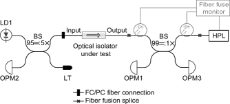
A fiber-pigtailed laser diode (LD1, Gooch and Housego AA1406) with - optical power is used to measure the insertion loss of the isolator under test. The transmitted power is measured after 99:1 BS using OPM3 (Thorlabs PM200 with S155C sensor). The insertion loss is then determined by comparing the power measured by OPM3 with the input one, taking into account the additional attenuation from the 99:1 BS. Our setup is equipped with a fiber fuse monitor, which shutdowns the high-power laser automatically in case the fiber fuse is detected, preventing an extensive damage of equipment Huang et al. (2020). Fortunately, the fiber fuse has not occurred during the tests reported in this article. Moreover, a temperature map of the samples is measured by a thermal imaging camera (Fluke TiS45), which is placed over the samples and saves thermal images every during each experiment. It is notable that during the testing on ISO PM1 as an initial trial, there is no thermal images recording yet.
II.2 Experimental setup for testing circulators
To determine the testing setup for fiber-optic circulators, we shall first discuss two configurations that a three-port circulator can have in the QKD system. In the first scenario, the circulator is employed to direct Alice’s optical pulses Lucio-Martinez et al. (2009); Tang et al. (2014); Wang et al. (2016); Xia et al. (2019); Liu et al. (2019). That is, the optical pulses first pass from port 1 to port 2. Then the pluses are reflected back to port 2 and transmitted to port 3 as the output of the QKD sender. Thus, the isolation values between each port pair matter to the security of the QKD system. In the second scenario, the circulator is used to monitor the injected light Mo et al. (2005); Wang et al. (2014). If the injected light is detected by a monitor connected at port 3, Alice and Bob may interrupt their QKD session without secret key leakage. However, it has been shown that the laser-damage attack might decrease the sensitivity of the monitor Makarov et al. (2016) and the high-speed optical pulses might bypass the alarming mechanism of the monitor Sajeed et al. (2015b). In this case, the success of the light-injection attack will highly rely on the monitor’s properties and signal processing, instead of the isolation provided by the circulator, which is out of the scope of the present study.
As discussed above, in this study we focus on testing the isolation characterization of circulator configured in the first scenario, while testing the whole configuration in this scenario will be the future work. The experimental setup of testing the circulator is shown in Fig. 2. The measurement settings at ports 1 and 3 are the same as described hereinabove for isolator testing in Sec. II.1. In addition to that, a laser diode (LD2, Gooch and Housego AA1406) and an optical power meter (OPM4, Thorlabs PM200 with S154C sensor) are placed at port 2 via a 50:50 BS. LD1, LD2, and the HPL are used one at a time to prevent measurement errors caused by reflected light. Isolation and insertion loss are estimated for each pair of circulator’s ports via a procedure similar to that described in Sec. II.1.

II.3 Test procedure
Before starting the test on the optical isolators and circulators, we experimentally verified that up to none of the components in the setup, excluding the optical isolators and circulators, change their characteristics during the test. Especially, the splitting ratios of BS are not seen notably change. Thus, the only changes observed in the following test are in the isolators and circulators under test.
We define a successfully “hacked” isolation component as one having a temporal or permanent isolation decrease without losing light transmission capability in the forward direction, within our measurement accuracy of about . We also notice when the insertion loss increases permanently. Such an increase would lead (with a threshold that depends on the particular QKD system) to the secret key failing to be generated. This means the eavesdropper would not be able to learn any secret information.
The test procedure is the following for each component under test. Firstly, the initial isolation and insertion loss are measured in the experimental setup before illumination by HPL. Then each sample is exposed to a constant power level starting from for at least (except for the sample ISO PM 1, which is exposed for at least as the initial test). The exposure period may be increased up to during the testing if necessary. During the illumination, the isolation of the isolator under test is monitored. For circulators, the isolation values from port 3 to port 1 and from port 3 to port 2 are measured during the illumination. If isolation reduction is detected, the laser power is kept constant until the isolation value becomes stable. After each round of illumination, the HPL is turned off, and we measured the insertion loss of the sample under test again. For isolators, LD1 is turned on, and the insertion loss is measured by OPM3. For circulators, LD1 and LD2 are turned on alternately, and insertion loss from port 1 to port 2 and from port 2 to port 3 is measured by OPM4 and OPM3. In addition, LD2 are also used to measure the isolation from port 2 to port 1 with assistance of OPM2. The temporary changes in isolation and insertion loss are recorded during the measurement.
We repeat the testing procedure above with laser power of the HPL incremented by –. The testing stops if an irreversible damage to the sample is incurred. For some samples, the testing stops before the sample is fully damaged. This is because we would like to measure the permanent decrease in isolation, while the sample is still operational.
III Results
III.1 Test results for fiber-optic isolators
| Sample | Specified minimum isolation () | Initial | Minimum isolation () | Maximum decrease of isolation () | Irreversible damage at | |
| Insertion loss () | Isolation () | |||||
| ISO PM 1 | 46 | 0.66 | 53.7 | 21.8 @ , | 31.9 | , |
| ISO PM 2 | 28 | 0.50 | 37.0 | 17.2 @ , | 19.8 | was not tested |
| ISO 3-1 | 46 | 0.45 | 58.1 | 37.1 @ , | 21.0 | was not tested |
| ISO 3-2 | 46 | 0.55 | 62.1 | 27.6 @ , | 34.5 | , |
| ISO 4 | 55 | 0.52 | 57.6 | 42.4 @ , | 15.2 | was not tested |
We have tested four models of fiber-optic isolators used in real QKD systems: one sample of models 1, 2 and 4 (ISO PM 1, ISO PM 2, and ISO 4) and two samples of isolator model 3 (ISO 3-1 and ISO 3-2). All the isolators have a similar design and operation principle except that ISO PM 1 and ISO PM 2 are polarization-dependent, while the other two models are polarization-insensitive. According to their specifications, all the tested isolators should operate correctly at a maximum c.w. power of , except for ISO PM 2, whose maximum operating power is . The operating temperature range of all the samples is to . Owing to our confidentiality agreements with the QKD system manufacturers, we cannot publicly disclose the part numbers of the components tested in this study. They are ordinary commercial off-the-shelf products.
A summary of the laser-damage results is presented in Table 1. The tested samples are vulnerable to the high-power injection laser, exhibiting the temporary reduction of isolation by – at a certain illumination power (see “Maximum decrease of isolation” in Table 1). As a result, – isolation remains before samples become inoperable (see “Minimum isolation”), which is less than every sample’s specified minimum isolation value. In addition, ISO PM 1 and ISO 3-2 are destroyed at and injected laser power applied for and respectively. Detailed results of the testing are given in Fig. 3.
The characteristics of ISO PM 1 differ significantly from the other samples because of the shorter laser exposure time at the beginning of its test, which is not enough to observe significant changes in isolation. However, when the exposure period is lasting longer with optical power higher than , the decrease in isolation is illustrated.
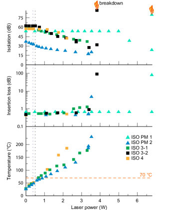
As can be seen from the topmost plot in Fig. 3, the isolation reduction under high-power laser is observed for all the samples. It does not happen until the applied laser power exceeds the maximum operating power specified by the manufacturer, except for ISO PM 2, for which isolation reduction from its maximum value by was observed in the operating power range. However, even for this sample, the measured isolation conforms to the specification when the illumination laser power is in the operating range (specified minimum isolation of ISO PM 2 is , see Table 1). The “breakdown” points in Fig. 3 indicate that ISO PM 1 and ISO 3-2 are fully damaged at the laser power of and —they exhibit extremely large insertion loss and isolation. For the other samples, we stopped the laser exposure before completely destroying them, observing a permanent decrease in isolation by for ISO PM 2 and temporary decrease in isolation for ISO 3-1 and ISO 4.
Interestingly, before being destroyed, the isolators keep operating in the forward direction (see their insertion loss values in the middle plot in Fig. 3) while their isolation values are reduced. The insertion loss varies slightly by –, which leads to the loss of only 22% forward transmitted power at most. Once the irreversible damage happens for ISO PM 1 and ISO 3-2, their insertion loss is larger than .
The sample’s surface temperature (see the bottommost plot in Fig. 3) rises with the illumination power. It seems to be related to the isolation value. The isolation of the polarization-insensitive samples ISO 3-1 and ISO 4 begins dropping when their measured temperature exceeds the maximum specified operating temperature of .
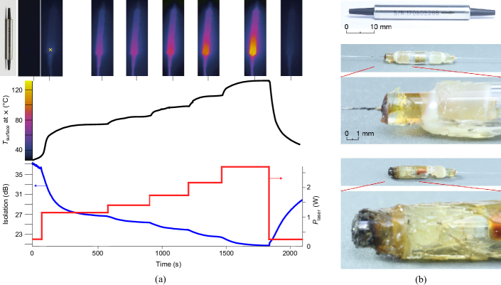
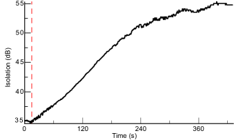
In order to understand the mechanism of isolation decrease and isolators’ damage, we analyze the thermal images and disassemble the tested samples as shown in Fig. 4. Figure 4(a) illustrates the surface temperature maps, the temperature curve, and the isolation curve of ISO PM 2 in one experiment. The thermal profile of the isolator under a high-power laser shows that the sample is heated inhomogeneously across its surface. Specifically, the tested sample is heated at the side opposite to the input port where the high-power laser is applied, which is also observed in all the other tested samples. This is because the injected high-power laser emission is rejected to be coupled from the isolator to the optical fiber Berent et al. (2013), and next, the rejected light is absorbed inside the package to cause this local heating.
Moreover, after applying laser power higher than the sample’s specified maximum operating value (), the amount of isolation drops rapidly with the power. After cooling, the isolation reverts close to the initial value. Figure 4(b) shows the external and internal design of the tested samples, ISO 3-1 and ISO 3-2. After the disassembly of the sample, we found a destroyed blackened side of the optical assembly, which matches the point of the highest surface temperature marked in the thermal images. Thus, we infer that high temperature causes this destruction.
To further verify the cause of isolation change, we theoretically simulate the working model of an isolator with details given in Appendix A. There, we have calculated temperature dependence of Verdet constant and isolation changes for a single-stage polarization-dependent isolator. The analysis shows that the polarization rotation angle depends on temperature. As a result, when the temperature becomes high, the light injected in the backward direction is not fully reflected by the isolator’s polarizer but is partially transmitted. Thus, the amount of isolation is reduced under high temperature. These modeling results correlate well with the experimental data of ISO PM 2, which may provide a reasonable explanation of the decrease in isolation observed in our experiment.
| Initial | ||||||||||
| Sample | Specified minimum isolation for all ports () | Insertion loss () | Isolation () | Minimum isolation () | Maximum decrease of isolation () | Irreversible damage at | ||||
| 1 to 2 | 2 to 3 | 2 to 1 | 3 to 2 | 2 to 1 | 3 to 2 | 2 to 1 | 3 to 2 | |||
| CIR 1 | 45 | 1.03 | 1.07 | 61.4 | 60.6 | 34.7 @ | 32.2 @ | 26.7 | 28.4 | was not tested |
| CIR 2 | 40 | 0.72 | 0.83 | 67.0 | 65.7 | 38.3 @ | 32.3 @ | 28.7 | 33.4 | , |
| CIR PM 3 | 25 | 1.00 | 0.80 | 37.0 | 27.0 | was not tested | 6.4 @ | was not tested | 20.6 | , |
III.2 Test results for fiber-optic circulators
We have tested three fiber-optic circulators. Samples of CIR 1 and CIR 2 are polarization-insensitive, while CIR PM 3 is polarization-dependent. Similar to the isolators, the specified operating power is for CIR 1 and CIR 2 ( for CIR PM 3), and the operating temperature range is from 0 to .
A summary of our testing results is given in Table 2. The isolation is temporarily reduced not only between the ports illuminated by the laser (from port 3 to port 2) but also between the unilluminated ports (from port 2 to port 1). Specifically, the isolation from port 3 to port 2 (port 2 to port 1) decreases by – (–) at maximum. The residual isolation is – from port 3 to port 2 and – from port 2 to port 1, which is lower than the minimum isolation specified by the component manufacturer for all the samples. Thus, the transmission paths from port 1 to port 2 and from port 2 to port 3 are vulnerable to Eve’s high-power injection attack.
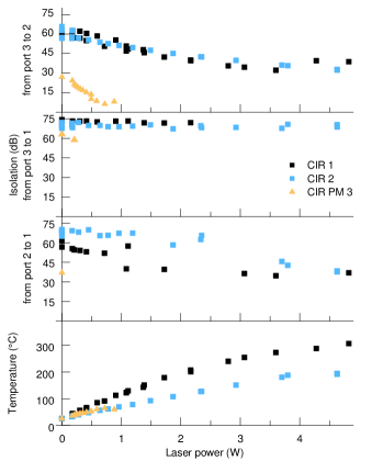
The detailed measurement data are presented in Fig. 5, showing isolation from port 3 to port 2, from port 3 to port 1, and from port 2 to port 1, as well as the maximum surface temperature under different illumination powers. The values of isolation from port 3 to port 2 and port 2 to port 1 are obviously decreased with the increased laser power, as the coupling ratio mainly depends on the polarization rotation provided by a Faraday mirror inside the circulator. However, the isolation from port 3 to port 1 remains essentially unchanged under all experimental conditions for all the tested samples, which is due to no coupling between these two ports according to the internal scheme. Similar to the isolators under test, the temperature of the sample’s surface also rises with the laser power.
For both polarization-insensitive samples, the minimum remaining isolation from port 3 to port 2 is (CIR 1) and (CIR 2) at the laser power of and respectively. After that, the isolation value rises for CIR 1, and we thus stop our testing of it at the laser power of without observing an irreversible damage. Meanwhile, irreversible damage happens for CIR 2 with the increase in its insertion loss to from port 2 to port 3 at .
Moreover, for each of these two samples, we have measured the isolation from port 2 to port 1 immediately after the laser exposure and found that the sample’s heating also temporarily reduces it. Take CIR 1 as an example. Figure 6 illustrates its recovery after the laser exposure, in which the value of isolation reduces to about once after being illuminated by the HPL. After the HPL is switched off, the isolation then recovers to in , during which the sample’s surface temperature decreases from to .
Surprisingly, for the polarization-sensitive sample, CIR PM 3, the isolation from port 3 to port 2 falls rapidly with the increased laser power, dropping to only at the input laser power of . At , the insertion loss from port 2 to port 3 increases irreversibly to . Since port 2 and port 3 of this sample is supposed to be used in the QKD system purely as an isolator, we have not measured the change in the insertion loss from port 1 to port 2, isolation from port 2 to port 1, and isolation from port 3 to port 1.
IV Discussion and countermeasures
The experimental results shown above provide two opposite insights into the security of a QKD system. We first discuss the hacking aspect about the vulnerabilities in a QKD system caused by the isolation reduction of the tested isolators and circulators. Then, from the defence point of view, we propose a possible countermeasure to protect the QKD source from these vulnerabilities.
The isolation reduction introduced by high-power laser opens loopholes for at least two possible attacks on QKD, the Trojan-horse attack Gisin et al. (2006); Jain et al. (2014) and the laser-seeding attack Huang et al. (2019); Sun et al. (2015); Pang et al. (2020). Regarding the Trojan-horse attack, the isolation of the source strongly impacts the secure key rate and transmission distance. The reduced isolation of the source allows Eve to inject more Trojan-horse light into Alice, which is assumed to linearly increases the reflection light. Given – decrease in isolation obtained from our testing results, the photon number of reflection pulse increases by about – orders from the safe value. These amounts of increase in leaked photon number result in the maximum transmission distance shortens by – according to the various, theoretical security analysis Lucamarini et al. (2015); Tamaki et al. (2016); Wang et al. (2018); Álvaro Navarrete and Curty .
Regarding the laser-seeding attack, an injection power in the order of after passing the built-in isolator of Alice’s laser to reach the laser cavity is sufficient for achieving a successful attack Huang et al. (2019). According to our experimental result, the maximum power transmitted through the isolation component is , assuming the injected power is Huang et al. (2020) and the isolation is reduced to as in ISO PM 2. (Although the minimum value of isolation obtained in our experiment is for CIR PM 2, we exclude this type of circulator from the analysis owing to its poor performance and we do not recommend it for use in QKD systems.) To prevent the laser-seeding attack, other components in QKD source should provide about of isolation. Assuming the built-in isolation of the laser is typically , the success of the laser-seeding attack relies on the attenuation value of an optical attenuator in Alice. If the attenuation value is less than , the security of the QKD system might be compromised under laser-seeding attack. It is notable that in the above analysis, we assume that the attenuator in Alice works as designed, which does not affect the effectiveness of above-mentioned attacks. Regarding to the possible vulnerability of attenuators, the decreased attenuation under laser-damage attack has been investigated in Ref. Huang et al., 2020.
Most importantly, our study also provides a possible countermeasure against the light-injection attacks—adding an extra isolation component into the source unit to be the first one illuminated by the injected light. Its minimum residual isolation upper-bounds the maximum power that can transmit through to reach other optical components. Specifically, the minimum observed isolation is and for the polarization-dependent circulator CIR PM 3 and isolator ISO PM 2, respectively. Typical minimum residual isolation is more than for all the polarization-insensitive components. Therefore, the injected power is limited to less than , which cannot successfully conduct the laser-damage attack on any optical components according to the previous testing Bugge et al. (2014); Makarov et al. (2016); Huang et al. (2020). If the attacker attempts to further increase the illumination power, the first component fails permanently with a very high insertion loss, which results in a denial of service and thus protects the QKD system from the leakage of secret information Makarov et al. (2016). Moreover, the isolation required for protection against the Trojan-horse attack and the laser-seeding attack should be calculated starting from the component behind this sacrificial isolator or circulator. Therefore, the extra isolator or circulator placed at Alice’s output would protect the rest of the QKD source against the light-injection attacks.
V Conclusion
In this paper, we study the effect of high-power laser on the fiber-optics isolators and circulators and propose the effective countermeasure against light-injection attacks on a QKD system. This study first raises awareness of insecure isolation components—isolators and circulators—in QKD systems. Specifically, the testing shows that the values of isolation provided by the optical isolators and circulators under test are reduced to and at minimum when high-power laser light is injected into them in the reverse direction. This decrease of isolation opens loopholes, which may allow Eve to conduct the Trojan-horse attack, the laser-seeding attack, and possibly other attacks that inject light into the source. The testing methodology proposed in this study is general and applicable to the other commercial fiber-optic isolators and circulators. To enhance the protection of the QKD source unit, an extra isolation component, an optical isolator or circulator, is needed to defeat the light-injection attacks. The residual isolation of this extra component is sufficient to protect the other components behind it. Any isolation calculated for countermeasure against the Trojan-horse attack and the laser-seeding attack shall be started from the components behind this sacrificial isolation component. Our study shows that the source unit in the QKD system needs this additional layer of protection to be secure.
Acknowledgements.
We thank K. Wei, F. Xu, and our industry partners for providing us device samples. This work was funded by the Ministry of Science and Education of Russia (programs 5-in-100, NTI center for quantum communications, and grant 075-11-2021-078), Russian Science Foundation (grant 21-42-00040), Canada Foundation for Innovation, MRIS of Ontario, the National Natural Science Foundation of China (grants 61901483 and 62061136011), the National Key Research and Development Program of China (grant 2019QY0702), and the Research Fund Program of State Key Laboratory of High Performance Computing (grant 202001-02). P.C. acknowledges support from the DPST scholarship and NSRF via the Program Management Unit for Human Resources & Institutional Development, Research and Innovation (grant B05F640051). Author contributions: A.P., D.R., V.E., A.H., and P.C. conducted the experiment. A.P., D.R., V.E., A.H., and V.M. analysed the data. A.P., D.R., and A.H. wrote the article with help from all authors. A.H. and V.M. supervised the project.Appendix A Theoretical temperature dependence of the Verdet constant and isolation in fiber-optic isolators
A.0.1 Faraday effect in a polarization-dependent isolator
An optical isolator is a component that only allows unidirectional transmission of the optical signal. The principal scheme of polarization-dependent isolator is shown in Fig. A.1. It consists of an input polarizer, a Faraday rotator, and an output polarizer called an analyzer. The optical axis of the second polarizer is oriented at an angle with respect to the first polarizer. In this configuration, the optical signal coming from the left side passes through the first polarizer whose optical axis is in the vertical direction, which matches the polarization of the input optical signal. Then a Faraday rotator rotates the polarization of the optical signal by in a clockwise direction. If there is an introduced laser beam from the optical circuit on the right side, this optical signal has to pass through the Faraday rotator from right to left. Since the Faraday rotator is a non-reciprocal device, the polarization state of the reflected optical signal will rotate for an additional in the same direction as the input signal, thus becoming perpendicular to the optical axis of the first polarizer.
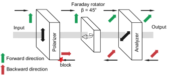
As shown above, an optical isolator is based on the Faraday effect Zvezdin and Kotov (1997). The polarization plane of linearly polarized light beam during propagation in a magneto-optical crystal is rotated by an angle . The direction of rotation is dependent on the direction of the magnetic field and not on the direction of light propagation. The relation between the angle of polarization rotation and the magnetic field in a crystal is
| (A.1) |
where is the longitudinal magnetic field component in, is the length of the path where the light and magnetic field interact in, and is the Verdet constant depending on the wavelength of the propagating light and temperature of magneto-optic crystal in /. Here we shall consider only the temperature dependence.
The temperature dependence of Verdet constant and hence the angle of Faraday rotation leads to variation of the isolation coefficient with temperature. Modern single-mode isolators have a high stability of isolation in the temperature range from to . Thermal effects can be neglected for typical optical circuits, such as QKD systems, with laser power less than –. However, when the high-power laser is applied in the reverse direction, its emission is partially absorbed inside the isolator and induces heating of the magneto-optic crystal Kiriyama et al. (2015). The temperature dependence of the Verdet constant causes the changes of the angle of polarization plane rotation [see Eq. A.1] Snetkov et al. (2014); Khazanov (2016). For optical isolators, it means reducing the isolation coefficient in the reverse direction and losing power and degraded beam quality in the forward direction. Thermal effects can be mitigated by a careful choice of the magneto-optical material in the component Snetkov et al. (2014). The most widespread materials for a single-stage fiber isolator in near infrared band are rare-earth garnets Booth and White (1984); Mukimov et al. (1990); Khazanov (2016). Here we consider the following types of garnets: yttrium iron garnet (YIG), terbium gallium garnet (TGG), and bismuth-substituted yttrium iron garnet (Bi:YIG).
A.0.2 Verdet constant model
In a general case, the Verdet constant of rare-earth garnet is impacted by several different contributions Slezák et al. (2016); Serber (1932); Buckingham and Stephens (1966). In our case, only temperature-dependent contributions are considered: the paramagnetic contribution (for more detail see Ref. Vojna et al., 2018) and frequency-independent gyromagnetic term (detail in Ref. Zvezdin and Kotov, 1997). The Verdet constant as a function of temperature has the appearance
| (A.2) |
where is the wavelength of dominant electronic transition, is the Curie temperature, and , , are constants depending on the properties of chosen material.
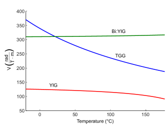
Using data from Refs. Vojna et al., 2018; Zhao, 2019; Cooper et al., 1968; Crossley et al., 1969; Stevens et al., 2016; Matsumoto and Suzuki, 1986; Vertruyen et al., 2008; Vojna et al., 2019; Kumari and Chakraborty, 2018, the dependence of the Verdet constant is obtained within a temperature range from to , as presented in Fig. A.2. These dependencies have been calculated with fixed operating wavelength . As reflected in Fig. A.2, the crystal TGG has exhibited the least stability with temperature. This means that isolators based on TGG are most susceptible to thermal effects at . Isolators based on YIG or Bi:YIG should be more temperature-stable.
A.0.3 Isolation model
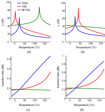
Next, we analyze the change in isolation with varying crystal temperature in the proposed model with the ideal polarizer and analyzer. The polarization planes of the polarizer and the analyzer are oriented relative to each other at the angle , and Faraday rotator provides the rotation of the polarization plane of the propagating light with a central wavelength of . In our model, the magnetic field is constant and independent of temperature (but in real systems magnetic field might introduce changes in isolation). According to Malus’s law, after passing through Faraday rotator and the polarizer, the intensity of a beam of plane-polarized light varies as , where is the initial intensity Booth and White (1984); Vojna et al. (2018). The isolation coefficient is then defined as . (The insertion loss may be found from the similar formula using rotation angles equal to .) After substituting the value of from Eq. A.1, the temperature dependence of the isolation coefficient takes the form
| (A.3) |
where is the coefficient depending on the initial isolation value at the temperature of kon . Let’s use the initial isolation value of , as a typical value for single-stage isolators at room temperature ranges from to according to their specification kon . The isolation of corresponds to the rotation angle of polarization plane in the Faraday rotator either or , depending on the direction of rotation. The calculation results for isolation and insertion loss are presented in Fig. A.3.
The model predicts sharp peaks in the isolation value. It should be noted that generally there are no pronounced peaks in our experimental results of the isolation coefficient when the components being heated by the laser. This may be explained by the internal scattering in the crystal, which leads to a partial change in the plane of polarization. However, this factor is not considered in this model.
A.0.4 Outcome
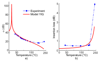
Our model shows that the change of the isolation coefficient with temperature depends heavily on the material of the magneto-optical crystal, even though each garnet may provide the same isolation value at room temperature. The crystal TGG has demonstrated the sharpest decrease in the isolation coefficient in the operating temperature range of isolators. This is because the operating wavelength range for this garnet is from to Vojna et al. (2018). The Bi:YIG crystal is specially designed for applications demanding high values of the isolation coefficient over a wide temperature range Kiriyama et al. (2015); Vojna et al. (2019). According to the calculation, the isolation coefficient is more than in the temperature range from to . Such a high isolator stability is achieved due to the optimal crystal composition Zhao (2019). Additional doping provides several sublattices in the crystal structure, which compensate the temperature dependence of the Verdet constant (and isolation respectively) of each other. In YIG, our model predicts that the isolation decreases by about at . When temperature increases significantly (up to ), isolation drops to about . The obtained result fits well with the experimental data for ISO PM 2. The comparison of experiment with model is shown in Fig. A.4.
In summary, our model shows that Bi:YIG has the weakest dependence of the isolation coefficient on temperature and therefore it is the most advanced garnet for the isolators resilient to the laser-damage attack. In addition, we may assume that the magneto-optic crystal in the isolator ISO PM 2 is YIG.
References
- Bennett and Brassard (1984) C. H. Bennett and G. Brassard, “Quantum cryptography: Public key distribution and coin tossing,” in Proc. International Conference on Computers, Systems, and Signal Processing (Bangalore, India) (IEEE Press, New York, 1984) pp. 175–179.
- Ekert (1991) A. K. Ekert, “Quantum cryptography based on Bell’s theorem,” Phys. Rev. Lett. 67, 661–663 (1991).
- Gisin et al. (2002) N. Gisin, G. Ribordy, W. Tittel, and H. Zbinden, “Quantum cryptography,” Rev. Mod. Phys. 74, 145–195 (2002).
- Scarani et al. (2009) V. Scarani, H. Bechmann-Pasquinucci, N. J. Cerf, M. Dušek, N. Lütkenhaus, and M. Peev, “The security of practical quantum key distribution,” Rev. Mod. Phys. 81, 1301 (2009).
- Lo et al. (2014) H.-K. Lo, M. Curty, and K. Tamaki, “Secure quantum key distribution,” Nat. Photonics 8, 595–604 (2014).
- Xu et al. (2020) Feihu Xu, Xiongfeng Ma, Qiang Zhang, Hoi-Kwong Lo, and Jian-Wei Pan, “Secure quantum key distribution with realistic devices,” Rev. Mod. Phys. 92, 025002 (2020).
- Arute et al. (2019) F. Arute, K. Arya, R. Babbush, D. Bacon, J. C. Bardin, R. Barends, R. Biswas, Sergio Boixo, Fernando GSL Brandao, D. A. Buell, B. Burket, Y. Chen, Z. Chen, C. Chiaro, R. Colins, W. Courtney, A. Dunsworth, E. Farhi, B. Foxen, A. Fowler, C. Gidney, M. Giustina, R. Graff, K. Gerin, S. Hebegger, M. H. Harrigan, M. J. Hartman, A. Ho, M. Hoffman, T. Huang, Trevis S Humble, S. V. Isakov, E. Jeffrey, Z. Jiang, D. Kafri, K. Kechendzhi, J. Kelly, P. V. Klimov, S. Knysh, A. Kiritkov, F. Kostritsa, D. Landhuis, M. Lindermark, E. Lucero, D. Lyakh, S. Mandrà, J. R. McClean, M. McEwen, A. Megrant, X. Mi, K. Michielsen, M. Mohseni, J. Mutus, O. Naaman, M. Neeley, C. Niel, M. Y. Niu, E. Ostby, A. Petukhov, J. C Platt, C. Quintana, E. G. Rieffel, P. Roushan, N. C. Rubin, D. Sank, K. J. Satzinger, V. Smelyanskiy, K. J. Sung, M. D. Trevitchick, A. Vainsencher, B. Villalonga, T. White, Z. Yao, J. M. Neven, and J. M. Martinis, “Quantum supremacy using a programmable superconducting processor,” Nature 574, 505–510 (2019).
- Makarov et al. (2006) V. Makarov, A. Anisimov, and J. Skaar, “Effects of detector efficiency mismatch on security of quantum cryptosystems,” Phys. Rev. A 74, 022313 (2006), erratum ibid. 78, 019905 (2008).
- Qi et al. (2007) B. Qi, C.-H. F. Fung, H.-K. Lo, and X. Ma, “Time-shift attack in practical quantum cryptosystems,” Quantum Inf. Comput. 7, 73–82 (2007).
- Lamas-Linares and Kurtsiefer (2007) A. Lamas-Linares and C. Kurtsiefer, “Breaking a quantum key distribution system through a timing side channel,” Opt. Express 15, 9388–9393 (2007).
- Lydersen et al. (2010a) L. Lydersen, C. Wiechers, C. Wittmann, D. Elser, J. Skaar, and V. Makarov, “Hacking commercial quantum cryptography systems by tailored bright illumination,” Nat. Photonics 4, 686–689 (2010a).
- Lydersen et al. (2010b) L. Lydersen, C. Wiechers, C. Wittmann, D. Elser, J. Skaar, and V. Makarov, “Thermal blinding of gated detectors in quantum cryptography,” Opt. Express 18, 27938–27954 (2010b).
- Xu et al. (2010) F. Xu, B. Qi, and H.-K. Lo, “Experimental demonstration of phase-remapping attack in a practical quantum key distribution system,” New J. Phys. 12, 113026 (2010).
- Li et al. (2011) Hong-Wei Li, Shuang Wang, Jing-Zheng Huang, Wei Chen, Zhen-Qiang Yin, Fang-Yi Li, Zheng Zhou, Dong Liu, Yang Zhang, Guang-Can Guo, Wan-Su Bao, and Zheng-Fu Han, “Attacking a practical quantum-key-distribution system with wavelength-dependent beam-splitter and multiwavelength sources,” Phys. Rev. A 84, 062308 (2011).
- Wiechers et al. (2011) C. Wiechers, L. Lydersen, C. Wittmann, D. Elser, J. Skaar, C. Marquardt, V. Makarov, and G. Leuchs, “After-gate attack on a quantum cryptosystem,” New J. Phys. 13, 013043 (2011).
- Lydersen et al. (2011a) L. Lydersen, M. K. Akhlaghi, A. H. Majedi, J. Skaar, and V. Makarov, “Controlling a superconducting nanowire single-photon detector using tailored bright illumination,” New J. Phys. 13, 113042 (2011a).
- Lydersen et al. (2011b) L. Lydersen, N. Jain, C. Wittmann, Ø. Marøy, J. Skaar, C. Marquardt, V. Makarov, and G. Leuchs, “Superlinear threshold detectors in quantum cryptography,” Phys. Rev. A 84, 032320 (2011b).
- Gerhardt et al. (2011) I. Gerhardt, Q. Liu, A. Lamas-Linares, J. Skaar, C. Kurtsiefer, and V. Makarov, “Full-field implementation of a perfect eavesdropper on a quantum cryptography system,” Nat. Commun. 2, 349 (2011).
- Sun et al. (2011) S.-H. Sun, M.-S. Jiang, and L.-M. Liang, “Passive Faraday-mirror attack in a practical two-way quantum-key-distribution system,” Phys. Rev. A 83, 062331 (2011).
- Jain et al. (2011) N. Jain, C. Wittmann, L. Lydersen, C. Wiechers, D. Elser, C. Marquardt, V. Makarov, and G. Leuchs, “Device calibration impacts security of quantum key distribution,” Phys. Rev. Lett. 107, 110501 (2011).
- Bugge et al. (2014) A. N. Bugge, S. Sauge, A. M. M. Ghazali, J. Skaar, L. Lydersen, and V. Makarov, “Laser damage helps the eavesdropper in quantum cryptography,” Phys. Rev. Lett. 112, 070503 (2014).
- Sajeed et al. (2015a) S. Sajeed, P. Chaiwongkhot, J.-P. Bourgoin, T. Jennewein, N. Lütkenhaus, and V. Makarov, “Security loophole in free-space quantum key distribution due to spatial-mode detector-efficiency mismatch,” Phys. Rev. A 91, 062301 (2015a).
- Huang et al. (2016a) A. Huang, S. Sajeed, P. Chaiwongkhot, M. Soucarros, M. Legré, and V. Makarov, “Testing random-detector-efficiency countermeasure in a commercial system reveals a breakable unrealistic assumption,” IEEE J. Quantum Electron. 52, 8000211 (2016a).
- Makarov et al. (2016) V. Makarov, J.-P. Bourgoin, P. Chaiwongkhot, M. Gagné, T. Jennewein, S. Kaiser, R. Kashyap, M. Legré, C. M., and S. Sajeed, “Creation of backdoors in quantum communications via laser damage,” Phys. Rev. A 94, 030302 (2016).
- Huang et al. (2018) A. Huang, S.-H. Sun, Z. Liu, and V. Makarov, “Quantum key distribution with distinguishable decoy states,” Phys. Rev. A 98, 012330 (2018).
- Qian et al. (2018) Yong-Jun Qian, De-Yong He, Shuang Wang, Wei Chen, Zhen-Qiang Yin, Guang-Can Guo, and Zheng-Fu Han, “Hacking the quantum key distribution system by exploiting the avalanche-transition region of single-photon detectors,” Phys. Rev. Appl. 10, 064062 (2018).
- Huang et al. (2019) A. Huang, Á. Navarrete, S.-H. Sun, P. Chaiwongkhot, M. Curty, and V. Makarov, “Laser-seeding attack in quantum key distribution,” Phys. Rev. Appl. 12, 064043 (2019).
- Huang et al. (2020) A. Huang, R. Li, V. Egorov, S. Tchouragoulov, K. Kumar, and V. Makarov, “Laser damage attack against optical attenuators in quantum key distribution,” Phys. Rev. Appl. 13, 034017 (2020).
- Sun and Huang (2022) Shihai Sun and Anqi Huang, “A review of security evaluation of practical quantum key distribution system,” Entropy 24, 260 (2022).
- Chaiwongkhot et al. (2022) Poompong Chaiwongkhot, Jiaqiang Zhong, Anqi Huang, Hao Qin, Sheng-cai Shi, and Vadim Makarov, “Faking photon number on a transition-edge sensor,” EPJ Quantum Technol. 9, 23 (2022).
- (31) Anqi Huang, Akihiro Mizutani, Hoi-Kwong Lo, Vadim Makarov, and Kiyoshi Tamaki, “Characterisation of state preparation uncertainty in quantum key distribution,” arXiv:2205.11870 [quant-ph] .
- (32) Binwu Gao, Zhihai Wu, Weixu Shi, Yingwen Liu, Dongyang Wang, Chunlin Yu, Anqi Huang, and Junjie Wu, “Strong pulse illumination hacks self-differencing avalanche photodiode detectors in a high-speed quantum key distribution system,” arXiv:2205.04177 [quant-ph] .
- Lo et al. (2012) H.-K. Lo, M. Curty, and B. Qi, “Measurement-device-independent quantum key distribution,” Phys. Rev. Lett. 108, 130503 (2012).
- Lucamarini et al. (2018) M. Lucamarini, Z. L. Yuan, J. F. Dynes, and A. J. Shields, “Overcoming the rate–distance limit of quantum key distribution without quantum repeaters,” Nature 557, 400 (2018).
- Wang et al. (2022) Shuang Wang, Zhen-Qiang Yin, De-Yong He, Wei Chen, Rui-Qiang Wang, Peng Ye, Yao Zhou, Guan-Jie Fan-Yuan, Fang-Xiang Wang, Wei Chen, Yong-Gang Zhu, Pavel V. Morozov, Alexander V. Divochiy, Zheng Zhou, Guang-Can Guo, and Zheng-Fu Han, “Twin-field quantum key distribution over 830-km fibre,” Nat. Photonics 16, 154–161 (2022).
- Bennett (2017) C. Bennett, “The slippery slope between quantum information and public information, and why cheap DIY randomness is better than expensive DI randomness,” (2017) QCrypt 2017 rump session, http://2017.qcrypt.net/events-in-qcrypt-2017/rump-session/.
- Gisin et al. (2006) N. Gisin, S. Fasel, B. Kraus, H. Zbinden, and G. Ribordy, “Trojan-horse attacks on quantum-key-distribution systems,” Phys. Rev. A 73, 022320 (2006).
- Jain et al. (2014) N. Jain, E. Anisimova, I. Khan, V. Makarov, Ch. Marquardt, and G. Leuchs, “Trojan-horse attacks threaten the security of practical quantum cryptography,” New J. Phys. 16, 123030 (2014).
- Sun et al. (2015) S.-H. Sun, F. Xu, M.-S. Jiang, X.-C. Ma, H.-K. Lo, and L.-M. Liang, “Effect of source tampering in the security of quantum cryptography,” Phys. Rev. A 92, 022304 (2015).
- Pang et al. (2020) X.-L. Pang, A.-L. Yang, C.-N. Zhang, J.-P. Dou, H. Li, J. Gao, and X.-M. Jin, “Hacking quantum key distribution via injection locking,” Phys. Rev. Appl. 13, 034008 (2020).
- Sajeed et al. (2015b) Shihan Sajeed, Igor Radchenko, Sarah Kaiser, Jean-Philippe Bourgoin, Anna Pappa, Laurent Monat, Matthieu Legré, and Vadim Makarov, “Attacks exploiting deviation of mean photon number in quantum key distribution and coin tossing,” Phys. Rev. A 91, 032326 (2015b).
- Mo et al. (2005) X.-F. Mo, B. Zhu, Z.-F. Han, Y.-Z. Gui, and G.-C. Guo, “Faraday-Michelson system for quantum cryptography,” Opt. Lett. 30, 2632–2634 (2005).
- Huang et al. (2016b) D. Huang, P. Huang, D. Lin, and G. Zeng, “Long-distance continuous-variable quantum key distribution by controlling excess noise,” Sci. Rep. 6, 19201 (2016b).
- Wang et al. (2016) J. Wang, X. Qin, Y. Jiang, X. Wang, L. Chen, F. Zhao, Z. Wei, and Z. Zhang, “Experimental demonstration of polarization encoding quantum key distribution system based on intrinsically stable polarization-modulated units,” Opt. Express 24, 8302–8309 (2016).
- Dixon et al. (2017) A. R. Dixon, J. F. Dynes, M. Lucamarini, B. Fröhlich, A. W. Sharpe, A. Plews, W. Tam, Z.-L. Yuan, Y. Tanizawa, H. Sato, S. Kawamura, M. Fujiwara, M. Sasaki, and A. J. Shields, “Quantum key distribution with hacking countermeasures and long term field trial,” Sci. Rep. 7, 1978 (2017).
- Xia et al. (2019) X.-X. Xia, Z. Zhang, H.-B. Xie, X. Yuan, J. Lin, S.-K. Liao, Y. Liu, C.-Z. Peng, Q. Z., and J.-W. Pan, “LED-based fiber quantum key distribution: toward low-cost applications,” Photonics Res. 7, 1169–1174 (2019).
- Wei et al. (2020) K. Wei, W. Li, H. Tan, Y. Li, H. Min, W.-J. Zhang, H. Li, L. You, Z. Wang, X. Jiang, T.-Y. Chen, S.-K. Liao, C.-Z. Peng, F. Xu, and J.-W. Pan, “High-speed measurement-device-independent quantum key distribution with integrated silicon photonics,” Phys. Rev. X 10, 031030 (2020).
- Liu et al. (2019) H. Liu, Z.-W. Yu, M. Zou, Y.-L. Tang, Y. Zhao, J. Zhang, X.-B. Wang, T.-Y. Chen, and J.-W. Pan, “Experimental 4-intensity decoy-state quantum key distribution with asymmetric basis-detector efficiency,” Phys. Rev. A 100, 042313 (2019).
- Lucamarini et al. (2015) M. Lucamarini, I. Choi, M. B. Ward, J. F. Dynes, Z. L. Yuan, and A. J. Shields, “Practical security bounds against the Trojan-horse attack in quantum key distribution,” Phys. Rev. X 5, 031030 (2015).
- (50) Work Programme of GS QKD 010 Quantum Key Distribution (QKD), Implementation security protection against Trojan horse attacks in one-way QKD systems, https://portal.etsi.org/webapp/workProgram/Report_Schedule.asp?WKI_ID=43375, visited 5 May 2014.
- Lucio-Martinez et al. (2009) I. Lucio-Martinez, P. Chan, X. Mo, S. Hosier, and W. Tittel, “Proof-of-concept of real-world quantum key distribution with quantum frames,” New J. Phys. 11, 095001 (2009).
- Tang et al. (2014) Zhiyuan Tang, Zhongfa Liao, Feihu Xu, Bing Qi, Li Qian, and Hoi-Kwong Lo, “Experimental demonstration of polarization encoding measurement-device-independent quantum key distribution,” Phys. Rev. Lett. 112, 190503 (2014).
- Wang et al. (2014) Shuang Wang, Wei Chen, Zhen-Qiang Yin, Hong-Wei Li, De-Yong He, Yu-Hu Li, Zheng Zhou, Xiao-Tian Song, Fang-Yi Li, Dong Wang, Hua Chen, Yun-Guang Han, Jing-Zheng Huang, Jun-Fu Guo, Peng-Lei Hao, Mo Li, Chun-Mei Zhang, Dong Liu, Wen-Ye Liang, Chun-Hua Miao, Ping Wu, Guang-Can Guo, , and Zheng-Fu Han, “Field and long-term demonstration of a wide area quantum key distribution network,” Opt. Express 18, 21739–21756 (2014).
- Berent et al. (2013) Michał Berent, Andon A. Rangelov, and Nikolay V. Vitanov, “Broadband faraday isolator,” J. Opt. Soc. Am. A 30, 149–153 (2013).
- Tamaki et al. (2016) Kiyoshi Tamaki, Marcos Curty, and Marco Lucamarini, “Decoy-state quantum key distribution with a leaky source,” New J. Phys. 18, 065008 (2016).
- Wang et al. (2018) Weilong Wang, Kiyoshi Tamaki, and Marcos Curty, “Finite-key security analysis for quantum key distribution with leaky sources,” New J. Phys. 20, 083027 (2018).
- (57) Álvaro Navarrete and Marcos Curty, “Improved finite-key security analysis of quantum key distribution against trojan-horse attacks,” arXiv:2202.06630v1 [quant-ph] .
- Zvezdin and Kotov (1997) A. K. Zvezdin and V. A. Kotov, Modern Magnetooptics and Magnetooptical Materials, Condensed Matter Physics (CRC Press, 1997).
- Kiriyama et al. (2015) H. Kiriyama, M. Mori, A. S. Pirozhkov, K. Ogura, A. Sagisaka, A. Kon, T. Z. Esirkepov, Y. Hayashi, H. Kotaki, M. Kanasaki, H. Sakaki, Y. Fukuda, J. Koga, M. Nishiuchi, M. Kando, S. V. Bulanov, K. Kondo, P. R. Bolton, O. Slezak, D. Vojna, M. Sawicka-Chyla, V. Jambunathan, A. Lucianetti, and T. Mocek, “High-contrast, high-intensity petawatt-class laser and applications,” IEEE J. Sel. Top. Quantum Electron. 21, 232–249 (2015).
- Snetkov et al. (2014) I. L. Snetkov, A. V. Voitovich, O. V. Palashov, and E. A. Khazanov, “Review of Faraday isolators for kilowatt average power lasers,” IEEE J. Quantum. Electron. 50, 434–443 (2014).
- Khazanov (2016) E. A. Khazanov, “Thermooptics of magnetoactive media: Faraday isolators for high average power lasers,” Phys. Uspekhi 59, 886–909 (2016).
- Booth and White (1984) R. C. Booth and E. A. D. White, “Magneto-optic properties of rare earth iron garnet crystals in the wavelength range 1.1–1.7 m and their use in device fabrication,” J. Phys. D: Appl. Phys. 17, 579–587 (1984).
- Mukimov et al. (1990) K. M. Mukimov, B. Yu. Sokolov, and U. V. Valiev, “The Faraday effect of rare-earth ions in garnets,” Phys. Status Solidi A 119, 307–315 (1990).
- Slezák et al. (2016) O. Slezák, R. Yasuhara, A. Lucianetti, and T. Mocek, “Temperature-wavelength dependence of terbium gallium garnet ceramics Verdet constant,” Opt. Mater. Express 6, 3683–3691 (2016).
- Serber (1932) R. Serber, “The theory of the Faraday effect in molecules,” Phys. Rev. 41, 489–506 (1932).
- Buckingham and Stephens (1966) A. D. Buckingham and P. J Stephens, “Magnetic optical activity,” Annu. Rev. Phys. Chem. 17, 399–432 (1966).
- Vojna et al. (2018) David Vojna, Ryo Yasuhara, Hiroaki Furuse, Ondrej Slezak, Simon Hutchinson, Antonio Lucianetti, Tomas Mocek, and Miroslav Cech, “Faraday effect measurements of holmium oxide (Ho2O3) ceramics-based magneto-optical materials,” High Power Laser Sci. Eng. 6, e2 (2018).
- Zhao (2019) Weizhong Zhao, “Magneto-optic properties and sensing performance of garnet YbBi:YIG,” Sens. Actuator A Phys. 89, 250–254 (2019).
- Cooper et al. (1968) R. W. Cooper, W. A. Crossley, J. L. Page, and R. F. Pearson, “Faraday rotation in YIG and TbIG,” J. Appl. Phys. 39, 565–567 (1968).
- Crossley et al. (1969) W. A. Crossley, R. W. Cooper, J. L. Page, and R. P. van Stapele, “Faraday rotation in rare-earth iron garnets,” Phys. Rev. 181, 896–904 (1969).
- Stevens et al. (2016) G. Stevens, T. Legg, and P. Shardlow, “Integrated disruptive components for fibre lasers (ISLA): project overview and passive component development,” in Components and Packaging for Laser Systems II, Vol. 9730, edited by Alexei L. Glebov and Paul O. Leisher, International Society for Optics and Photonics (SPIE, 2016) pp. 1–6.
- Matsumoto and Suzuki (1986) S. Matsumoto and S. Suzuki, “Temperature-stable Faraday rotator material and its use in high-performance optical isolators,” Appl. Opt. 25, 1940–1945 (1986).
- Vertruyen et al. (2008) B. Vertruyen, R. Cloots, J. S. Abell, T. J. Jackson, R. C. da Silva, E. Popova, and N. Keller, “Curie temperature, exchange integrals, and magneto-optical properties in off-stoichiometric bismuth iron garnet epitaxial films,” Phys. Rev. B 78, 094429 (2008).
- Vojna et al. (2019) D. Vojna, O. Slezák, A. Lucianetti, and T. Mocek, “Verdet constant of magneto-active materials developed for high-power Faraday devices,” Appl. Sci. 9, 3160 (2019).
- Kumari and Chakraborty (2018) S. Kumari and S. Chakraborty, “Study of different magneto-optic materials for current sensing applications,” J. Sens. Sens. Syst. 7, 421–431 (2018).
- (76) Y. Konno and H. Kume, “Optical isolator and method for assembling same,” US patent US5204868A, granted 1993-04-20.