Lightweight Object-level Topological Semantic Mapping and Long-term Global Localization based on Graph Matching
Abstract
Mapping and localization are two essential tasks for mobile robots in real-world applications. However, large-scale and dynamic scenes challenge the accuracy and robustness of most current mature solutions. This situation becomes even worse when computational resources are limited. In this paper, we present a novel lightweight object-level mapping and localization method with high accuracy and robustness. Different from previous methods, our method does not need a prior constructed precise geometric map, which greatly releases the storage burden, especially for large-scale navigation. We use object-level features with both semantic and geometric information to model landmarks in the environment. Particularly, a learning topological primitive is first proposed to efficiently obtain and organize the object-level landmarks. On the basis of this, we use a robot-centric mapping framework to represent the environment as a semantic topology graph and relax the burden of maintaining global consistency at the same time. Besides, a hierarchical memory management mechanism is introduced to improve the efficiency of online mapping with limited computational resources. Based on the proposed map, the robust localization is achieved by constructing a novel local semantic scene graph descriptor, and performing multi-constraint graph matching to compare scene similarity. Finally, we test our method on a low-cost embedded platform to demonstrate its advantages. Experimental results on a large scale and multi-session real-world environment show that the proposed method outperforms the state of arts in terms of lightweight and robustness.
I Introduction
Mobile robots have gained impressive developments in various fields over the past decades. Robust mapping and localization are critical prerequisites for the long-term autonomous navigation of mobile robots. The most important solution is to establish an effective global consistency description of the environmental information, and simultaneous localization [1]. Classical metric maps build high precise geometric model of environment and clearly correspond to the real world, which based on SLAM technology.
With these metric maps, mobile robots obtain precise localization and navigation. However, the expensive computation, incremental accumulation errors and vast storage of metric maps challenge its geometrical consistency and make it’s more difficult to maintain the accuracy of the map. Especially, this task can be particularly complex when done online on a robot with limited computing capabilities and storage resources [2]. Thus, robust and lightweight mapping and localization is of special interest for both academic and industry research.
For the above problems, the topological approach provides a lightweight mapping solution similar as simple and compact, scale better and require much less space to be stored than metric map [3]. Despite of their remarkable results, there still some challenges in topological mapping methods. For example, pure topological map is not sufficient for robot navigation, which calls for metric information. Besides, most existing methods build the topological graph based on the global consistent metric map. They don’t avoid the disadvantages of metric map completely. These above reasons motivate us to design a real lightweight and robust mapping and navigation method. These two tasks become particularly challenging when the environmental condition changes due to dynamic people, objects, and/or when the scale of the environment becomes very large.
LiTang et al. proposed a topological local-metric framework in which the global coordinates does not exist to achieve long term mapping and localization [4]. However, its integrated visual appearance-based loop closure method reduces robustness to environmental changes. Recently, semantic graph description provides an effective method for accurate and robust localization. Existing work [5] [6] [7] [19] have explored that high level semantic features provide a more robust representation for the scene since they incorporate the information of objects’ own properties and their mutual relations. They are able to cope with the global localization under extreme appearance changes successfully [5].
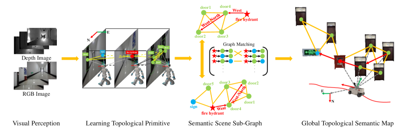
In this paper, we combine the above advantages to realize a lightweight mapping that organizes the semantic and geometric properties of environmental objects through topological graph, and completes a robust localization based on semantic graph description of the local scene, we calls it an Object-level Topological Semantic Map(OLTSM). An overview of the framework is shown in Fig 1. OLTSM represents an environment as a lightweight abstract graph, topological nodes are object-level landmarks, and topological edges are described using the semantic association properties between object-level landmarks. Extract semantic features of objects and relative semantic associations between objects in a visual odometry (VO)-like manner by means of defined learning topology primitives. Particularly, inspired by the way humans navigate, we build a map with the robot ontology as the coordinate origin, to control the offset error between local neighboring nodes. Meanwhile, a hierarchical memory management strategy was introduced to improve the efficiency of online mapping. Furthermore, we introduced an object-level semantic graph descriptor and a semantic graph matching method to achieve robust localization. Last but not least, the algorithm was deployed to a low-cost embedded platform and tested it in the muilt-session real world.
The main contributions are summarized as follows:
-
•
An online lightweight mapping solution based on semantic associations of objects and topological organization is proposed. This map is built in a robot-centric human-like navigation way.
-
•
A localization method based on object-level semantic scene graph matching is proposed, which is robust to variations in dynamic environmental such as viewpoint and illumination.
-
•
Online mapping and localization based on OLTSM is realized on the low-cost embedded platform.
-
•
Experimental results validate the effectiveness of our methods. Our approach greatly outperforms classical metric mapping methods in terms of lightweight. And also the proposed method obtains higher robustness than the method based on visual appearance information in long-term dynamic situations.
II Related Work
In this section, we review the related work on mapping and localization methods.
For mapping, classical metric mapping methods have reached maturity by accurately encoding the geometric 3D information about the environment. However, these methods still face challenges for long-term navigation in large, unstructured and dynamic environments. For above reason, topology maps are widely explored to represent the environment in abstract graphs, achieving a simple and compact lightweight representation while control the error between local adjacent nodes [8] [9] [10] [11]. However, the solution is not suitable for robot navigation that requires metric guidance [4]. Therefore, the one idea is the construction of highly consistent topological representations based on metric mappings [9] [10]. Although it makes the map lightweight, it also limits the high scalability of topological maps and is not easily applicable to long-term navigation. The other idea is incorporating accurate local metric information in topological representations [4] [11]. However, local matching localization using image level is still not sufficiently robust when the environment changes. Moreover, due to the widespread successful application of deep learning, the learning-based approach has also attracted a lot of interest [12] [13]. It relies on a large number of labeled datasets and cannot be applied well to an unfamiliar environment.
For localization, the existing methods of localization can be divided into two major categorys, based on visual appearance information or spatial relationships of landmarks. In the last decade, a large number of methods based on visual appearance information have been proposed that give reliable performance under perceptually similar conditions [14] [15]. To futher improve accuracy and robustness, several extensions have been proposed. The one idea is to extract and describe visual features by using convolutional neural networks (CNN) [16]. However, when the viewpoint change becomes significant, these visual landmarks also become unreliable. The other idea is to integrate semantic and appearance information [17] [18] [19]. However, they focused on reducing drift using image-based associations, our approach tend to perform localization through a graph-based semantic local environmant representation model. Another localization methods by using the spatial relationship of surrounding landmarks to represent, such as the graph-based methods [5] [6] [7]. Futhermore, random walk [5] [21], graph kernel [20], histogram [7] and graph embedding [6] algorithms are widely used to extract the information of the graph structure and perform similarity matching. YuLiu et al. proposed to utilize graph matching and 3D alignment into a object-level global localization algorithm [21]. It was demonstrated that graph-based object-level semantic information descriptors which can improve the localization performance.
Driven by above methods and inspired by the navigation behaviors of human being, in this letter, we intend to incorporate the semantic and geometric information into the graph structure. Then, the similarity calculation between semantic scene graphs is realized by graph matching.
III Lightweight Object-level Topological Semantic Map
The map is a fundamental representation of interest (e.g., landmarks, obstacles) describing the environment in which the robot operates [21]. Inspired by the way humans navigate, we pay more attention to recent relative movements than to the global position for long-term navigation. Therefore, in this paper, we represent the environment by using a lightweight abstract topology graph that records the relative associations between objects. The basic structure of this map is a graph defined as , where and denote the nodes and edges of the graph, respectively. On this basis, A robot-centric global-free pose map is constructed using topological organization. In particular, semantic features of objects and data associations between objects are extracted though a VO-like process, which we define as learning topological primitives. The details are described as follows.
III-A Topological Map Representation
In this section, we first introduce the concrete representation of the constructed abstract graph as follows. The representation of the map is shown in the semantic scene sub-graph in Fig 2.
III-A1 Node Representation
In this paper, we take the objects in the scene as topological nodes and define the nodes with the semantic properties of the objects themselves, such as class, color, etc. Thus, for each node belonging to , the corresponding properties are defined as . is the serial number added to the graph in order. is the coordinate of the object center point obtained by fusing deep imfromation. is defined as a proxy for additional properties of the node. For example, functional and operational properties, and 6D pose (position and orientation), etc. Peculiarly, to achieve an exact match between them, different with hand designed descriptor, we propose a novel multiple attribute semantic descriptor for object-level nodes including semantic, geometric center, and object-level semantic scene graph with topological organization. The semantic scene graph descriptors are obtained as described in Section \@slowromancapiv@.A.
III-A2 Edge Representation
For topological edges, the associated object-level node relative relationship attributes are used to define, for example, the relative direction and distance between nodes. Thus, for each edge , connecting the neighboring nodes and , belonging to , the corresponding properties are defined as . is a rigid relative distance between node and , which is also used as the weight of the topology graph. It can be obtained in creating the map from a variety of sources, such as sensor measurements and human measurements. is a relative direction between node and in the geomagnetic coordinate system. we introduce IMU to calculate the magnetic declination angle. is defined as a proxy for additional properties of the edge.
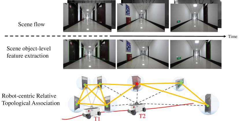
III-B Robot-centric Relative Topological Association
The purpose of this section is to perform scene object feature extraction and relative topological association for constructing object-level abstract topology graphs. For this purpose, we propose a learning topological primitive , which is defined to implement learning-based object feature extraction with fusion of spatial and semantic information and topology-based data association through a VO-like process in a stream of scenes during a continuous time period . The formula is represented as follows:
| (1) |
Then, we refine the relative association between objects by the principle of vector coordinate invariance. The left half of Fig 2 shows the VO-like process from visual environment perception to learning topological primitive construction.
III-B1 Learning Topological Primitive
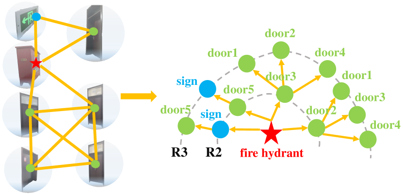
With the robot moves in scene flow, in this letter, we first extract semantic information about the environment’s objects based on the lightweight 2D object detection method YOLOv5111https://github.com/ultralytics/yolov5 that achieves advanced performance. We choose long-term static objects that are more aligned with human navigation road signs as valid landmarks, such as door, fire hydrant, pillar etc. In addition, since the 3D center point of an object is subject to less affected variation in viewpoint, we implemented 3D center point detection based on the object 2D detection box by adding depth information.
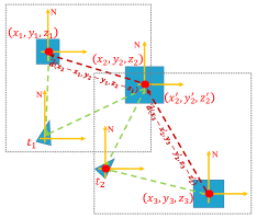
Afterwards, the relative positions between objects in the scene flow are associated in a robot-centric topology. The association of environmental topology information is shown in Fig 3.a. In the constructed topological map, we use the robot ontology as the coordinate origin, and by transforming the nodes and the robot ontology coordinates, the relative direction between adjacent nodes is expressed as the direction vector in the calculation. Therefore, any node in the graph and its neighbors maintain only a relative relationship, which reduces the impact of global errors.
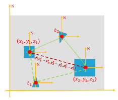
III-B2 Refinement of Relative Topological Association
To ensure effective localization and navigation through the constructed topological semantic map without global poses, we propose a strategy based on the principle of vector coordinate invariance to refine the relative positions between objects by transforming the robot body coordinates to geomagnetic coordinates. Since the direction of the geomagnetic coordinate system is usually constant, based on the principle of coordinate invariance of vectors, the relationship between adjacent fixed nodes does not change with time and space, as is shown in Fig 3.b. The specific implementation of the pseudocode is shown in Algorithm 1.
(a)
(b)
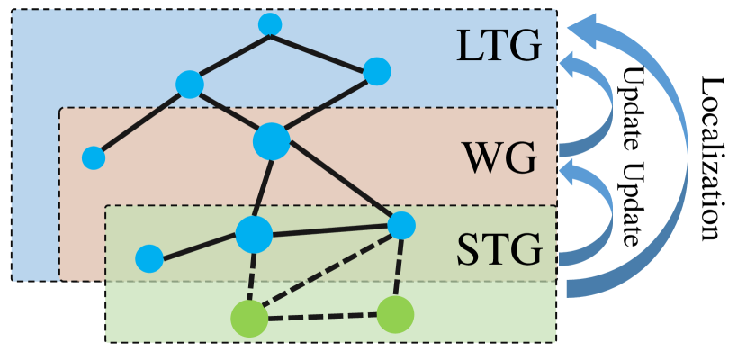
III-C Hierarchical Memory Management
Finally, to improve the efficiency of online mapping with limited computing resources, in this section, we have introduced a hierarchical memory management mechanism, which reduces the retrieved area through a bottom-up hierarchical matching update strategy. Thus, the memory management is divided into three hierarchicals in this paper: Short-Term Graph (STG), Working Graph (WG) and Long-Term Graph (LTG), as shown by Fig 4. STG is a bottom temporary local sub-graph constructed from previously added nodes and objects in the current frame sequence, being fixed to 5 nodes. WG is a middle-level local subgraph constructed by randomly walking around with a radius of three steps with the node in STG as the root node. LTG is a top-level global graph that has been constructed. To satisfy online map updata, by leveraging the graph matching method proposed in Section \@slowromancapiv@ to quickly match the local semantic scene subgraphs STG and WG, STG nodes that are not in the WG (nodes in STG but not in WG) will be added to the LTG, and new spatial semantic association information is constructed. In addition, when a re-localization is required, by matching STG and LTG, we can also determine the current location of the robot in the LTG.
IV Localization with object-level semantic scene graph matching
Localization is widely acknowledged as crucial for robot navigation, especially for long-term navigation. Different from previous geometric solutions, that are less robust to environmental changes, in this section, we present an online topology localization method based on the above constructed map, which is robust to long-term dynamic environmental changes. The details are described as follows.
IV-A Semantic Scene Graph Descriptors
To improve the accuracy and robustness of localization, we have enhanced the description of each node in the graph. Inspired by the [6] graph descriptor, we introduce the random walk descriptor and add semantics and the relative direction information between nodes extracted by learning topological primitives, which implements the object-level semantic scene graph descriptor for the nodes. Specifically, we select the node being described as the root node, and within a certain detection radius, detect and embed all neighboring nodes and the semantic associations between neighboring nodes in a vector group by random walk. The element in the vector represents the object semantic descriptor mentioned above, which consists of the class, color, etc. The element in the vector represents the object direction descriptor, which consists of the relative direction and distance between objects and random walk descriptor of the object. The above steps are performed cyclically by replacing the root node until the graph being described is fully explored. In this paper, the exploration radius for mapping is set as 3 steps, while for localization is 5 steps. The pseudocode of the three-step semantic scene graph descriptor is shown in Algorithm 2. Fig 5 illustrates the process with an example.
IV-B Semantic Scene Graph Matching
In this section, once semantic scene graph descriptors are built for the node, we search associations between query graph and database graph by computing a similarity score between the corresponding graph descriptors to achieve accuracy and robust localization. In this letter, we propose a multi-constraint semantic scene graph similarity matching method, which consists of three parts: Euclidean distance constraint, Confidence constraint and Direction vector constraint.
The euclidean distance constraint of the corresponding node is the first step in the similarity metric, which aims to eliminate the same node in adjacent frames. The euclidean distance is calculated as follows:
| (2) |
Secondly, confidence constraint is mainly to ensure that candidate sequences have consistent class attributes. The confidence constraint for a single random walk path is calculated as follows:
| (3) |
denotes the random walk search radius, denotes the number of overall identifiable object classes, and denotes the object class index number at the th level.
Lastly, the direction vector constraint is mainly by matching the direction of edges between corresponding sequence nodes and by taking the normalized dot product between two descriptors to determine the unique solution. The direction vector cosine of the corresponding edge and the normalized dot product between two descriptors are calculated as follows:
| (4) |
| (5) |
| (6) |
, are the vectors of the corresponding edges in the NED coordinate system with the body as the origin. M,N are the vector groups of these two descriptors respectively. To ensure that the corresponding edges are facing the same way, therefore the direction is greater than or equal to zero.
V Experiment
In this section, we conduct extensive experiments to evaluate the proposed method well. Towards this arm, we first collect 5 challenging real-world indoor datasets. They are captured in a weakly textured indoor long hallway and a large scale complex hospital, as described in section \@slowromancapv@.A. We then evaluate our mapping performance in terms of lightweight and accuracy by comparing with traditional occupied grid map [23] and state-of-the-art sparse point cloud map (ORB-SLAM3 [22]). Finally, we compare our semantic scene graph matching localization method with several appearance-based methods, including traditional and learning methods, to demonstrate the advantages of our method. All experiments are all performed on a consumer-grade NVIDIA Nano ARMv8 Tegra X1 and 4G memory.
V-A Benchmark Dataset
To our knowledge, there does not exist a dataset that meets the requirement of object-level association of our method.
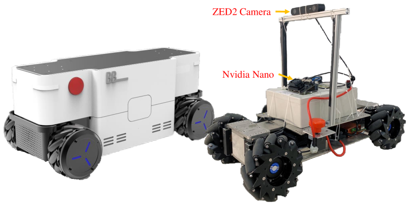
Thus, we create large-scale challenging datasets to . We collected data by using a four-wheeled mobile robot platform equipped with a ZED2222https://www.stereolabs.com/zed-2/ stereo camera, as shown in Fig 6.
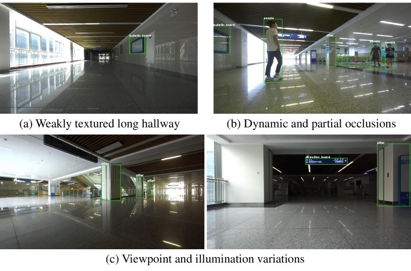
To meet the testing requirements for algorithm, in weakly textured indoor long hallway with 70 meters length, the test dataset was set to four typical scenarios with significant spatial and temporal variability, including multiple time periods, illumination variations, dynamic and partial occlusions, and large viewpoint variations. Details of the long hallway datasets are shown in Table \@slowromancapi@. In complex hospital scenes, over one thousand square meters of scene data were collected. Multiple challenging environmental changes are already available simultaneously in the hospital’s large scenario dataset, as shown in Fig 7.
A total of ten categories of semantic objects are annotated in the two scenes, including doors, fire hydrants, signs, billboards, pillars, chairs, tables, pedestrians, and other objects. Fig 10 and Fig 7 show the semantic objects detected in the long hallway and hospital scenarios, respectively. The dataset is publicly available333https://rec.ustc.edu.cn/share/7a1b2700-2bc7-11ec-ae94-01100e6fec34 password:b52t.
| Challenges* | ||||||
|---|---|---|---|---|---|---|
| Sequences | Data | Tl | Dt | Lv | Iv | Pd |
| LH0** | 21-09-28-10-59 | |||||
| LH1 | 21-09-28-11-04 | |||||
| LH2 | 21-09-28-20-16 | |||||
| LH3 | 21-10-06-11-11 | |||||
| LH4 | 21-10-11-09-34 | |||||
-
*
Tl, Dt, Lv, Iv and Pd are the abbreviation of texture-less, different time period, large viewpoint variation, illumination variationand and pedestrian and partial occlusion, respectively.
-
**
LH0 is the baseline dataset and the rest of the sequences are the test dataset.
V-B Mapping Performance
In this section, we evaluate the performance of the proposed Object-level Semantic Topological Mapping method in terms of lightweight and on collected dataset. Besides, we present the accuracy of our method qualitatively.
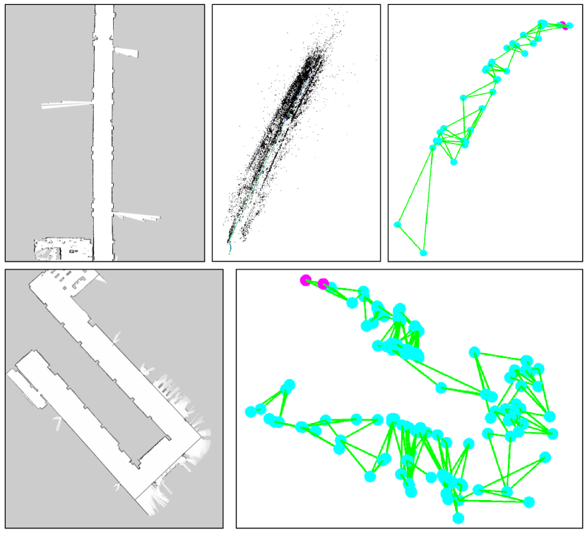
Firstly, to demonstrate the lightweight performance of our mapping method, we compare our object-level semantic topological map with the typical grid map [23] and a state-of-the-art point cloud map [22]. We perform experiments on both long hallway and hospital environment. And we choose storage volume of the map as evaluation metric. The experimental results are shown in Table \@slowromancapii@ and Fig 8. As we can see from the table, in the long corridor scenario only, our map storage is nearly 23 times smaller than the grid map and 310 times smaller than the sparse point cloud map. Thus, the experimental results show the more lightweight performance of the present method. Besides, by comparing the amount of map storage for long corridors and hospital scenarios, we can observe that although the storage space of the map increases as the area increases, our approach greatly reduces the space of map storage and reduces the risk of storage overflow during long-term navigation due to the use of lightweight topology to build the map.
| Ours | Grid map | ORB-SLAM3 | |
|---|---|---|---|
| Long hallway | 66.4Kb | 1.52Mb | 20.6Mb |
| Hospital | 233.7Kb | 3.51Mb | –Mb |
Secondly, the time analysis of the main time-consuming parts of the whole system is shown in Table \@slowromancapiii@. The time consuming part of object detection contains the acquisition of semantic information about the object and the computation of 3D centroids. The speedup is approximately ten times compared to the traditional visual feature point extraction. As we can see from the table, although the addition of semantic objects increases the computational burden of the system, our mapping system can still run online.
| Module | Time(ms/frame) |
|---|---|
| Object Extraction | 89 |
| Descriptor Extraction | 0.58 |
| Graph Matching | 0.89 |
| Total | 90.47 |
Finally, to further evaluate the accuracy of the maps, we mapped the constructed robot-centric topological semantic maps to the odometer coordinate system by coordinating transformation and compared them with wheeled odometers. The experimental results in the long hallway and hospital scenarios are shown in Fig 9. It can be seen from the figure that the constructed map basically matches the trajectory of the odometer, which verifies the accuracy of the map.
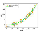
(a) Long hallway scenes
(b) Hospital scenes
V-C Long-term Localization Performance
In this section, to better identify the strengths and weakness of our semantic scene graph matching based localization method, we comparing it with several leading appearance-based localization methods in the collected long-term dynamic scenarios.
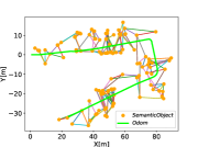
To illustrate the advantages of the our algorithm, firstly, we performed two feature matching experiments in three challenging scenes (viewpoint change, lighting change, and dynamic objects), as is shown in Fig 10. The three columns in the lower left corner are the detection results based on the traditional ORB features. From the figure, we can see that the accuracy of the method is susceptible to environmental changes and cannot effectively perform scene similarity matching. However, we can observe that the semantic mapping matching-based approach has better robustness to larger differences in environmental changes.
(a) LH0-LH2, Day and night time periods
(b) LH0-LH3, Illumination variation
(c) LH0-LH4, Pedestrian and partial occlusion
(d) LH0-LH1, Large viewpoint variation
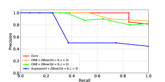
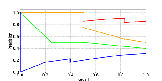
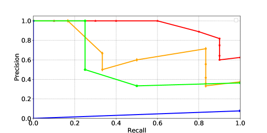
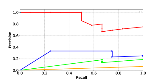
Secondly, we compared it with several appearance-based methods. The first one is a bag of words (BoW) approach using traditional ORB features, built on DBow2444https://github.com/dorian3d/DBoW2 and DBow3555https://github.com/rmsalinas/DBow3 libraries, respectively. The second one is a BoW approach using CNN-based features extraction and description algorithm called Superpoint [16]. In the experiment, Precision-Recall curves (PR-curve) are used to represent the performance of localization. The experimental results are shown in Fig 11. Fig 11.a first shows that several methods have similar accuracy for different time periods only, due to the fact that the less variation of light in the closed indoor environment. However, the accuracy of the appearance-based approach significantly decreased when the lights in the corridor are turned off resulting in changes in illumination, as is shown in Fig 11.b. Particularly, Fig 11.c presents the effect of dynamic objects and partial occlusion on localization, and the results show better robustness of the semantic scene graph matching-based approach, due to the enhanced tolerance to occlusion by the local scene graph descriptors of the objects. What’s more, Fig 11.d further verifies that our method has a significant advantage over appearance-based methods under viewpoint variation. As can be seen from all the subplots, our methods not only have high accuracy, but also have a better recall rate than these appearance-based methods. In addition, even CNN-based methods can be difficult to achieve effective feature extraction and description in difficult structured environments with sparse features and textures. Meanwhile, to show the comparison results of the P-R curves more clearly, we calculated the AUC value of each scene, as is shown in Table \@slowromancapiv@. It proves the robustness of the proposed method further.
| ID | Ours | ORB_DBow2 | ORB_DBow3 | SUP_DBow2 |
|---|---|---|---|---|
| LH1 | 0.59 | 0.13 | 0.28 | 0.57 |
| LH2 | 0.92 | 0.89 | 0.73 | 0.61 |
| LH3 | 0.83 | 0.83 | 0.79 | 0.25 |
| LH4 | 0.86 | 0.73 | 0.72 | 0.37 |
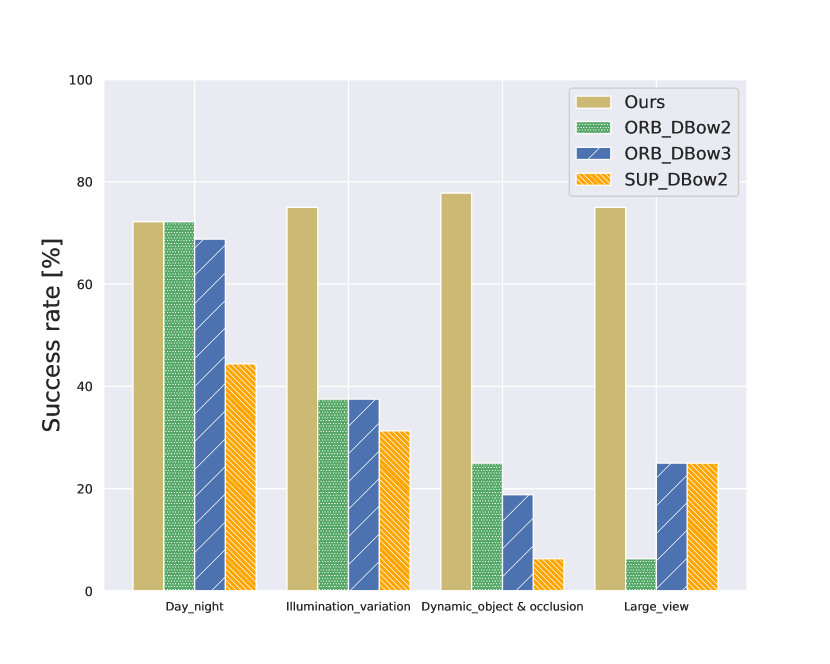
Last but not least, we statistically depicted the success rate of localization in Fig 12. Our method has a higher success rate than appearance-based techniques on multiple datasets and stays close to the 80th percentile.
VI CONCLUSIONS
In this letter, we present a novel lightweight and robust object-level topological semantic mapping and localization framework for long-term navigation. On the one hand, we constructed a lightweight topological semntic map with defined learning topological primitives and hierarchical memory management mechanisms. On the other hand, we achieve robust localization based on improved semantic scene graph descriptors of object and graph matching methods. The framework is evaluated on challenging weakly textured long hallway and large scale hospital scenario datasets, and was run on a low cost embedded computing platform. Experimental results show that the method is sufficiently lightweight and highly robust at large scales, unstructured and long-term dynamic situations and with limited computational resources. In the future we will continue to optimize the performance of mapping and localization, and explore the utilization of constructed maps to perform long-term navigation tasks in real-world scenarios.
References
- [1] Garg, Sourav, et al. ”Semantics for robotic mapping, perception and interaction: A survey.” arXiv preprint arXiv:2101.00443 (2021).
- [2] Labbé, Mathieu, and François Michaud. ”Long-term online multi-session graph-based SPLAM with memory management.” Autonomous Robots 42.6 (2018): 1133-1150.
- [3] Choset, Howie, and Keiji Nagatani. ”Topological simultaneous localization and mapping (SLAM): toward exact localization without explicit localization.” IEEE Transactions on robotics and automation 17.2 (2001): 125-137.
- [4] Tang, Li, et al. ”Topological local-metric framework for mobile robots navigation: a long term perspective.” Autonomous Robots 43.1 (2019): 197-211.
- [5] Qin, Cao, et al. ”Semantic loop closure detection based on graph matching in multi-objects scenes.” Journal of Visual Communication and Image Representation 76 (2021): 103072.
- [6] Gawel, Abel, et al. ”X-view: Graph-based semantic multi-view localization.” IEEE Robotics and Automation Letters 3.3 (2018): 1687-1694.
- [7] Guo, Xiyue, et al. ”Semantic Histogram Based Graph Matching for Real-Time Multi-Robot Global Localization in Large Scale Environment.” IEEE Robotics and Automation Letters (2021).
- [8] Marinakis, Dimitri, and Gregory Dudek. ”Pure topological mapping in mobile robotics.” IEEE Transactions on Robotics 26.6 (2010): 1051-1064.
- [9] Santos-Victor, José, Raquel Vassallo, and Hans Schneebeli. ”Topological maps for visual navigation.” International Conference on Computer Vision Systems. Springer, Berlin, Heidelberg, 1999.
- [10] Talbot, Ben, et al. ”Robot navigation in unseen spaces using an abstract map.” arXiv preprint arXiv:2001.11684 (2020).
- [11] Lui, Wen Lik Dennis, and Ray Jarvis. ”A pure vision-based approach to topological SLAM.” 2010 IEEE/RSJ International Conference on Intelligent Robots and Systems. IEEE, 2010.
- [12] Chaplot, Devendra Singh, et al. ”Neural topological slam for visual navigation.” Proceedings of the IEEE/CVF Conference on Computer Vision and Pattern Recognition. 2020.
- [13] Chaplot, Devendra Singh, et al. ”Learning to explore using active neural slam.” arXiv preprint arXiv:2004.05155 (2020).
- [14] Rublee, Ethan, et al. ”ORB: An efficient alternative to SIFT or SURF.” 2011 International conference on computer vision. Ieee, 2011.
- [15] Gálvez-López, Dorian, and Juan D. Tardos. ”Bags of binary words for fast place recognition in image sequences.” IEEE Transactions on Robotics 28.5 (2012): 1188-1197.
- [16] DeTone, Daniel, Tomasz Malisiewicz, and Andrew Rabinovich. ”Superpoint: Self-supervised interest point detection and description.” Proceedings of the IEEE conference on computer vision and pattern recognition workshops. 2018.
- [17] Yang, Shichao, and Sebastian Scherer. ”CubeSLAM: Monocular 3D object detection and SLAM without prior models.” arXiv preprint arXiv:1806.00557 (2018).
- [18] Salas-Moreno, Renato F., et al. ”Slam++: Simultaneous localisation and mapping at the level of objects.” Proceedings of the IEEE conference on computer vision and pattern recognition. 2013.
- [19] Li, Jimmy, et al. ”View-Invariant Loop Closure with Oriented Semantic Landmarks.” 2020 IEEE International Conference on Robotics and Automation (ICRA). IEEE, 2020.
- [20] Stumm, Elena, et al. ”Robust visual place recognition with graph kernels.” Proceedings of the IEEE Conference on Computer Vision and Pattern Recognition. 2016.
- [21] Liu, Yu, et al. ”Global localization with object-level semantics and topology.” 2019 International Conference on Robotics and Automation (ICRA). IEEE, 2019.
- [22] Campos, Carlos, et al. ”ORB-SLAM3: An Accurate Open-Source Library for Visual, Visual–Inertial, and Multimap SLAM.” IEEE Transactions on Robotics (2021).
- [23] Milstein, Adam. ”Occupancy grid maps for localization and mapping.” Motion planning (2008): 381-408.