A polyconvex transversely-isotropic invariant-based formulation for electro-mechanics: stability, minimisers and computational implementation

Martin Horák111Corresponding author: martin.horak@cvut.cz Antonio J. Gil222Corresponding author: a.j.gil@swansea.ac.uk Rogelio Ortigosa333Corresponding author: rogelio.ortigosa@upct.es Martin Kružík∗,†444Corresponding author: kruzik@utia.cas.cz \dagger Faculty of Civil Engineering, Czech Technical University, Thákurova 7, CZ-166  29 Praha 6, Czech Republic
\ddagger Zienkiewicz Centre for Computational Engineering, Faculty of Science and Engineering
Swansea University, Bay Campus, SA1 8EN, United Kingdom
\starComputational Mechanics and Scientific Computing Group,
Technical University of Cartagena, Campus Muralla del Mar, 30202, Cartagena (Murcia), Spain
\ast Czech Academy of Sciences, Institute of Information Theory and Automation, Pod vodárenskou věží 4, CZ-182 00 Praha 8, Czech Republic
Abstract

The fabrication of evermore sophisticated miniaturised soft robotic components made up of Electro-Active Polymers (EAPs) is constantly demanding parallel development from the in-silico simulation point of view. The incorporation of crystallographic anisotropic micro-architectures, within an otherwise nearly uniform isotropic soft polymer matrix, has shown great potential in terms of advanced three-dimensional actuation (i.e. stretching, bending, twisting), especially at large strains, that is, beyond the onset of geometrical pull-in instabilities. To accommodate for this in-silico response, this paper presents a phenomenological invariant-based polyconvex transversely isotropic framework for the simulation of EAPs at large strains. This research expands previous work developed by Gil and Ortigosa for isotropic EAPs [40] with the help of the pioneering work by Schröeder and Neff [81] in the context of polyconvexity for materials endowed with crystallographic architectures in single physics mechanics. The paper also summarises key important results both in terms of the existence of minimisers and material stability. In addition, a series of numerical examples is presented in order to demonstrate the effect that the anisotropic orientation and the contrast of material properties, as well as the level of deformation and electric field, have upon the response of the EAP when subjected to large three-dimensional stretching, bending and torsion, including the possible development of wrinkling.

keywords:
polyconvexity, transversely isotropic, dielectric elastomers, electro-elasticity, finite element method
journal:

1 Introduction

Electro-Active Polymers (EAPs) are a type of soft smart materials capable of displaying significant change in shape in response to electrical stimuli. EAPs have been thoroughly studied over the years [9, 53, 71, 27] and dielectric elastomers are recognised as one of the most popular EAPs [72, 70, 55] due to their outstanding actuation capabilities555It is worth noting that the maximum achieved voltage-induced area deformation of a dielectric elastomer has been 2200% [4]. (i.e., lightweight, fast response time, flexibility, low stiffness properties), which makes them ideal for their use as soft robots [10, 18, 23, 53, 65, 9, 22, 77, 59], flexible energy generators [63, 54] or tunable optics [5, 75]. However, a large electric field is still generally required in order to access the large actuation regime in EAPs, an aspect that very often places them at risk of electromechanical pull-in instabilities or even electrical breakdown [13].

It was shown in [101] that fibre reinforcement can suppress the electro-mechanical pull-in instability and improve EAPs’ applicability. A dielectric elastomer stiffened with fibers in the hoop direction leading to large, voltage-induced deformations was proposed in [48]. In [44], a voltage-driven deformation of dielectric elastomer reinforced with a family of helical fibres leading to torsional behaviour is studied and the effect of fibre orientation on the actuation of a fibre-reinforced bending actuator is analysed in [1].

In order to reduce the operational voltage required for actuation in EAPs, some authors have advocated for the design of composite-based EAPs [102, 47, 46], typically combining an ultra-soft and low-permittivity elastomer matrix with a stiffer and high-permittivity inclusion [73, 42, 46, 89]. Due to the continuous improvement in layer-by-layer fabrication techniques [36], multi-layered laminated EAP composites have gained popularity. From the modelling point of view, References [58, 57, 28, 92, 38, 39, 92, 27, 13, 76] have demonstrated that the contrast between the properties of the composite constituents is one of their critical design factors, where the actuation performance of an EAP composite subjected to simple in-plane stretching can be amplified by several orders of magnitude with respect to that of a single-phase EAP, even in the linearised regime.

The use of computational methods constructed on the basis of variational principles is nowadays acknowledged as the preferred method for the in-silico simulation of complex actuation. Building upon the works of Toupin [94, 93] and Dorfmann, Ogden, MacMeeking, Suo, and co-workers in [29, 30, 64, 90, 32, 56, 99, 97], recent contributions in the field of computational electro-mechanics can be found in [96, 98, 51, 35, 14]. In these works, the constitutive behaviour of a single-phase electro-mechanical material is encoded within a carefully (phenomenologically) defined energy functional which depends upon appropriate strain measures, a Lagrangian electric variable and, if dissipative effects are considered, an electromechanical internal variable [60]. Bustamante et al. in [20, 21] presents an irreducible invariant basis for transversely isotropic EAPs (without piezoelectric effects) as well as several constitutive restrictions that the final energy density must fulfilled, such as the Baker–Ericksen inequality [21].

However, in order to design and optimise EAPs for a specific application, a robust and reliable physics-based mathematical theory is needed. Despite great recent progress in the field of constitutive modeling of electro-active materials (see above), the polyconvexity condition [7], which represents a sufficient condition for a mathematically well-posed formulation, has been introduced only recently666Note that, in the context of a boundary value problem, polyconvexity together with coercivity guarantees the existence of global minimizers., see [41, 68, 82]. In previous publications [40, 69, 66, 74], the authors put forward a new computational framework for single-phase reversible electro-mechanics, where material stability is always ensured via the selection Convex Multi-Variable (CMV) energy densities, that is, convex with respect to the minors of the deformation gradient tensor (𝑭,𝑯,J)𝑭𝑯𝐽(\boldsymbol{F},\boldsymbol{H},J), the Lagrangian electric displacement 𝑫0subscript𝑫0\boldsymbol{D}_{0}, and the spatial electric displacement 𝒅=𝑭𝑫0𝒅𝑭subscript𝑫0\boldsymbol{d}=\boldsymbol{F}\boldsymbol{D}_{0}. CMV energy densities (generally referred to as polyconvex or 𝒜𝒜\mathcal{A}-polyconvex [85]) guarantee existence of minimisers [85], ellipticity [40] in the quasi-static case and hyperbolicity in the dynamic case [66], thus precluding anomalous mesh dependency effects. The theory of polyconvexity for mechanical anisotropic energy densities was magnificently explored by Schröeder and Neff [81] and it was also initially studied for electro-mechanics anisotropic energies in [50]777However, the differential constraint imposed by the Gauss’s law was not accounted for, leading to an incomplete polyconvexity condition, omitting the coupled electro-mechanical contributions..

As a result, the aim of this paper is three-fold. First, the in-silico modelling of realistic three-dimensional deformation scenarios (namely, combined bending/torsion/stretching), way beyond the onset of geometrical instabilities and without the need to resort to any simplifications in the kinematics of the problem (e.g., plane strain, exact incompressibility). Second, the consideration of internal micro-architectures beyond the simpler single-phase isotropy, with focus on the very relevant transverse isotropy groups, with the idea of developing computationally efficient (phenomenological, invariant-based) constitutive models for EAPs, which could be in the future enriched by state-of-the-art data assimilation techniques  [95]. Third, to ensure the existence and material stability (ellipticity) of computer simulations by unifying and enhancing key results scattered in the literature. From the macroscopic point of view, the loss of ellipticity leads to a mathematically and numerically ill-posed problem that needs to be regularised, e.g., by introducing higher-order derivatives into the constitutive law resulting in the so-called higher-order continua, see [12, 45] for a recently proposed theory of gradient-polyconvexity. Such regularisation is out of the present article’s scope and will be studied in a forthcoming publication.

From the constitutive modelling standpoint, this paper will apply polyconvexity, objectivity, and isotropicisation [86], in order to develop energy densities constructed on the basis of polyconvex invariants forming an irreducible basis for the characterisation of transversely isotropic EAPs. From the numerical implementation standpoint, Finite Element analysis of transversely isotropic EAPs will be presented using an enhanced mixed Hu-Washizu three-field type of formulation (ϕ,𝑫0,φ)bold-italic-ϕsubscript𝑫0𝜑(\boldsymbol{\phi},\boldsymbol{D}_{0},\varphi). The high nonlinearity of the quasi-static electro-mechanical problem will be addressed via a monolithic Newton-Raphson scheme, with an arc length technique used to bypass geometrical instabilities. A tensor cross product operation between vectors and tensors [15, 16] will be used to reduce the complexity of the algebra.

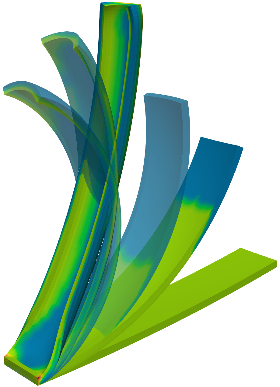
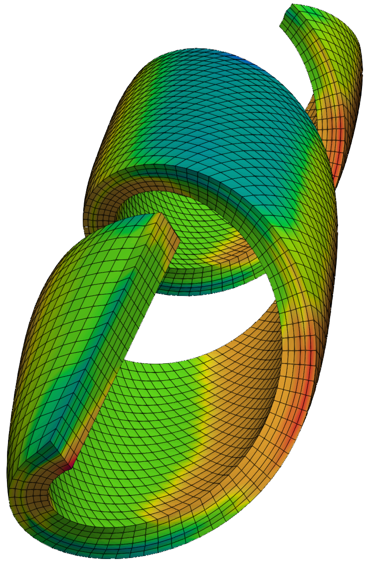
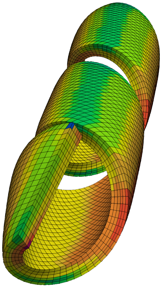
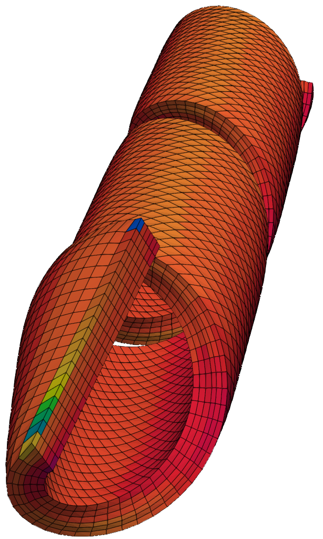
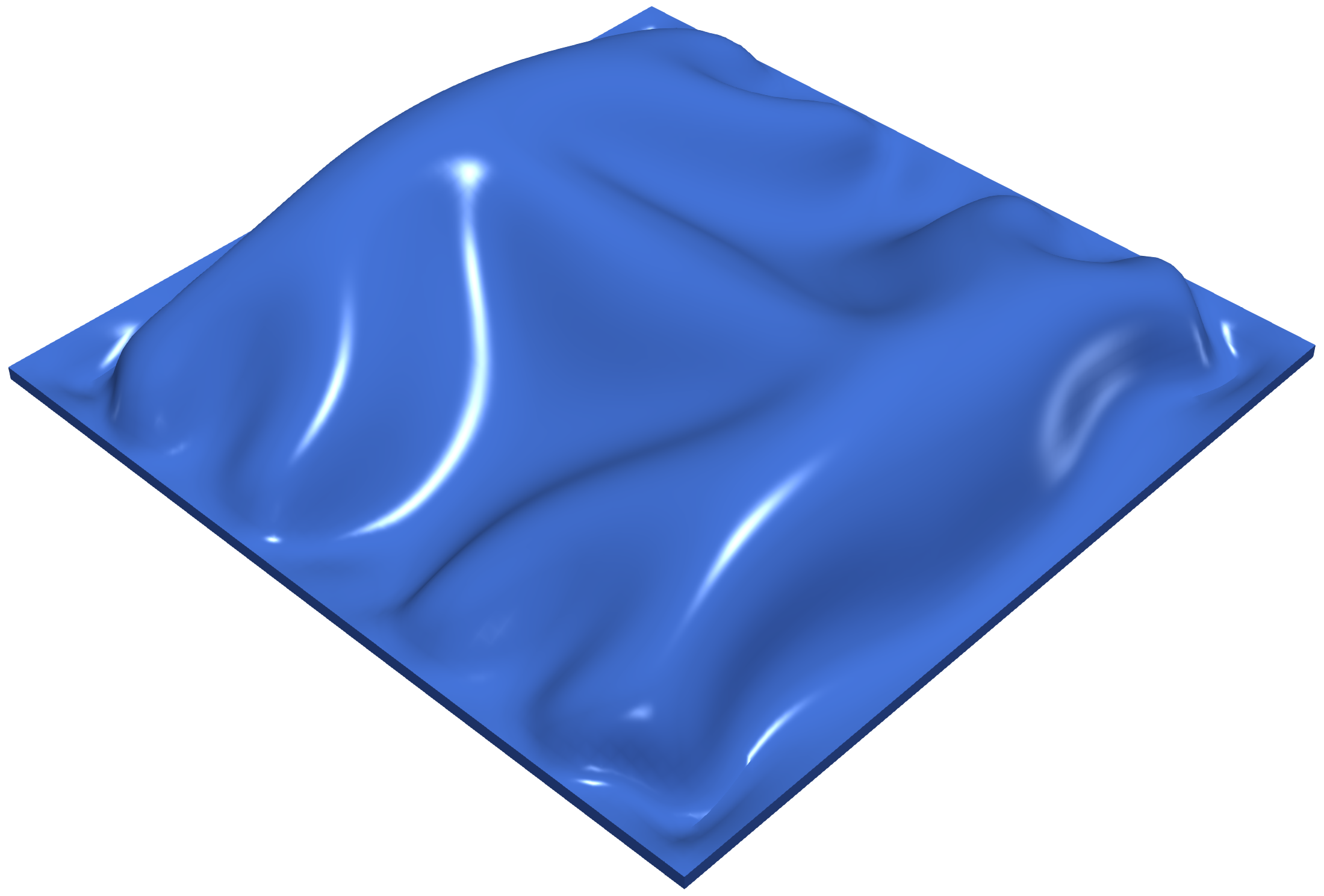
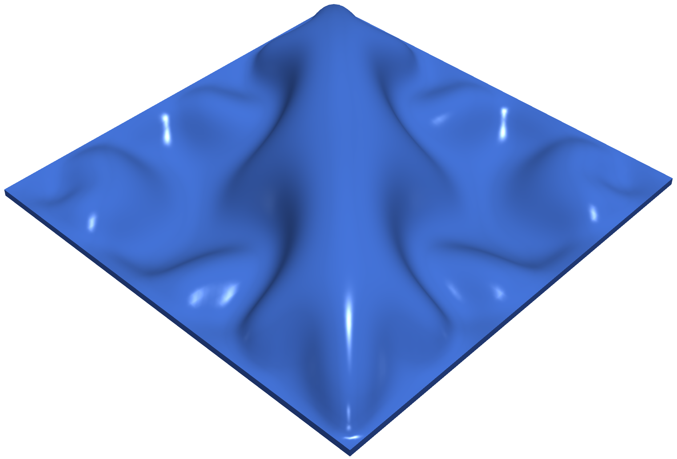
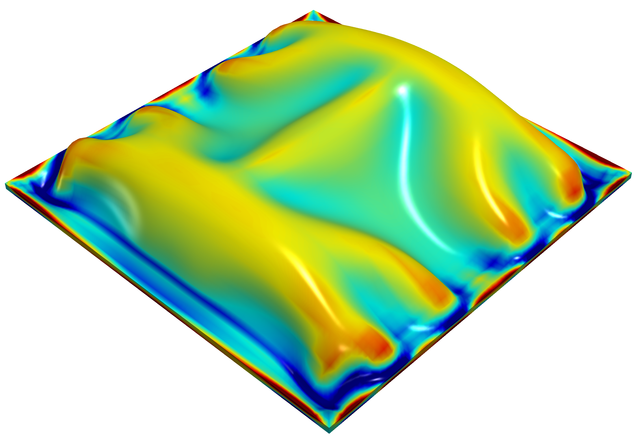
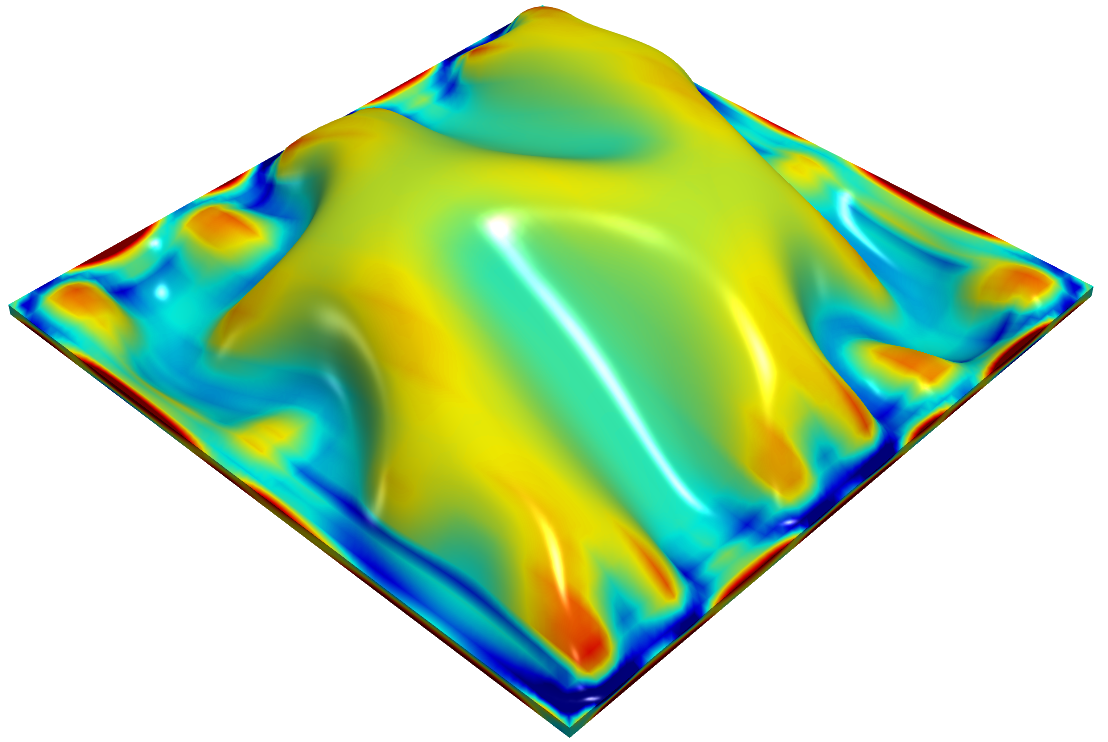
The outline of this paper is as follows. Section 2 describes the necessary elements of nonlinear continuum reversible electro-mechanics and some key variational principles. Section 3 focusses on the concept of polyconvexity as a basis for the description of phenomenological constitutive models for EAPs. The section starts with some generalised convexity conditions, before introducing the actual definition of polyconvexity or 𝒜𝒜\mathcal{A}-polyconvexity (as referred to by Šilhavý [86], also referred as Multi-Variable Convexity by Gil and Ortigosa [40]). The section summarises and puts into context key results in terms of existence of minimisers [85] and material stability for coupled reversible electro-mechanics. Section 4 describes the basis for the anisotropic invariant-based constitutive models adopted in this work, where special attention is paid to the important crystallographic groups 𝒟hsubscript𝒟\mathcal{D}_{\infty h} and 𝒞subscript𝒞\mathcal{C}_{\infty}. The section concludes by listing so-called polyconvex basis of invariants for the creation of polyconvex invariant-based constitutive models. Section 5 presents a series of numerical examples in order to assess the capabilities of the proposed model. Specifically, in a first example, a local analysis is conducted at a quadrature (Gauss point) level where the effect of orientation of anisotropy upon purely mechanical and electro-mechanical tests is presented. In the second example, complex three-dimensional bending/torsion/stretching combined modes of deformation are studied for a soft robot actuator, monitoring macroscopic stability, and observing the effect that anisotropy has in the predominance of a deformation mode against others. This will be observed only when the material is subjected to extreme deformation as it is the case of the three-dimensional bending of a multi-layered EAP. Finally, in the third example, the effect of anisotropy orientation on the wrinkling patterns is studied. Eventually, section 6 provides some concluding remarks about the paper.

2 Nonlinear continuum electromechanics

This section briefly summarises the fundamental electro-mechanical equations governing the response of an Electro-Active Polymer (EAP) at large strains.

2.1 Kinematics: motion and deformation

Let us consider the deformation of an Electro-Active Polymer (EAP) (see Figure 1) with reference configuration given by a bounded Lipschitz domain Ω03subscriptΩ0superscript3\Omega_{0}\subset\mathbb{R}^{3} with boundary Ω0subscriptΩ0\partial\Omega_{0}, and its unit outward normal 𝑵𝑵\boldsymbol{N}. After the deformation, the EAP occupies an actual configuration given by a set Ω3Ωsuperscript3\Omega\subset\mathbb{R}^{3} with boundary ΩΩ\partial\Omega and unit outward normal 𝒏𝒏\boldsymbol{n}. If the deformation is continuous and bijective then ΩΩ\Omega is also open. The deformation of the EAP is defined by a mapping ϕ:Ω03:bold-italic-ϕsubscriptΩ0superscript3\boldsymbol{\phi}:\Omega_{0}\to\mathbb{R}^{3} linking material particles 𝑿Ω0𝑿subscriptΩ0\boldsymbol{X}\in\Omega_{0} to 𝒙Ω=ϕ(Ω0)𝒙Ωbold-italic-ϕsubscriptΩ0\boldsymbol{x}\in\Omega=\boldsymbol{\phi}(\Omega_{0}). Associated with ϕ(𝑿)bold-italic-ϕ𝑿\boldsymbol{\phi}\left(\boldsymbol{X}\right), the deformation gradient tensor 𝑭𝑭\boldsymbol{F} is defined as888Lower case indices {i,j,k}𝑖𝑗𝑘\{i,j,k\} will be used to represent the spatial configuration, whereas capital case indices {I,J,K}𝐼𝐽𝐾\{I,J,K\} will be used to represent the material description. Zero as the lower index next to the nabla operator indicates that it is the referential gradient.

𝑭=0ϕ(𝑿);FiI=ϕiXI.formulae-sequence𝑭subscriptbold-∇0bold-italic-ϕ𝑿subscript𝐹𝑖𝐼subscriptitalic-ϕ𝑖subscript𝑋𝐼\boldsymbol{F}=\boldsymbol{\nabla}_{0}\boldsymbol{\phi}\left(\boldsymbol{X}\right);\qquad F_{iI}=\frac{\partial\phi_{i}}{\partial X_{I}}. (2.1)

Related to 𝑭𝑭\boldsymbol{F}, its co-factor 𝑯𝑯\boldsymbol{H} and its Jacobian J𝐽J [25, 16] are defined as

𝑯=Cof𝑭=12𝑭𝑭;J=det𝑭=13𝑯:𝑭,\displaystyle\boldsymbol{H}={\rm Cof}\,\boldsymbol{F}=\frac{1}{2}\boldsymbol{F}\mathbin{\leavevmode\hbox to5.9pt{\vbox to5.9pt{\pgfpicture\makeatletter\hbox{\hskip-0.0646pt\lower 0.0646pt\hbox to0.0pt{\pgfsys@beginscope\pgfsys@invoke{ }\definecolor{pgfstrokecolor}{rgb}{0,0,0}\pgfsys@color@rgb@stroke{0}{0}{0}\pgfsys@invoke{ }\pgfsys@color@rgb@fill{0}{0}{0}\pgfsys@invoke{ }\pgfsys@setlinewidth{0.4pt}\pgfsys@invoke{ }\nullfont\hbox to0.0pt{\pgfsys@beginscope\pgfsys@invoke{ }{}{}\pgfsys@setlinewidth{1.07639pt}\pgfsys@invoke{ }{}{{}}{} {}{}{}{{}}{} {}{}{}\pgfsys@moveto{0.6028pt}{0.6028pt}\pgfsys@lineto{5.42494pt}{5.42494pt}\pgfsys@moveto{0.6028pt}{5.42494pt}\pgfsys@lineto{5.42494pt}{0.6028pt}\pgfsys@stroke\pgfsys@invoke{ } \pgfsys@invoke{\lxSVG@closescope }\pgfsys@endscope{}{}{}\hss}\pgfsys@discardpath\pgfsys@invoke{\lxSVG@closescope }\pgfsys@endscope\hss}}\lxSVG@closescope\endpgfpicture}}}\boldsymbol{F};\qquad J={\rm det}\,\boldsymbol{F}=\frac{1}{3}\boldsymbol{H}:\boldsymbol{F}, (2.2)

with (𝑨𝑩)iI=ijkIJKAjJBkKsubscript𝑨𝑩𝑖𝐼subscript𝑖𝑗𝑘subscript𝐼𝐽𝐾subscript𝐴𝑗𝐽subscript𝐵𝑘𝐾\left(\boldsymbol{A}\mathbin{\leavevmode\hbox to5.9pt{\vbox to5.9pt{\pgfpicture\makeatletter\hbox{\hskip-0.0646pt\lower 0.0646pt\hbox to0.0pt{\pgfsys@beginscope\pgfsys@invoke{ }\definecolor{pgfstrokecolor}{rgb}{0,0,0}\pgfsys@color@rgb@stroke{0}{0}{0}\pgfsys@invoke{ }\pgfsys@color@rgb@fill{0}{0}{0}\pgfsys@invoke{ }\pgfsys@setlinewidth{0.4pt}\pgfsys@invoke{ }\nullfont\hbox to0.0pt{\pgfsys@beginscope\pgfsys@invoke{ }{}{}\pgfsys@setlinewidth{1.07639pt}\pgfsys@invoke{ }{}{{}}{} {}{}{}{{}}{} {}{}{}\pgfsys@moveto{0.6028pt}{0.6028pt}\pgfsys@lineto{5.42494pt}{5.42494pt}\pgfsys@moveto{0.6028pt}{5.42494pt}\pgfsys@lineto{5.42494pt}{0.6028pt}\pgfsys@stroke\pgfsys@invoke{ } \pgfsys@invoke{\lxSVG@closescope }\pgfsys@endscope{}{}{}\hss}\pgfsys@discardpath\pgfsys@invoke{\lxSVG@closescope }\pgfsys@endscope\hss}}\lxSVG@closescope\endpgfpicture}}}\boldsymbol{B}\right)_{iI}=\mathcal{E}_{ijk}\mathcal{E}_{IJK}A_{jJ}B_{kK}, 𝑨,𝑩3×3for-all𝑨𝑩superscript33\forall\boldsymbol{A},\boldsymbol{B}\in\mathbb{R}^{3\times 3}, where ijksubscript𝑖𝑗𝑘\mathcal{E}_{ijk} (or IJKsubscript𝐼𝐽𝐾\mathcal{E}_{IJK}) symbolises the third-order alternating tensor components and the use of repeated indices implies summation999In addition, throughout the paper, the symbol ()(\cdot) indicates the scalar product or contraction of a single index 𝒂𝒃=aibi𝒂𝒃subscript𝑎𝑖subscript𝑏𝑖\boldsymbol{a}\cdot\boldsymbol{b}=a_{i}b_{i}; the symbol (:):(:), double contraction of two indices 𝑨:𝑩=AijBij:𝑨𝑩subscript𝐴𝑖𝑗subscript𝐵𝑖𝑗\boldsymbol{A}:\boldsymbol{B}=A_{ij}B_{ij}; the symbol (×)(\times), the cross product between vectors (𝒂×𝒃)i=ijkajbksubscript𝒂𝒃𝑖subscript𝑖𝑗𝑘subscript𝑎𝑗subscript𝑏𝑘(\boldsymbol{a}\times\boldsymbol{b})_{i}=\mathcal{E}_{ijk}a_{j}b_{k}; and the symbol ()tensor-product(\otimes), the outer or dyadic product (𝒂𝒃)ij=aibjsubscripttensor-product𝒂𝒃𝑖𝑗subscript𝑎𝑖subscript𝑏𝑗(\boldsymbol{a}\otimes\boldsymbol{b})_{ij}=a_{i}b_{j}.. The deformation mapping is assumed to be sufficiently smooth, bijective and orientation preserving, so that J>0a.e.formulae-sequence𝐽0𝑎𝑒J>0\;a.e. to avoid interpenetrability.

Refer to caption
Figure 1: Deformation mapping ϕ(𝑿)bold-italic-ϕ𝑿\boldsymbol{\phi}\left(\boldsymbol{X}\right).

2.2 Governing equations in electro-mechanics

In the absence of inertial effects, the conservation of linear momentum (i.e. equilibrium) can be written in a Total Lagrangian fashion as

DIV𝑷+𝒃0DIV𝑷subscript𝒃0\displaystyle{\rm DIV}\;\bm{P}+\bm{b}_{0} =\displaystyle= 0inΩ0,0insubscriptΩ0\displaystyle 0\quad\text{in}\quad{\Omega_{0}}, (2.3)

where DIVDIV{\rm DIV} denotes the divergence operator computed in the material configuration, 𝑷𝑷\bm{P} represents the first Piola-Kirchhoff stress tensor, 𝒃0subscript𝒃0\boldsymbol{b}_{0} is a body force per unit undeformed volume, and the accompanying boundary conditions are given by

𝑷𝑵𝑷𝑵\displaystyle\bm{P}\bm{N} =𝒕¯onΩ0t;absent¯𝒕onsubscriptsuperscriptΩ𝑡0\displaystyle=\bar{\bm{t}}\quad\text{on}\quad{\partial\Omega^{t}_{0}}; (2.4a)
ϕbold-italic-ϕ\displaystyle\bm{\phi} =ϕ¯onΩ0u,absent¯bold-italic-ϕonsubscriptsuperscriptΩ𝑢0\displaystyle=\bar{\bm{\phi}}\quad\text{on}\quad{\partial\Omega^{u}_{0}}, (2.4b)

where 𝒕¯¯𝒕\bar{\bm{t}} denotes the prescribed traction over part of boundary Ω0tsuperscriptsubscriptΩ0𝑡\partial\Omega_{0}^{t}, and ϕ¯¯bold-italic-ϕ\bar{\bm{\phi}} are prescribed positions over Ω0usuperscriptsubscriptΩ0𝑢\partial\Omega_{0}^{u}, where Ω0tsuperscriptsubscriptΩ0𝑡\partial\Omega_{0}^{t} and Ω0usuperscriptsubscriptΩ0𝑢\partial\Omega_{0}^{u} are two complementary subsets, that is, ΩtΩ0u=superscriptΩ𝑡subscriptsuperscriptΩ𝑢0\partial\Omega^{t}\cap\partial\Omega^{u}_{0}=\emptyset and ΩtΩu=ΩsuperscriptΩ𝑡superscriptΩ𝑢Ω\partial\Omega^{t}\cup\partial\Omega^{u}=\partial\Omega. In addition, conservation of angular momentum leads to the well-known symmetry condition 𝑷𝑭T=𝑭𝑷T𝑷superscript𝑭𝑇𝑭superscript𝑷𝑇\bm{P}\bm{F}^{T}=\bm{F}\bm{P}^{T} [17].

In the absence of magnetic and time-dependent effects, the description of the EAP response is completed with Faraday’s and Gauss’ laws. Although, in general, the presence of electric fields in the surrounding media, that is, the vacuum, must be accounted for, in the case of EAPs this can be safely neglected due to its negligible influence101010The reader is referred to [40] for the consideration of the vacuum at a continuum level and [99, 97] for its numerical implementation.. With this in mind, Faraday’s law and associated boundary conditions are expressed as

𝑬0subscript𝑬0\displaystyle\bm{E}_{0} =0φinΩ0;absentsubscript0𝜑insubscriptΩ0\displaystyle=-\nabla_{0}\varphi\quad\text{in}\quad{\Omega_{0}}; (2.5a)
φ𝜑\displaystyle{\varphi} =φ¯onΩ0φ,absent¯𝜑onsubscriptsuperscriptΩ𝜑0\displaystyle=\bar{\varphi}\;\;\;\qquad\text{on}\quad{\partial\Omega^{\varphi}_{0}}, (2.5b)

and Gauss’ law and associated boundary condition as

DIV𝑫0DIVsubscript𝑫0\displaystyle{\rm DIV}\;\bm{D}_{0} =ρ0inΩ0;absentsubscript𝜌0insubscriptΩ0\displaystyle=\rho_{0}\qquad\text{in}\quad{\Omega_{0}}; (2.6a)
𝑫0𝑵subscript𝑫0𝑵\displaystyle\bm{D}_{0}\cdot\bm{N} =ω0onΩ0ω,absentsubscript𝜔0onsubscriptsuperscriptΩ𝜔0\displaystyle=-\omega_{0}\quad\text{on}\quad{\partial\Omega^{\omega}_{0}}, (2.6b)

where 𝑬0subscript𝑬0\bm{E}_{0} and 𝑫0subscript𝑫0\bm{D}_{0} are the Lagrangian electric field and Lagrangian electric displacement, respectively, φ𝜑\varphi is the electric potential subjected to prescribed value φ¯¯𝜑\bar{\varphi} on the boundary Ω0φsubscriptsuperscriptΩ𝜑0\partial\Omega^{\varphi}_{0}, ρ0subscript𝜌0\rho_{0} is the electric density charge per unit undeformed volume and ω0subscript𝜔0\omega_{0} is the electric charge per unit undeformed area applied over part of boundary Ω0ωsuperscriptsubscriptΩ0𝜔\partial\Omega_{0}^{\omega}, such that Ω0ωΩ0φ=subscriptsuperscriptΩ𝜔0subscriptsuperscriptΩ𝜑0\partial\Omega^{\omega}_{0}\cap\partial\Omega^{\varphi}_{0}=\emptyset and Ω0ωΩ0φ=ΩsubscriptsuperscriptΩ𝜔0subscriptsuperscriptΩ𝜑0Ω\partial\Omega^{\omega}_{0}\cup\partial\Omega^{\varphi}_{0}=\partial\Omega. To close the system of governing equations (2.1) to (2.6b), constitutive equations describing the behaviour of the EAP need to be introduced, which are presented in the following section.

2.3 Constitutive equations: reversible electro-mechanics

In the present paper, we resort to reversible behaviour described by electro-hyperelasticity [31] and introduce an internal energy e𝑒e per unit volume in Ω0subscriptΩ0\Omega_{0}, typically defined in terms of the two-point deformation gradient tensor 𝑭𝑭\boldsymbol{F} and the Lagrangian electric displacement vector 𝑫0subscript𝑫0\boldsymbol{D}_{0}, that is, e=e(𝑭,𝑫0)𝑒𝑒𝑭subscript𝑫0e=e(\boldsymbol{F},\boldsymbol{D}_{0}), where e:3×3×3{+}:𝑒superscript33superscript3e:{\mathbb{R}}^{3\times 3}\times{\mathbb{R}}^{3}\to{\mathbb{R}}\cup\{+\infty\}. For simplicity, we write e=e(𝓤)𝑒𝑒𝓤e=e(\boldsymbol{\mathcal{U}}) with 𝓤=(𝑭,𝑫0)𝓤𝑭subscript𝑫0\boldsymbol{\mathcal{U}}=\left(\boldsymbol{F},\boldsymbol{D}_{0}\right).

Following standard thermodynamic arguments, that is the so-called Coleman–Noll procedure [91], the first directional derivative of the internal energy with respect to variations δ𝓤=(δ𝑭,δ𝑫0)𝛿𝓤𝛿𝑭𝛿subscript𝑫0\delta\boldsymbol{\mathcal{U}}=(\delta\boldsymbol{F},\delta\boldsymbol{D}_{0}) gives the first Piola-Kirchhoff stress tensor 𝑷𝑷\boldsymbol{P} and the electric field 𝑬0subscript𝑬0\boldsymbol{E}_{0} as work (dual) conjugates of 𝑭𝑭\boldsymbol{F} and 𝑫0subscript𝑫0\boldsymbol{D}_{0} as

De[δ𝓤]=𝓤eδ𝓤=𝑷:δ𝑭+𝑬0δ𝑫0,:𝐷𝑒delimited-[]𝛿𝓤subscript𝓤𝑒𝛿𝓤𝑷𝛿𝑭subscript𝑬0𝛿subscript𝑫0De[\delta\boldsymbol{\mathcal{U}}]=\partial_{\boldsymbol{\mathcal{U}}}e\bullet\delta\boldsymbol{\mathcal{U}}=\boldsymbol{P}:\delta\boldsymbol{F}+\boldsymbol{E}_{0}\cdot\delta\boldsymbol{D}_{0},\qquad (2.7)

with

𝑷(𝓤)=𝑭e(𝓤);𝑬0(𝓤)=𝑫0e(𝓤),formulae-sequence𝑷𝓤subscript𝑭𝑒𝓤subscript𝑬0𝓤subscriptsubscript𝑫0𝑒𝓤\boldsymbol{P}(\boldsymbol{\mathcal{U}})={\partial_{\boldsymbol{F}}e}(\boldsymbol{\mathcal{U}});\qquad\boldsymbol{E}_{0}(\boldsymbol{\mathcal{U}})={\partial_{\boldsymbol{D}_{0}}e}(\boldsymbol{\mathcal{U}}), (2.8)

where 𝑨esubscript𝑨𝑒\partial_{\boldsymbol{A}}e denotes the partial derivative of e𝑒e with respect to the field 𝑨𝑨\boldsymbol{A} and \bullet denotes a suitable inner (dual) product. Similarly, assuming sufficient smoothness of the internal energy e𝑒e, the second directional derivative of the internal energy yields the Hessian operator esubscript𝑒\mathbb{H}_{e}, that is,

D2e[δ𝓤;δ𝓤]=δ𝓤eδ𝓤.superscript𝐷2𝑒𝛿𝓤𝛿𝓤𝛿𝓤subscript𝑒𝛿𝓤D^{2}e[\delta\boldsymbol{\mathcal{U}};\delta\boldsymbol{\mathcal{U}}]=\delta\boldsymbol{\mathcal{U}}\bullet\mathbb{H}_{e}\bullet\delta\boldsymbol{\mathcal{U}}. (2.9)

For the sake of material characterisation, it is convenient to rewrite the Hessian esubscript𝑒\mathbb{H}_{e} in terms of a fourth order type of elasticity tensor 𝓒e3×3×3×3subscript𝓒𝑒superscript3333\boldsymbol{\mathcal{C}}_{e}\in\mathbb{R}^{3\times 3\times 3\times 3}, a third order type of piezoelectric tensor 𝓠3×3×3𝓠superscript333\boldsymbol{\mathcal{Q}}\in\mathbb{R}^{3\times 3\times 3} and a second-order type of dielectric tensor 𝜽3×3𝜽superscript33\boldsymbol{\theta}\in\mathbb{R}^{3\times 3} defined as

D2e[δ𝓤;δ𝓤]=[δ𝑭:δ𝑫0]e[:δ𝑭δ𝑫0];e=[𝓒e𝓠T𝓠𝜽],D^{2}e[\delta\boldsymbol{\mathcal{U}};\delta\boldsymbol{\mathcal{U}}]=\left[\delta\boldsymbol{F}:\delta\boldsymbol{D}_{0}\cdot\right]\mathbb{H}_{e}\left[\begin{matrix}:\delta\boldsymbol{F}\\ \delta\boldsymbol{D}_{0}\end{matrix}\right];\qquad\mathbb{H}_{e}=\left[\begin{matrix}\boldsymbol{\mathcal{C}}_{e}&\boldsymbol{\mathcal{Q}}^{T}\\ \boldsymbol{\mathcal{Q}}&\boldsymbol{\mathcal{\theta}}\\ \end{matrix}\right], (2.10)

where

𝓒e(𝓤)=𝑭𝑭2e(𝓤);𝓠(𝓤)=𝑫0𝑭2e(𝓤);𝜽(𝓤)=𝑫0𝑫02e(𝓤),formulae-sequencesubscript𝓒𝑒𝓤subscriptsuperscript2𝑭𝑭𝑒𝓤formulae-sequence𝓠𝓤subscriptsuperscript2subscript𝑫0𝑭𝑒𝓤𝜽𝓤subscriptsuperscript2subscript𝑫0subscript𝑫0𝑒𝓤\boldsymbol{\mathcal{C}}_{e}(\boldsymbol{\mathcal{U}})=\partial^{2}_{\boldsymbol{FF}}e(\boldsymbol{\mathcal{U}});\qquad\boldsymbol{\mathcal{Q}}(\boldsymbol{\mathcal{U}})=\partial^{2}_{\boldsymbol{D}_{0}\boldsymbol{F}}e(\boldsymbol{\mathcal{U}});\qquad\boldsymbol{\mathcal{\theta}}(\boldsymbol{\mathcal{U}})=\partial^{2}_{\boldsymbol{D}_{0}\boldsymbol{D}_{0}}e(\boldsymbol{\mathcal{U}}), (2.11)

with (𝓠T)jJI=(𝓠)IjJsubscriptsuperscript𝓠𝑇𝑗𝐽𝐼subscript𝓠𝐼𝑗𝐽\left(\boldsymbol{\mathcal{Q}}^{T}\right)_{jJI}=\left(\boldsymbol{\mathcal{Q}}\right)_{IjJ}.

2.3.1 The Helmholtz’s free energy density function

For completeness, it is possible to introduce an alternative Helmholtz’s type of energy density Ψ=Ψ(𝓦)ΨΨ𝓦\Psi=\Psi(\boldsymbol{\mathcal{W}}) with 𝓦=(𝑭,𝑬0)𝓦𝑭subscript𝑬0\boldsymbol{\mathcal{W}}=(\boldsymbol{F},\boldsymbol{E}_{0}), where Ψ:3×3×3{+}:Ψsuperscript33superscript3\Psi:{\mathbb{R}}^{3\times 3}\times{\mathbb{R}}^{3}\to{\mathbb{R}}\cup\{+\infty\}, as

Ψ(𝓦)=sup𝑫0{𝑬0𝑫0e(𝓤)},Ψ𝓦subscriptsupremumsubscript𝑫0subscript𝑬0subscript𝑫0𝑒𝓤\Psi(\boldsymbol{\mathcal{W}})=-\sup_{\boldsymbol{D}_{0}}\left\{\boldsymbol{E}_{0}\cdot\boldsymbol{D}_{0}-e\left(\boldsymbol{\mathcal{U}}\right)\right\}, (2.12)

via the use of a partial Legendre transform in (2.12)111111A sufficient condition for the existence of the Helmholt’z energy density (2.12) is the convexity of the internal energy density e𝑒e with respect to the field 𝑫0subscript𝑫0\boldsymbol{D}_{0}., where the first Piola-Kirchhoff stress tensor and the electric displacement can be alternatively defined as

𝑷(𝓦)=𝑭Ψ(𝓦)𝑫0(𝓦)=𝑬0Ψ(𝓦).formulae-sequence𝑷𝓦subscript𝑭Ψ𝓦subscript𝑫0𝓦subscriptsubscript𝑬0Ψ𝓦\boldsymbol{P}(\boldsymbol{\mathcal{W}})=\partial_{\boldsymbol{F}}\Psi(\boldsymbol{\mathcal{W}})\qquad\boldsymbol{D}_{0}(\boldsymbol{\mathcal{W}})=-\partial_{\boldsymbol{E}_{0}}\Psi(\boldsymbol{\mathcal{W}}). (2.13)

Similarly to (2.9), the second directional derivative of the Helmholtz’s free energy density gives rise to the Hessian operator ΨsubscriptΨ\mathbb{H}_{\Psi} of ΨΨ\Psi as

D2Ψ[δ𝓦;δ𝓦]=δ𝓦Ψδ𝓦,superscript𝐷2Ψ𝛿𝓦𝛿𝓦𝛿𝓦subscriptΨ𝛿𝓦D^{2}\Psi[\delta\boldsymbol{\mathcal{W}};\delta\boldsymbol{\mathcal{W}}]=\delta\boldsymbol{\mathcal{W}}\bullet\mathbb{H}_{\Psi}\bullet\delta\boldsymbol{\mathcal{W}}, (2.14)

which can be re-expressed in terms of the elasticity tensor 𝓒Ψ3×3×3×3subscript𝓒Ψsuperscript3333\boldsymbol{\mathcal{C}}_{\Psi}\in\mathbb{R}^{3\times 3\times 3\times 3}, the piezoelectric tensor 𝓟3×3×3𝓟superscript333\boldsymbol{\mathcal{P}}\in\mathbb{R}^{3\times 3\times 3} and the dielectric tensor ϵ3×3bold-italic-ϵsuperscript33\boldsymbol{\epsilon}\in\mathbb{R}^{3\times 3} defined as

D2Ψ[δ𝓦;δ𝓦]=[δ𝑭:δ𝑬0]Ψ[:δ𝑭δ𝑬0];Ψ=[𝓒Ψ𝓟T𝓟ϵ],D^{2}\Psi[\delta\boldsymbol{\mathcal{W}};\delta\boldsymbol{\mathcal{W}}]=\left[\delta\boldsymbol{F}:\delta\boldsymbol{E}_{0}\cdot\right]\mathbb{H}_{\Psi}\left[\begin{matrix}:\delta\boldsymbol{F}\\ \delta\boldsymbol{E}_{0}\end{matrix}\right];\qquad\mathbb{H}_{\Psi}=\left[\begin{matrix}\boldsymbol{\mathcal{C}}_{\Psi}&-\boldsymbol{\mathcal{P}}^{T}\\ -\boldsymbol{\mathcal{P}}&-\boldsymbol{\mathcal{\epsilon}}\\ \end{matrix}\right], (2.15)

where

𝓒Ψ(𝓦)=𝑭𝑭2Ψ(𝓦);𝓟(𝓦)=𝑬0𝑭2Ψ(𝓦);ϵ(𝓦)=𝑬0𝑬02Ψ(𝓦),formulae-sequencesubscript𝓒Ψ𝓦subscriptsuperscript2𝑭𝑭Ψ𝓦formulae-sequence𝓟𝓦subscriptsuperscript2subscript𝑬0𝑭Ψ𝓦bold-italic-ϵ𝓦subscriptsuperscript2subscript𝑬0subscript𝑬0Ψ𝓦\boldsymbol{\mathcal{C}}_{\Psi}(\boldsymbol{\mathcal{W}})=\partial^{2}_{\boldsymbol{FF}}\Psi(\boldsymbol{\mathcal{W}});\qquad\boldsymbol{\mathcal{P}}(\boldsymbol{\mathcal{W}})=-\partial^{2}_{\boldsymbol{E}_{0}\boldsymbol{F}}\Psi(\boldsymbol{\mathcal{W}});\qquad\boldsymbol{\mathcal{\epsilon}}(\boldsymbol{\mathcal{W}})=-\partial^{2}_{\boldsymbol{E}_{0}\boldsymbol{E}_{0}}\Psi(\boldsymbol{\mathcal{W}}), (2.16)

with (𝓟T)jJI=(𝓟)IjJsubscriptsuperscript𝓟𝑇𝑗𝐽𝐼subscript𝓟𝐼𝑗𝐽\left(\boldsymbol{\mathcal{P}}^{T}\right)_{jJI}=\left(\boldsymbol{\mathcal{P}}\right)_{IjJ}. It is possible [69] to relate the components of the Hessian operators of ΨΨ\Psi (2.11) and e𝑒e (2.16) as

ϵ=𝜽1;𝓟T=𝓠ϵ;𝓒Ψ=𝓒e+𝓠T𝓟,formulae-sequencebold-italic-ϵsuperscript𝜽1formulae-sequencesuperscript𝓟𝑇𝓠bold-italic-ϵsubscript𝓒Ψsubscript𝓒𝑒superscript𝓠𝑇𝓟\displaystyle\boldsymbol{\epsilon}=\boldsymbol{\theta}^{-1};\qquad\boldsymbol{\mathcal{P}}^{T}=-\boldsymbol{\mathcal{Q}}\cdot\boldsymbol{\epsilon};\qquad\boldsymbol{\mathcal{C}}_{\Psi}=\boldsymbol{\mathcal{C}}_{e}+\boldsymbol{\mathcal{Q}}^{T}\cdot\boldsymbol{\mathcal{P}}, (2.17)

where the inner product \cdot above indicates contraction of the indices placed immediately before and after it.

2.4 Variational principles in reversible electro-mechanics

The solution of the boundary value problem defined by the governing equations (2.1) to (2.6b), in conjunction with a suitable definition of the internal energy density e𝑒e or Helmholtz’s free energy density ΨΨ\Psi, is typically solved based on the direct methods of the calculus of variations. With that in mind, the first mixed variational principle can be introduced as

(ϕ,𝑫0)=arginf𝒜ΠeΠe(ϕ,𝑫0),superscriptbold-italic-ϕsuperscriptsubscript𝑫0argsubscriptinfimumsubscript𝒜subscriptΠ𝑒subscriptΠ𝑒bold-italic-ϕsubscript𝑫0(\boldsymbol{\phi}^{\ast},\boldsymbol{D}_{0}^{\ast})=\text{arg}\inf_{\mathcal{A}_{\Pi_{e}}}\Pi_{e}\left(\boldsymbol{\phi},\boldsymbol{D}_{0}\right), (2.18)

where

Πe(ϕ,𝑫0)=Ω0e(𝑭,𝑫0)𝑑VΠextm(ϕ),subscriptΠ𝑒bold-italic-ϕsubscript𝑫0subscriptsubscriptΩ0𝑒𝑭subscript𝑫0differential-d𝑉superscriptsubscriptΠext𝑚bold-italic-ϕ\Pi_{e}\left(\boldsymbol{\phi},\boldsymbol{D}_{0}\right)=\int_{{\Omega}_{0}}e\left(\boldsymbol{\boldsymbol{F}},\boldsymbol{D}_{0}\right)\,dV-\Pi_{\text{ext}}^{m}\left(\boldsymbol{\phi}\right), (2.19)

Πextm(ϕ)superscriptsubscriptΠext𝑚bold-italic-ϕ\Pi_{\text{ext}}^{m}(\boldsymbol{\phi}) representing the external work done by the mechanical actions, defined as

Πextm(ϕ)=Ω0𝒃0ϕ𝑑V+Ω0t𝒕¯ϕ𝑑A,superscriptsubscriptΠext𝑚bold-italic-ϕsubscriptsubscriptΩ0subscript𝒃0bold-italic-ϕdifferential-d𝑉subscriptsuperscriptsubscriptΩ0𝑡¯𝒕bold-italic-ϕdifferential-d𝐴\Pi_{\text{ext}}^{m}\left(\boldsymbol{\phi}\right)=\int_{\Omega_{0}}\boldsymbol{b}_{0}\cdot\boldsymbol{\phi}\,dV+\int_{\partial\Omega_{0}^{t}}\bar{\boldsymbol{t}}\cdot\boldsymbol{\phi}\,dA, (2.20)

and with the functional space 𝒜Πesubscript𝒜subscriptΠ𝑒\mathcal{A}_{\Pi_{e}} given by

𝒜Πe={ϕ𝒢ϕ(Ω0;3),𝑫0𝒢𝑫0(Ω0;3);s.t.(2.4b),(2.6a),(2.6b)}.\mathcal{A}_{\Pi_{e}}=\left\{\boldsymbol{\phi}\subset\mathcal{G}_{\boldsymbol{\phi}}(\Omega_{0};{\mathbb{R}}^{3}),\boldsymbol{D}_{0}\subset\mathcal{G}_{\boldsymbol{D}_{0}}(\Omega_{0};{\mathbb{R}}^{3});\;\text{s.t}.\eqref{eqn:Dirich_displacements},\eqref{eq:DivD_a},\eqref{eq:DivD_b}\right\}. (2.21)

with 𝒢ϕ,𝒢𝑫0subscript𝒢bold-italic-ϕsubscript𝒢subscript𝑫0\mathcal{G}_{\boldsymbol{\phi}},\mathcal{G}_{\boldsymbol{D}_{0}} suitable functional spaces to be defined. The use of the asterisk ()superscript(\cdot)^{\ast} in (2.18) denotes the solution (minimiser) of the variational principle. As it is well-known, for the existence of minimisers of the above variational problem, some mathematical restrictions must be imposed on 1) 𝒜Πesubscript𝒜subscriptΠ𝑒\mathcal{A}_{\Pi_{e}} and 2) the form that the internal energy density e𝑒e must adopt [7, 86], which will be the focus of the following section.

From the computational standpoint, it is convenient to resort to an alternative variational principle in order to by-pass the strong imposition of conditions (2.6) and allow the possibility of imposing boundary conditions directly on the electric potential (i.e. via electrodes attached to the EAP). Indeed, after the introduction of the electric potential φ𝜑\varphi (which can be understood as a Lagrange multiplier for the weak enforcement of Gauss’ law (2.6)), the second mixed variational principle emerges as

(ϕ,φ,𝑫0)=arginf𝒜Π~e,ϕinf𝒜Π~e,𝑫0sup𝒜Π~e,φΠ~e(ϕ,φ,𝑫0),superscriptbold-italic-ϕsuperscript𝜑superscriptsubscript𝑫0argsubscriptinfimumsubscript𝒜subscript~Π𝑒bold-italic-ϕsubscriptinfimumsubscript𝒜subscript~Π𝑒subscript𝑫0subscriptsupremumsubscript𝒜subscript~Π𝑒𝜑subscript~Π𝑒bold-italic-ϕ𝜑subscript𝑫0(\boldsymbol{\phi}^{\ast},\varphi^{\ast},\boldsymbol{D}_{0}^{\ast})=\text{arg}\inf_{\mathcal{A}_{\tilde{\Pi}_{e,\boldsymbol{\phi}}}}\inf_{\mathcal{A}_{\tilde{\Pi}_{e,\boldsymbol{D}_{0}}}}\sup_{\mathcal{A}_{\tilde{\Pi}_{e,\varphi}}}\tilde{\Pi}_{e}\left(\boldsymbol{\phi},\varphi,\boldsymbol{D}_{0}\right), (2.22)

where

Π~e(ϕ,φ,𝑫0)=Ω0e(𝑭,𝑫0)𝑑V+Ω0𝑫00φdVΠext(ϕ,φ),subscript~Π𝑒bold-italic-ϕ𝜑subscript𝑫0subscriptsubscriptΩ0𝑒𝑭subscript𝑫0differential-d𝑉subscriptsubscriptΩ0subscript𝑫0subscriptbold-∇0𝜑𝑑𝑉subscriptΠextbold-italic-ϕ𝜑\tilde{\Pi}_{e}\left(\boldsymbol{\phi},\varphi,\boldsymbol{D}_{0}\right)=\int_{{\Omega}_{0}}e\left(\boldsymbol{F},\boldsymbol{D}_{0}\right)\,dV+\int_{{\Omega}_{0}}\boldsymbol{D}_{0}\cdot\boldsymbol{\nabla}_{0}\varphi\,dV-\Pi_{\text{ext}}\left(\boldsymbol{\phi},\varphi\right), (2.23)

where Πext(ϕ,φ)subscriptΠextbold-italic-ϕ𝜑\Pi_{\text{ext}}(\boldsymbol{\phi},\varphi) represents the combined external work done by the mechanical and electrical actions, defined as

Πext(ϕ,φ)=Πextm(ϕ)+Πexte(φ);Πexte(φ)=Ω0ρ0φ𝑑VΩ0tω0φ𝑑A,formulae-sequencesubscriptΠextbold-italic-ϕ𝜑superscriptsubscriptΠext𝑚bold-italic-ϕsuperscriptsubscriptΠext𝑒𝜑superscriptsubscriptΠext𝑒𝜑subscriptsubscriptΩ0subscript𝜌0𝜑differential-d𝑉subscriptsuperscriptsubscriptΩ0𝑡subscript𝜔0𝜑differential-d𝐴\Pi_{\text{ext}}\left(\boldsymbol{\phi},\varphi\right)=\Pi_{\text{ext}}^{m}\left(\boldsymbol{\phi}\right)+\Pi_{\text{ext}}^{e}\left({\varphi}\right);\qquad\Pi_{\text{ext}}^{e}\left({\varphi}\right)=-\int_{\Omega_{0}}\rho_{0}{\varphi}\,dV-\int_{\partial\Omega_{0}^{t}}\omega_{0}{\varphi}\,dA, (2.24)

and with

𝒜Π~e,ϕsubscript𝒜subscript~Π𝑒bold-italic-ϕ\displaystyle\mathcal{A}_{\tilde{\Pi}_{e,\boldsymbol{\phi}}} ={ϕ𝒢~ϕ(Ω0;3);s.t.(2.4b)};\displaystyle=\left\{\boldsymbol{\phi}\subset\tilde{\mathcal{G}}_{\boldsymbol{\phi}}(\Omega_{0};{\mathbb{R}}^{3});\;\text{s.t}.\eqref{eqn:Dirich_displacements}\right\};\; (2.25)
𝒜Π~e,𝑫0subscript𝒜subscript~Π𝑒subscript𝑫0\displaystyle\mathcal{A}_{\tilde{\Pi}_{e,\boldsymbol{D}_{0}}} ={𝑫0𝒢~𝑫0(Ω0;3)};absentsubscript𝑫0subscript~𝒢subscript𝑫0subscriptΩ0superscript3\displaystyle=\left\{\boldsymbol{D}_{0}\subset\tilde{\mathcal{G}}_{\boldsymbol{D}_{0}}(\Omega_{0};{\mathbb{R}}^{3})\right\};\;
𝒜Π~e,φsubscript𝒜subscript~Π𝑒𝜑\displaystyle\mathcal{A}_{\tilde{\Pi}_{e,\varphi}} ={φ𝒢~φ(Ω0;);s.t.(2.5b)},\displaystyle=\left\{\varphi\subset\tilde{\mathcal{G}}_{\varphi}(\Omega_{0};{\mathbb{R}});\;\text{s.t}.\eqref{eqn:Dirichlet_potential}\right\},

with 𝒢~ϕ,𝒢~𝑫0,𝒢~φsubscript~𝒢bold-italic-ϕsubscript~𝒢subscript𝑫0subscript~𝒢𝜑\tilde{\mathcal{G}}_{\boldsymbol{\phi}},\tilde{\mathcal{G}}_{\boldsymbol{D}_{0}},\tilde{\mathcal{G}}_{\varphi} suitable functional spaces to be defined. This variational principle (2.22) will be the one selected for the numerical examples presented later on in this paper, due to its excellent accuracy as a result of its extended nature.

Furthermore, use of the Helmholtz’s free energy density functional (2.12) in (2.22) leads to the third mixed variational principle as follows,

(ϕ,φ)=arginf𝒜Ψϕsup𝒜ΨφΠΨ(ϕ,φ),superscriptbold-italic-ϕsuperscript𝜑argsubscriptinfimumsubscript𝒜subscriptΨbold-italic-ϕsubscriptsupremumsubscript𝒜subscriptΨ𝜑subscriptΠΨbold-italic-ϕ𝜑(\boldsymbol{\phi}^{\ast},\varphi^{\ast})=\text{arg}\inf_{\mathcal{A}_{\Psi_{\boldsymbol{\phi}}}}\sup_{\mathcal{A}_{\Psi_{\varphi}}}\Pi_{\Psi}\left(\boldsymbol{\phi},\varphi\right), (2.26)

where

ΠΨ(ϕ,φ)=Ω0Ψ(𝑭,𝑬0)𝑑VΠext(ϕ,φ),subscriptΠΨbold-italic-ϕ𝜑subscriptsubscriptΩ0Ψ𝑭subscript𝑬0differential-d𝑉subscriptΠextbold-italic-ϕ𝜑\Pi_{\Psi}\left(\boldsymbol{\phi},\varphi\right)=\int_{{\Omega}_{0}}\Psi\left(\boldsymbol{F},\boldsymbol{E}_{0}\right)\,dV-\Pi_{\text{ext}}\left(\boldsymbol{\phi},\varphi\right), (2.27)

where 𝒜Ψϕsubscript𝒜subscriptΨbold-italic-ϕ\mathcal{A}_{\Psi_{\boldsymbol{\phi}}} and 𝒜Ψφsubscript𝒜subscriptΨ𝜑\mathcal{A}_{\Psi_{\varphi}} are suitably adapted functional spaces analogous to their counterparts 𝒜Π~e,ϕsubscript𝒜subscript~Π𝑒bold-italic-ϕ\mathcal{A}_{\tilde{\Pi}_{e,\boldsymbol{\phi}}} and 𝒜Π~e,φsubscript𝒜subscript~Π𝑒𝜑\mathcal{A}_{\tilde{\Pi}_{e,\varphi}} in (2.25). The latter variational principle is typically preferred for numerical simulations due to its compact form and reduced number of degrees of freedom, described solely in terms of the mapping ϕsuperscriptitalic-ϕ\phi^{\ast} and the electrical potential φsuperscript𝜑\varphi^{\ast}.

3 Polyconvexity in electromechanics

To ensure the existence of solutions of the above variational principles ΠesubscriptΠ𝑒\Pi_{e} (2.18), Π~esubscript~Π𝑒\tilde{\Pi}_{e} (2.22) or ΠΨsubscriptΠΨ\Pi_{\Psi} (2.26), the energy density e𝑒e must fulfil certain mathematical requirements. In particular, we require, that the energy functionals are lower semicontinuous in a suitable topology. This relates to the convexity properties of the integrands. Prior to introducing the notion of polyconvexity in the context of electromechanics, the section starts by introducing some alternative mathematical restrictions (the reader is referred to the monograph [84] for an in-depth discussion in the context of mechanics). The section continues by introducing the requirement of polyconvexity and its most relevant implications, namely, the existence of minimisers and the assurance of material stability.

3.1 Some notions on generalised convexity conditions

One of the simplest conditions is that of convexity of e(𝓤)𝑒𝓤e(\boldsymbol{\mathcal{U}}), that is

e(λ𝓤1+(1λ)𝓤2)λe(𝓤1)+(1λ)e(𝓤2);𝓤1,𝓤2;λ[0,1],formulae-sequence𝑒𝜆subscript𝓤11𝜆subscript𝓤2𝜆𝑒subscript𝓤11𝜆𝑒subscript𝓤2for-allsubscript𝓤1subscript𝓤2𝜆01e(\lambda\boldsymbol{\mathcal{U}}_{1}+(1-\lambda)\boldsymbol{\mathcal{U}}_{2})\leq\lambda e(\boldsymbol{\mathcal{U}}_{1})+(1-\lambda)e(\boldsymbol{\mathcal{U}}_{2});\quad\forall\;\boldsymbol{\mathcal{U}}_{1},\boldsymbol{\mathcal{U}}_{2};\quad\lambda\in[0,1], (3.1)

which for functions with first order differentiability can be alternatively written as

e(𝓤+δ𝓤)e(𝓤)De(𝓤)[δ𝓤]0;𝓤,δ𝓤,𝑒𝓤𝛿𝓤𝑒𝓤𝐷𝑒𝓤delimited-[]𝛿𝓤0for-all𝓤𝛿𝓤e(\boldsymbol{\mathcal{U}}+\delta\boldsymbol{\mathcal{U}})-e(\boldsymbol{\mathcal{U}})-De(\boldsymbol{\mathcal{U}})[\delta\boldsymbol{\mathcal{U}}]\geq 0;\qquad\forall\,\boldsymbol{\mathcal{U}},\delta\boldsymbol{\mathcal{U}}, (3.2)

and for functions with second order differentiability (in terms of the Hessian [e]delimited-[]subscript𝑒[\mathbb{H}_{e}]) as

D2e(𝓤)[δ𝓤;δ𝓤]=δ𝓤[e]δ𝓤0;𝓤,δ𝓤,formulae-sequencesuperscript𝐷2𝑒𝓤𝛿𝓤𝛿𝓤𝛿𝓤delimited-[]subscript𝑒𝛿𝓤0for-all𝓤𝛿𝓤D^{2}e(\boldsymbol{\mathcal{U}})[\delta\boldsymbol{\mathcal{U}};\delta\boldsymbol{\mathcal{U}}]=\delta\boldsymbol{\mathcal{U}}\bullet[\mathbb{H}_{e}]\bullet\delta\boldsymbol{\mathcal{U}}\geq 0;\qquad\forall\,\boldsymbol{\mathcal{U}},\delta\boldsymbol{\mathcal{U}}, (3.3)

which requires (refer to (2.10), (2.11)) positive semi-definiteness of 𝓒esubscript𝓒𝑒\boldsymbol{\mathcal{C}}_{e} and 𝜽𝜽\boldsymbol{\theta}, independently, and further restrictions on the form that the third-order tensor 𝓠𝓠\boldsymbol{\mathcal{Q}} can adopt. However, convexity away from the origin (i.e. 𝑭𝑰𝑭𝑰\boldsymbol{F}\approx\boldsymbol{I} and 𝑫0𝟎subscript𝑫00\boldsymbol{D}_{0}\approx\boldsymbol{0}) is not a suitable physical restriction as it precludes the realistic behavior of materials such as buckling in the purely mechanical context, as well as the possibility of voltage-induced buckling, inherent to soft dielectric materials [33]. An alternative mathematical restriction is that of 𝒜𝒜\mathcal{A}-quasiconvexity of e𝑒e [34]. Unfortunately, 𝒜𝒜\mathcal{A}-quasiconvexity is a nonlocal condition that is very difficult even impossible to be verified.

A necessary restriction implied by 𝒜𝒜\mathcal{A}-quasiconvexity is that of generalised rank-one convexity of e𝑒e. A generalised rank-one convex energy density verifies

e(λ𝓤+(1λ)𝓤~)λe(𝓤)+(1λ)e(𝓤~);𝓤;λ[0,1],formulae-sequence𝑒𝜆𝓤1𝜆~𝓤𝜆𝑒𝓤1𝜆𝑒~𝓤for-all𝓤𝜆01e(\lambda\boldsymbol{\mathcal{U}}+(1-\lambda)\tilde{\boldsymbol{\mathcal{U}}})\leq\lambda e(\boldsymbol{\mathcal{U}})+(1-\lambda)e(\tilde{\boldsymbol{\mathcal{U}}});\quad\forall\;\boldsymbol{\mathcal{U}};\quad\lambda\in[0,1], (3.4)

and with 𝓤~=𝓤+δ𝓤~𝓤𝓤𝛿𝓤\tilde{\boldsymbol{\mathcal{U}}}=\boldsymbol{\mathcal{U}}+\delta\boldsymbol{\mathcal{U}} and δ𝓤=(𝒖𝑽,𝑽)𝛿𝓤tensor-product𝒖𝑽subscript𝑽perpendicular-to\delta\boldsymbol{\mathcal{U}}=(\boldsymbol{u}\otimes\boldsymbol{V},\boldsymbol{V}_{\perp}), where 𝑽𝑽=0𝑽subscript𝑽perpendicular-to0\boldsymbol{V}\cdot\boldsymbol{V_{\perp}}=0 and with 𝒖𝒖\boldsymbol{u}, 𝑽𝑽\boldsymbol{V} and 𝑽subscript𝑽perpendicular-to\boldsymbol{V}_{\perp} any arbitrary vectors. For the case of energies with first order differentiability, generalised rank-one convexity can alternatively be written as

e(𝓤+δ𝓤)e(𝓤)De(𝓤)[δ𝓤]0;δ𝓤=(𝒖𝑽,𝑽);𝓤,𝒖,𝑽,𝑽,formulae-sequence𝑒𝓤𝛿𝓤𝑒𝓤𝐷𝑒𝓤delimited-[]𝛿𝓤0𝛿𝓤tensor-product𝒖𝑽subscript𝑽perpendicular-tofor-all𝓤𝒖𝑽subscript𝑽perpendicular-toe(\boldsymbol{\mathcal{U}}+\delta\boldsymbol{\mathcal{U}})-e(\boldsymbol{\mathcal{U}})-De(\boldsymbol{\mathcal{U}})[\delta\boldsymbol{\mathcal{U}}]\geq 0;\qquad\delta\boldsymbol{\mathcal{U}}=(\boldsymbol{u}\otimes\boldsymbol{V},\boldsymbol{V}_{\perp});\qquad\forall\,\boldsymbol{\mathcal{U}},\boldsymbol{u},\boldsymbol{V},\boldsymbol{V}_{\perp}, (3.5)

and for energies with second order differentiability,

D2e(𝓤)[δ𝓤;δ𝓤]=δ𝓤eδ𝓤0;δ𝓤=(𝒖𝑽,𝑽);𝓤,𝒖,𝑽,𝑽.formulae-sequencesuperscript𝐷2𝑒𝓤𝛿𝓤𝛿𝓤𝛿𝓤subscript𝑒𝛿𝓤0𝛿𝓤tensor-product𝒖𝑽subscript𝑽perpendicular-tofor-all𝓤𝒖𝑽subscript𝑽perpendicular-toD^{2}e(\boldsymbol{\mathcal{U}})[\delta\boldsymbol{\mathcal{U}};\delta\boldsymbol{\mathcal{U}}]=\delta\boldsymbol{\mathcal{U}}\bullet\mathbb{H}_{e}\bullet\delta\boldsymbol{\mathcal{U}}\geq 0;\qquad\delta\boldsymbol{\mathcal{U}}=(\boldsymbol{u}\otimes\boldsymbol{V},\boldsymbol{V}_{\perp});\qquad\forall\,\boldsymbol{\mathcal{U}},\boldsymbol{u},\boldsymbol{V},\boldsymbol{V}_{\perp}. (3.6)

The generalised rank-one convexity restriction in its form (3.5) plays a key role in the suitable definition of jump conditions across a travelling interface defined by a normal vector 𝑽𝑽\boldsymbol{V} moving with speed c𝑐c (i.e. singular surface [83]). Analogously, condition (3.6) is referred to as the Legendre-Hadamard condition or ellipticity of e𝑒e, linked to the propagation of travelling plane wave within the material defined by a vector 𝑽𝑽\boldsymbol{V} and speed c𝑐c. These two aspects will be presented in the following two subsections.

3.1.1 Generalised rank-one convexity conditions and jump conditions

Consider a travelling discontinuity within an EAP, moving at speed c𝑐c and defined by a normal vector 𝑽𝑽\boldsymbol{V} separating states ()asuperscript𝑎(\bullet)^{a} and ()bsuperscript𝑏(\bullet)^{b}, where =()a()b\llbracket\bullet\rrbracket=(\bullet)^{a}-(\bullet)^{b} denotes the jump across the interface and ()Av=1/2(()a+()b)superscriptAv12superscript𝑎superscript𝑏(\bullet)^{{\text{Av}}}=1/2((\bullet)^{a}+(\bullet)^{b}) the average state. Following [66], the jump or Rankine-Hugoniot conditions for the combined set of Cauchy-Maxwell (electro-magneto-mechanical) equations are given by

c𝑭\displaystyle-c\llbracket\boldsymbol{F}\rrbracket =𝒗𝑽;\displaystyle=\llbracket\boldsymbol{v}\rrbracket\otimes\boldsymbol{V}; (3.7a)
cρR𝒗\displaystyle-c\rho_{R}\llbracket\boldsymbol{v}\rrbracket =𝑷𝑽;\displaystyle=\llbracket\boldsymbol{P}\rrbracket\boldsymbol{V}; (3.7b)
c𝑩0\displaystyle-c\llbracket\boldsymbol{B}_{0}\rrbracket =𝑬0×𝑽;\displaystyle=\llbracket\boldsymbol{E}_{0}\rrbracket\times\boldsymbol{V}; (3.7c)
c𝑫0\displaystyle c\llbracket\boldsymbol{D}_{0}\rrbracket =𝑯0×𝑽;\displaystyle=\llbracket\boldsymbol{H}_{0}\rrbracket\times\boldsymbol{V}; (3.7d)
ce+1/2ρR𝒗𝒗\displaystyle-c\llbracket e+1/2\rho_{R}\boldsymbol{v}\cdot\boldsymbol{v}\rrbracket =𝒗𝑷𝑽𝑬0×𝑯0𝑽,\displaystyle=\llbracket\boldsymbol{v}\cdot\boldsymbol{P}\rrbracket\cdot\boldsymbol{V}-\llbracket\boldsymbol{E}_{0}\times\boldsymbol{H}_{0}\rrbracket\cdot\boldsymbol{V}, (3.7e)

where, in addition to previously defined fields, ρRsubscript𝜌𝑅\rho_{R}, 𝒗𝒗\boldsymbol{v}, 𝑩0subscript𝑩0\boldsymbol{B}_{0} and 𝑯0subscript𝑯0\boldsymbol{H}_{0} denote the density of the material per unit undeformed volume, the velocity, the magnetic induction vector and the magnetic field, respectively. Substitution of (3.7a)-(3.7d) into (3.7e) renders

edelimited-⟦⟧𝑒\displaystyle\llbracket e\rrbracket =𝑷Av:𝑭+𝑬0Av𝑫0+𝑯0Av𝑩0,\displaystyle=\boldsymbol{P}^{\text{Av}}:\llbracket\boldsymbol{F}\rrbracket+\boldsymbol{E}_{0}^{\text{Av}}\cdot\llbracket\boldsymbol{D}_{0}\rrbracket+\boldsymbol{H}_{0}^{\text{Av}}\cdot\llbracket\boldsymbol{B}_{0}\rrbracket, (3.8)

which, by re-defining ()Av=()a+/2(\bullet)^{\text{Av}}=(\bullet)^{a}+\llbracket\bullet\rrbracket/2 and removing the upper index ()asuperscript𝑎(\bullet)^{a} for simplicity, can be rewritten as

e𝑷:𝑭𝑬0𝑫0𝑯0𝑩0\displaystyle\llbracket e\rrbracket-\boldsymbol{P}:\llbracket\boldsymbol{F}\rrbracket-\boldsymbol{E}_{0}\cdot\llbracket\boldsymbol{D}_{0}\rrbracket-\boldsymbol{H}_{0}\cdot\llbracket\boldsymbol{B}_{0}\rrbracket =𝑷:𝑭+𝑬0𝑫0+𝑯0𝑩0.\displaystyle=\llbracket\boldsymbol{P}\rrbracket:\llbracket\boldsymbol{F}\rrbracket+\llbracket\boldsymbol{E}_{0}\rrbracket\cdot\llbracket\boldsymbol{D}_{0}\rrbracket+\llbracket\boldsymbol{H}_{0}\rrbracket\cdot\llbracket\boldsymbol{B}_{0}\rrbracket. (3.9)

For the case when magnetic effects are neglected (i.e. 𝑩0𝟎\llbracket\boldsymbol{B}_{0}\rrbracket\approx\boldsymbol{0}) the last term on both sides of above equation (3.9) can be neglected. Moreover, notice that the term 𝑬0𝑫0𝟎\llbracket\boldsymbol{E}_{0}\rrbracket\cdot\llbracket\boldsymbol{D}_{0}\rrbracket\approx\boldsymbol{0} as 𝑬0subscript𝑬0\boldsymbol{E}_{0} can only jump tangentially across the discontinuity (refer to (3.7c)) whilst 𝑫0subscript𝑫0\boldsymbol{D}_{0} can only jump along 𝑽𝑽\boldsymbol{V} (refer to (3.7d)), that is, 𝑫0=𝑽\llbracket\boldsymbol{D}_{0}\rrbracket=\boldsymbol{V}_{\perp}, 𝑽𝑽=0𝑽subscript𝑽perpendicular-to0\boldsymbol{V}\cdot\boldsymbol{V}_{\perp}=0. Thus, we arrive at the simpler equation

e𝑷:𝑭𝑬0𝑽\displaystyle\llbracket e\rrbracket-\boldsymbol{P}:\llbracket\boldsymbol{F}\rrbracket-\boldsymbol{E}_{0}\cdot\boldsymbol{V}_{\perp} =𝑷:𝑭.\displaystyle=\llbracket\boldsymbol{P}\rrbracket:\llbracket\boldsymbol{F}\rrbracket. (3.10)

Redefining 𝒗/c=𝒖-\llbracket\boldsymbol{v}\rrbracket/c=\boldsymbol{u}, that is 𝑭=𝒖𝑽\llbracket\boldsymbol{F}\rrbracket=\boldsymbol{u}\otimes\boldsymbol{V}, and making use of (3.7a) and (3.7b), it is straightforward to show that 𝑷:𝑭=ρRc2𝒖𝒖\llbracket\boldsymbol{P}\rrbracket:\llbracket\boldsymbol{F}\rrbracket=\rho_{R}c^{2}\boldsymbol{u}\cdot\boldsymbol{u}, which finally gives

e𝑷:(𝒖𝑽)𝑬0𝑽\displaystyle\llbracket e\rrbracket-\boldsymbol{P}:(\boldsymbol{u}\otimes\boldsymbol{V})-\boldsymbol{E}_{0}\cdot\boldsymbol{V}_{\perp} =ρRc2𝒖𝒖0,absentsubscript𝜌𝑅superscript𝑐2𝒖𝒖0\displaystyle=\rho_{R}c^{2}\boldsymbol{u}\cdot\boldsymbol{u}\geq 0, (3.11)

which can be equivalently written as

e(𝑭+𝒖𝑽,𝑫0+𝑽)e(𝑭,𝑫0)𝑭e(𝑭,𝑫0):(𝒖𝑽)𝑫0e(𝑭,𝑫0)𝑽0.:𝑒𝑭tensor-product𝒖𝑽subscript𝑫0subscript𝑽perpendicular-to𝑒𝑭subscript𝑫0subscript𝑭𝑒𝑭subscript𝑫0tensor-product𝒖𝑽subscriptsubscript𝑫0𝑒𝑭subscript𝑫0subscript𝑽perpendicular-to0e(\boldsymbol{F}+\boldsymbol{u}\otimes\boldsymbol{V},\boldsymbol{D}_{0}+\boldsymbol{V}_{\perp})-e(\boldsymbol{F},\boldsymbol{D}_{0})-\partial_{\boldsymbol{F}}e(\boldsymbol{F},\boldsymbol{D}_{0}):(\boldsymbol{u}\otimes\boldsymbol{V})-\partial_{\boldsymbol{D}_{0}}e(\boldsymbol{F},\boldsymbol{D}_{0})\cdot\boldsymbol{V}_{\perp}\geq 0. (3.12)

Notice that above inequality (3.12) holds for an energy density e𝑒e defined as generalised rank-one convexity (refer to equation (3.5)).

3.1.2 Ellipticity and Legendre-Hadamard condition

Condition (3.6) is referred to as the Legendre-Hadamard condition or ellipticity of e𝑒e and is related to the propagation of travelling plane waves121212This concept is also strongly related to that of the propagation of acceleration waves within a discontinuity defined by a normal vector 𝑽𝑽\boldsymbol{V} with speed c𝑐c. within the material defined by a vector 𝑽𝑽\boldsymbol{V} and speed c𝑐c. Notice that the above expression (3.6) is a generalisation of the concept of ellipticity from elasticity to the more general case of electro-elasticity, which can be easily verified by neglecting the piezoelectric and dielectric components of the Hessian operator, that is

(𝒖𝑽):𝓒e(𝓤):(𝒖𝑽)0;𝓤,𝒖,𝑽.:tensor-product𝒖𝑽subscript𝓒𝑒𝓤:matrixtensor-product𝒖𝑽0for-all𝓤𝒖𝑽\left(\boldsymbol{u}\otimes\boldsymbol{V}\right):\boldsymbol{\mathcal{C}}_{e}(\boldsymbol{\mathcal{U}}):\left(\begin{matrix}\boldsymbol{u}\otimes\boldsymbol{V}\end{matrix}\right)\geq 0;\qquad\forall\,\boldsymbol{\mathcal{U}},\boldsymbol{u},\boldsymbol{V}. (3.13)

Similarly, particularising for 𝒖=𝟎𝒖0\boldsymbol{u}=\boldsymbol{0} in either (3.5) or (3.6), it reduces to the condition of convexity with respect to 𝑫0subscript𝑫0\boldsymbol{D}_{0}. This condition is crucial in order to guarantee the existence of the Helmholtz’s free energy density function (2.12) and thus that of the variational principle ΠΨsubscriptΠΨ\Pi_{\Psi} (2.26).

The derivation of the above Legendre-Hadamard condition (3.6) has its roots in the study of the hyperbolicity (or stability in the quasi-static case) of the system of the generalised Cauchy-Maxwell equations [66] in order to ensure the existence of real wave speeds propagating throughout the domain. Crucially, the ab initio existence of real wave speeds for the specific system of governing equations (2.1) to (2.6b) (i.e. magnetic and time-dependent effects are neglected in the Maxwell equations) can be monitored via the study of the so-called electro-mechanical acoustic tensor 𝑸𝑸\boldsymbol{Q} defined as

𝑸=𝓒𝒆,𝑽𝑽+𝓠𝑽T𝜽1[𝑽𝜽1𝑽𝑽𝜽1𝑽𝑰]𝓠𝑽,𝑸subscript𝓒𝒆𝑽𝑽superscriptsubscript𝓠𝑽𝑇superscript𝜽1delimited-[]tensor-product𝑽superscript𝜽1𝑽𝑽superscript𝜽1𝑽𝑰subscript𝓠𝑽\boldsymbol{Q}=\boldsymbol{\mathcal{C}_{e,\boldsymbol{V}\boldsymbol{V}}}+\boldsymbol{\mathcal{Q}_{\boldsymbol{V}}}^{T}\boldsymbol{\mathcal{\theta}}^{-1}\left[\frac{\boldsymbol{\boldsymbol{V}}\otimes\boldsymbol{\mathcal{\theta}}^{-1}\boldsymbol{V}}{\boldsymbol{V}\cdot\boldsymbol{\mathcal{\theta}}^{-1}\boldsymbol{V}}-\boldsymbol{I}\right]\boldsymbol{\mathcal{Q}_{\boldsymbol{V}}}, (3.14)

where

[𝓒𝒆,𝑽𝑽]ij=𝒞e,iIjJVIVJ,[𝓠𝑽]Ij=𝒬IjJVJ,[𝑰]IJ=δIJ.formulae-sequencesubscriptdelimited-[]subscript𝓒𝒆𝑽𝑽𝑖𝑗subscript𝒞𝑒𝑖𝐼𝑗𝐽subscript𝑉𝐼subscript𝑉𝐽formulae-sequencesubscriptdelimited-[]subscript𝓠𝑽𝐼𝑗subscript𝒬𝐼𝑗𝐽subscript𝑉𝐽subscriptdelimited-[]𝑰𝐼𝐽subscript𝛿𝐼𝐽\left[\boldsymbol{\mathcal{C}_{e,\boldsymbol{V}\boldsymbol{V}}}\right]_{ij}=\mathcal{C}_{e,iIjJ}V_{I}V_{J},\qquad\left[\boldsymbol{\mathcal{Q}_{\boldsymbol{V}}}\right]_{Ij}=\mathcal{Q}_{IjJ}V_{J},\qquad\left[\boldsymbol{I}\right]_{IJ}=\delta_{IJ}. (3.15)

Specifically, the eigenvalues of the acoustic tensor 𝑸𝑸\boldsymbol{Q} are proportional to the squared of the volumetric and shear wave speeds of the electroactive material. Hence, the above tensor 𝑸𝑸\boldsymbol{Q} can be used as a suitable localisation measure for the onset of material instabilities by ensuring that the wave speeds are kept real throughout the entire electro-deformation process. This can be achieved by ensuring that

𝒖𝑸(𝓤)𝒖0;𝓤,𝒖,𝑽𝒖𝑸𝓤𝒖0for-all𝓤𝒖𝑽\boldsymbol{u}\cdot\boldsymbol{Q}(\boldsymbol{\mathcal{U}})\boldsymbol{u}\geq 0;\qquad\forall\,\boldsymbol{\mathcal{U}},\boldsymbol{u},\boldsymbol{V} (3.16)

or alternatively written as

(𝒖𝑽):[𝓒𝒆+𝓠T𝜽1[𝑽𝜽1𝑽𝑽𝜽1𝑽𝑰]𝓠𝓒𝒆]:(𝒖𝑽)0;𝒖,𝑽.:tensor-product𝒖𝑽delimited-[]subscript𝓒𝒆subscriptsuperscript𝓠𝑇superscript𝜽1delimited-[]tensor-product𝑽superscript𝜽1𝑽𝑽superscript𝜽1𝑽𝑰𝓠superscriptsubscript𝓒𝒆bold-′:tensor-product𝒖𝑽0for-all𝒖𝑽\left(\boldsymbol{u}\otimes\boldsymbol{V}\right):\left[\boldsymbol{\mathcal{C}_{e}}+\underbrace{\boldsymbol{\mathcal{Q}}^{T}\boldsymbol{\mathcal{\theta}}^{-1}\left[\frac{\boldsymbol{\boldsymbol{V}}\otimes\boldsymbol{\mathcal{\theta}}^{-1}\boldsymbol{V}}{\boldsymbol{V}\cdot\boldsymbol{\mathcal{\theta}}^{-1}\boldsymbol{V}}-\boldsymbol{I}\right]\boldsymbol{\mathcal{Q}}}_{\boldsymbol{\mathcal{C}_{e}^{\prime}}}\right]:\left(\boldsymbol{u}\otimes\boldsymbol{V}\right)\geq 0;\qquad\forall\,\boldsymbol{u},\boldsymbol{V}. (3.17)

Comparison of (3.17) against (3.13) permits to identify the modification of the traditional ellipticity condition in elasticity with that of electro-elasticity via the additional contribution 𝓒esubscriptsuperscript𝓒𝑒\boldsymbol{\mathcal{C}}^{\prime}_{e}, playing a key role in the modification of the dilatational and shear wave speeds from those of simple elasticity. The reader is referred to [66] for a comprehensive derivation of the acoustic tensor for the combined electro-magneto-mechanical case. A more compact derivation for the specific electro-mechanical case of interest in this paper is included in Appendix 7.1.

3.2 𝒜𝒜\mathcal{A}-polyconvexity

Motivated by considerations of material stability (i.e. existence of real wave speeds) first and existence of minimisers subsequently, Gil and Ortigosa in [40, 67, 66, 69] and Šilhavý in [85, 86] extended the concept of polyconvexity [6, 8, 79, 78, 52, 49] from elasticity to electro-magneto-elasticity and proposed a new convexity restriction on the form that the internal energy can adopt, that is, 𝒜𝒜\mathcal{A}-polyconvexity of e𝑒e. Following [85], the internal energy e:3×3×3{+}:𝑒superscript33superscript3e:{\mathbb{R}}^{3\times 3}\times{\mathbb{R}}^{3}\to{\mathbb{R}}\cup\{+\infty\} is defined as 𝒜𝒜\mathcal{A}-polyconvex if there exists a convex and lower semicontinuous function W:3×3×3×3××3×3{+}:𝑊superscript33superscript33superscript3superscript3W:\mathbb{R}^{3\times 3}\times\mathbb{R}^{3\times 3}\times\mathbb{R}\times\mathbb{R}^{3}\times\mathbb{R}^{3}\to\mathbb{R}\cup\{+\infty\} (in general non-unique) defined as

e(𝓤)=W(𝓥);𝓥=(𝑭,𝑯,J,𝑫0,𝒅);𝒅=𝑭𝑫0.formulae-sequence𝑒𝓤𝑊𝓥formulae-sequence𝓥𝑭𝑯𝐽subscript𝑫0𝒅𝒅𝑭subscript𝑫0\displaystyle e(\boldsymbol{\mathcal{U}})=W(\boldsymbol{\mathcal{V}});\quad\boldsymbol{\mathcal{V}}=(\boldsymbol{F},\boldsymbol{H},J,\boldsymbol{D}_{0},\boldsymbol{d});\quad\boldsymbol{d}=\boldsymbol{FD}_{0}. (3.18)

Notice that convexity of W(𝓥)𝑊𝓥W(\boldsymbol{\mathcal{V}}) implies that

W(λ𝓥1+(1λ)𝓥2)λW(𝓥1)+(1λ)W(𝓥2);𝓥1,𝓥2;λ[0,1].formulae-sequence𝑊𝜆subscript𝓥11𝜆subscript𝓥2𝜆𝑊subscript𝓥11𝜆𝑊subscript𝓥2for-allsubscript𝓥1subscript𝓥2𝜆01W(\lambda\boldsymbol{\mathcal{V}}_{1}+(1-\lambda)\boldsymbol{\mathcal{V}}_{2})\leq\lambda W(\boldsymbol{\mathcal{V}}_{1})+(1-\lambda)W(\boldsymbol{\mathcal{V}}_{2});\quad\forall\;\boldsymbol{\mathcal{V}}_{1},\boldsymbol{\mathcal{V}}_{2};\quad\lambda\in[0,1]. (3.19)

which for functions with sufficient differentiability, can be alternatively written as

W(𝓥+δ𝓥)W(𝓥)DW(𝓥)[δ𝓥]0;𝓥,δ𝓥,𝑊𝓥𝛿𝓥𝑊𝓥𝐷𝑊𝓥delimited-[]𝛿𝓥0for-all𝓥𝛿𝓥W(\boldsymbol{\mathcal{V}}+\delta\boldsymbol{\mathcal{V}})-W(\boldsymbol{\mathcal{V}})-DW(\boldsymbol{\mathcal{V}})[\delta\boldsymbol{\mathcal{V}}]\geq 0;\qquad\forall\,\boldsymbol{\mathcal{V}},\delta\boldsymbol{\mathcal{V}}, (3.20)

or even in terms of the Hessian operator [W]delimited-[]subscript𝑊[\mathbb{H}_{W}] as

D2W(𝓥)[δ𝓥;δ𝓥]=δ𝓥[W]δ𝓥0;𝓥,δ𝓥.formulae-sequencesuperscript𝐷2𝑊𝓥𝛿𝓥𝛿𝓥𝛿𝓥delimited-[]subscript𝑊𝛿𝓥0for-all𝓥𝛿𝓥D^{2}W(\boldsymbol{\mathcal{V}})[\delta\boldsymbol{\mathcal{V}};\delta\boldsymbol{\mathcal{V}}]=\delta\boldsymbol{\mathcal{V}}\bullet[\mathbb{H}_{W}]\bullet\delta\boldsymbol{\mathcal{V}}\geq 0;\qquad\forall\,\boldsymbol{\mathcal{V}},\delta\boldsymbol{\mathcal{V}}. (3.21)

As presented by Šilhavý in [85], 𝒜𝒜\mathcal{A}-polyconvexity in conjunction with suitable growth conditions, ensures the existence of minimisers in nonlinear electro-magneto-elasticity, which is briefly recalled in the following section.

3.3 𝒜𝒜\mathcal{A}-polyconvexity and existence of minimisers

The extended set of arguments in W𝑊W, that is 𝓥𝓥\boldsymbol{\mathcal{V}}, has a special property; namely, they are weakly sequentially continuous [24].

Proposition 3.1.

Let Ω03subscriptΩ0superscript3\Omega_{0}\subset{\mathbb{R}}^{3} be a bounded Lipschitz domain. Let (ϕk)k𝐍W1,p(Ω0;3)subscriptsubscriptbold-ϕ𝑘𝑘𝐍superscript𝑊1𝑝subscriptΩ0superscript3(\bm{\phi}_{k})_{k\in{\bm{N}}}\subset W^{1,p}(\Omega_{0};{\mathbb{R}}^{3}) for some p>3𝑝3p>3 and let ϕkϕsubscriptbold-ϕ𝑘bold-ϕ\bm{\phi}_{k}\to\bm{\phi} weakly for some ϕW1,p(Ω0;3)bold-ϕsuperscript𝑊1𝑝subscriptΩ0superscript3\bm{\phi}\in W^{1,p}(\Omega_{0};{\mathbb{R}}^{3}). Then

Cof0ϕkCofsubscriptbold-∇0subscriptbold-italic-ϕ𝑘\displaystyle{\rm Cof}\,\bm{\nabla}_{0}\bm{\phi}_{k} Cof0ϕweakly in Lp/2(Ω0;3×3),absentCofsubscriptbold-∇0bold-italic-ϕweakly in superscript𝐿𝑝2subscriptΩ0superscript33\displaystyle\to{\rm Cof}\,\bm{\nabla}_{0}\bm{\phi}\,\text{weakly in }\,L^{p/2}(\Omega_{0};{\mathbb{R}}^{3\times 3})\ , (3.22a)
det0ϕkdetsubscriptbold-∇0subscriptbold-italic-ϕ𝑘\displaystyle{\rm det}\,\bm{\nabla}_{0}\bm{\phi}_{k} det0ϕweakly in Lp/3(Ω0).absentdetsubscriptbold-∇0bold-italic-ϕweakly in superscript𝐿𝑝3subscriptΩ0\displaystyle\to{\rm det}\,\bm{\nabla}_{0}\bm{\phi}\,\text{weakly in }\,L^{p/3}(\Omega_{0})\ . (3.22b)
Proposition 3.2.

Let Ω03subscriptΩ0superscript3\Omega_{0}\subset{\mathbb{R}}^{3} be a bounded Lipschitz domain. Let ϕkϕsubscriptbold-ϕ𝑘bold-ϕ\bm{\phi}_{k}\to\bm{\phi} weakly in W1,p(Ω0;3)superscript𝑊1𝑝subscriptΩ0superscript3W^{1,p}(\Omega_{0};{\mathbb{R}}^{3}) for some 1<p<+1𝑝1<p<+\infty and let 𝐃0,k𝐃0subscript𝐃0𝑘subscript𝐃0\bm{D}_{0,k}\to\bm{D}_{0} weakly in Lq(Ω0;3)superscript𝐿𝑞subscriptΩ0superscript3L^{q}(\Omega_{0};{\mathbb{R}}^{3}) where 1/q+1/p<11𝑞1𝑝11/q+1/p<1 and DIV𝐃0,k=DIV𝐃0=ρ0DIVsubscript𝐃0𝑘DIVsubscript𝐃0subscript𝜌0\mathrm{DIV}\,\bm{D}_{0,k}=\mathrm{DIV}\,\bm{D}_{0}=\rho_{0} for every k𝐍𝑘𝐍k\in{\bm{N}} and for some ρ0W1,1(Ω)subscript𝜌0superscript𝑊11Ω\rho_{0}\in W^{-1,1}(\Omega). Then 𝐝k=𝐅k𝐃0,k𝐝=𝐅𝐃0subscript𝐝𝑘subscript𝐅𝑘subscript𝐃0𝑘𝐝𝐅subscript𝐃0\boldsymbol{d}_{k}=\boldsymbol{F}_{k}\bm{D}_{0,k}\to\boldsymbol{d}=\boldsymbol{F}\bm{D}_{0} weakly in L1(Ω0;3)superscript𝐿1subscriptΩ0superscript3L^{1}(\Omega_{0};{\mathbb{R}}^{3}), where 𝐅k=ϕksubscript𝐅𝑘bold-∇subscriptbold-ϕ𝑘\boldsymbol{F}_{k}=\bm{\nabla}\bm{\phi}_{k} and 𝐅=ϕ𝐅bold-∇bold-ϕ\boldsymbol{F}=\bm{\nabla}\bm{\phi}.

Referring now to the variational principle ΠesubscriptΠ𝑒\Pi_{e} previously presented in (2.19), it is now possible to introduce the following theorem of existence of minimisers. Indeed,

Theorem 3.1.

Let Ω03subscriptΩ0superscript3\Omega_{0}\subset{\mathbb{R}}^{3} be a bounded Lipschitz domain. Let p>2𝑝2p>2, pcp/(p1)subscript𝑝𝑐𝑝𝑝1p_{c}\geq p/(p-1), r>1𝑟1r>1, and q>p/(p1)𝑞𝑝𝑝1q>p/(p-1), and let the following growth conditions be satisfied for some constant C>0𝐶0C>0.

e(𝓤){C(𝑭p+𝑯pc+Jr+𝑫0q) if J>0,=+ otherwise.𝑒𝓤casesabsent𝐶superscriptnorm𝑭𝑝superscriptnorm𝑯subscript𝑝𝑐superscript𝐽𝑟superscriptnormsubscript𝑫0𝑞 if 𝐽0otherwiseabsent otherwise.otherwise\displaystyle e(\boldsymbol{\mathcal{U}})\begin{cases}\geq C(||\bm{F}||^{p}+||\boldsymbol{H}||^{p_{c}}+J^{r}+||{\bm{D}}_{0}||^{q})\text{ if }J>0\ ,\\ =+\infty\text{ otherwise.}\end{cases} (3.23)

Moreover, assume that e𝑒e is 𝒜𝒜\mathcal{A}-polyconvex, i.e., that (3.18) holds for some convex and lower semicontinuous function W:3×3×3×3××3×3{+}:𝑊superscript33superscript33superscript3superscript3W:\mathbb{R}^{3\times 3}\times\mathbb{R}^{3\times 3}\times\mathbb{R}\times\mathbb{R}^{3}\times\mathbb{R}^{3}\to\mathbb{R}\cup\{+\infty\} and that

e(𝓤)=W(𝓥)+ if J0.𝑒𝓤𝑊𝓥 if 𝐽0\displaystyle e(\boldsymbol{\mathcal{U}})=W(\boldsymbol{\mathcal{V}})\to+\infty\text{ if }J\to 0. (3.24)

Let

𝒜={\displaystyle\mathcal{A}=\{ ϕW1,p(Ω0;3),𝑫0Lq(Ω0;3);formulae-sequencebold-italic-ϕsuperscript𝑊1𝑝subscriptΩ0superscript3subscript𝑫0superscript𝐿𝑞subscriptΩ0superscript3\displaystyle\bm{\phi}\in W^{1,p}(\Omega_{0};{\mathbb{R}}^{3}),\;\;\bm{D}_{0}\in L^{q}(\Omega_{0};{\mathbb{R}}^{3});
s.t.𝑯Lpc(Ω0;3×3);JLr(Ω0),J>0 a.e.;formulae-sequence𝑠𝑡formulae-sequence𝑯superscript𝐿subscript𝑝𝑐subscriptΩ0superscript33formulae-sequence𝐽superscript𝐿𝑟subscriptΩ0𝐽0 a.e.\displaystyle s.t.\;\boldsymbol{H}\in L^{p_{c}}(\Omega_{0};{\mathbb{R}}^{3\times 3});\;\;J\in L^{r}(\Omega_{0})\,,\,J>0\text{ a.e.};
s.t.(2.4b),(2.6a),(2.6b)}\displaystyle\text{s.t}.\;\eqref{eqn:Dirich_displacements},\eqref{eq:DivD_a},\eqref{eq:DivD_b}\}

be non-empty and such that inf𝒜Πe<+subscriptinf𝒜subscriptΠ𝑒{\rm inf}_{\mathcal{A}}\Pi_{e}<+\infty. Then there is a minimiser of ΠesubscriptΠ𝑒\Pi_{e} on 𝒜𝒜\mathcal{A}.

Proof.

The proof follows the same lines as in [24]. If (ϕk,(𝑫0)k)W1,p(Ω0;3)×Lq(Ω0;3)subscriptbold-italic-ϕ𝑘subscriptsubscript𝑫0𝑘superscript𝑊1𝑝subscriptΩ0superscript3superscript𝐿𝑞subscriptΩ0superscript3(\boldsymbol{\phi}_{k},(\bm{D}_{0})_{k})\subset W^{1,p}(\Omega_{0};{\mathbb{R}}^{3})\times L^{q}(\Omega_{0};{\mathbb{R}}^{3}) is a minimizing sequence then (3.23) and the Dirichlet boundary conditions ensure that this minimizing sequence is bounded in W1,p(Ω;3)×Lq(Ω;3)superscript𝑊1𝑝Ωsuperscript3superscript𝐿𝑞Ωsuperscript3W^{1,p}(\Omega;{\mathbb{R}}^{3})\times L^{q}(\Omega;{\mathbb{R}}^{3}). Therefore, it holds for a non-relabeled subsequence that ϕkϕsubscriptbold-italic-ϕ𝑘bold-italic-ϕ\boldsymbol{\phi}_{k}\to\boldsymbol{\phi} weakly and (𝑫0)k𝑫0subscriptsubscript𝑫0𝑘subscript𝑫0(\bm{D}_{0})_{k}\to\bm{D}_{0} weakly. Further, 𝑭k(𝑫0)k𝑭(𝑫0)subscript𝑭𝑘subscriptsubscript𝑫0𝑘𝑭subscript𝑫0\boldsymbol{F}_{k}(\bm{D}_{0})_{k}\to\boldsymbol{F}(\bm{D}_{0}) weakly in Lpq/(p+q)(Ω;3)superscript𝐿𝑝𝑞𝑝𝑞Ωsuperscript3L^{pq/(p+q)}(\Omega;{\mathbb{R}}^{3}) due to Proposition 3.2. ∎

3.4 𝒜𝒜\mathcal{A}-polyconvexity and material stability: extended set of work conjugates and the tangent operator

As presented in [40, 67, 66, 69], the consideration of the function W𝑊W (instead of its equivalent energetic expression e)e) permits the introduction of the set 𝚺𝓥subscript𝚺𝓥\boldsymbol{\Sigma}_{\boldsymbol{\mathcal{V}}} of work conjugate fields 𝚺𝓥=(𝚺𝑭,𝚺𝑯,ΣJ,𝚺𝑫𝟎,𝚺𝒅)subscript𝚺𝓥subscript𝚺𝑭subscript𝚺𝑯subscriptΣ𝐽subscript𝚺subscript𝑫0subscript𝚺𝒅\boldsymbol{\Sigma}_{\boldsymbol{\mathcal{V}}}=(\boldsymbol{\Sigma}_{\boldsymbol{F}},\boldsymbol{\Sigma}_{\boldsymbol{H}},\Sigma_{J},\boldsymbol{\Sigma}_{\boldsymbol{D_{0}}},\boldsymbol{\Sigma}_{\boldsymbol{d}}) defined as

DW[δ𝓥]=𝚺𝓥δ𝓥;𝚺𝓥(𝓥)=𝓥W(𝓥).formulae-sequence𝐷𝑊delimited-[]𝛿𝓥subscript𝚺𝓥𝛿𝓥subscript𝚺𝓥𝓥subscript𝓥𝑊𝓥DW[\delta\boldsymbol{\mathcal{V}}]=\boldsymbol{\Sigma}_{\boldsymbol{\mathcal{V}}}\bullet\delta\boldsymbol{\mathcal{V}};\qquad\boldsymbol{\Sigma}_{\boldsymbol{\mathcal{V}}}(\boldsymbol{\mathcal{V}})=\partial_{\boldsymbol{\mathcal{V}}}W(\boldsymbol{\mathcal{V}}). (3.25)

Moreover, for the particular case when δ𝓥=D𝓥[δ𝓤]𝛿𝓥𝐷𝓥delimited-[]𝛿𝓤\delta\boldsymbol{\mathcal{V}}=D\boldsymbol{\mathcal{V}}[\delta\boldsymbol{\mathcal{U}}], comparing equations (2.7) and (3.25) yields [40]

𝑷=𝚺𝑭+𝚺𝑯𝑭+ΣJ𝑯+𝚺𝒅𝑫0;𝑬0=𝚺𝑫𝟎+𝑭T𝚺𝒅,formulae-sequence𝑷subscript𝚺𝑭subscript𝚺𝑯𝑭subscriptΣ𝐽𝑯tensor-productsubscript𝚺𝒅subscript𝑫0subscript𝑬0subscript𝚺subscript𝑫0superscript𝑭𝑇subscript𝚺𝒅\boldsymbol{P}=\boldsymbol{\Sigma}_{\boldsymbol{F}}+\boldsymbol{\Sigma}_{\boldsymbol{H}}\mathbin{\leavevmode\hbox to5.9pt{\vbox to5.9pt{\pgfpicture\makeatletter\hbox{\hskip-0.0646pt\lower 0.0646pt\hbox to0.0pt{\pgfsys@beginscope\pgfsys@invoke{ }\definecolor{pgfstrokecolor}{rgb}{0,0,0}\pgfsys@color@rgb@stroke{0}{0}{0}\pgfsys@invoke{ }\pgfsys@color@rgb@fill{0}{0}{0}\pgfsys@invoke{ }\pgfsys@setlinewidth{0.4pt}\pgfsys@invoke{ }\nullfont\hbox to0.0pt{\pgfsys@beginscope\pgfsys@invoke{ }{}{}\pgfsys@setlinewidth{1.07639pt}\pgfsys@invoke{ }{}{{}}{} {}{}{}{{}}{} {}{}{}\pgfsys@moveto{0.6028pt}{0.6028pt}\pgfsys@lineto{5.42494pt}{5.42494pt}\pgfsys@moveto{0.6028pt}{5.42494pt}\pgfsys@lineto{5.42494pt}{0.6028pt}\pgfsys@stroke\pgfsys@invoke{ } \pgfsys@invoke{\lxSVG@closescope }\pgfsys@endscope{}{}{}\hss}\pgfsys@discardpath\pgfsys@invoke{\lxSVG@closescope }\pgfsys@endscope\hss}}\lxSVG@closescope\endpgfpicture}}}\boldsymbol{F}+\Sigma_{J}\boldsymbol{H}+\boldsymbol{\Sigma}_{\boldsymbol{d}}\otimes\boldsymbol{D}_{0};\qquad\boldsymbol{E}_{0}=\boldsymbol{\Sigma}_{\boldsymbol{D_{0}}}+\boldsymbol{F}^{T}\boldsymbol{\Sigma}_{\boldsymbol{d}}, (3.26)

which, for the case of a suitably defined convex energy function W𝑊W, facilitates the evaluation of 𝑷𝑷\boldsymbol{P} and 𝑬0subscript𝑬0\boldsymbol{E}_{0} in terms of the sets 𝓥𝓥\boldsymbol{\mathcal{V}} and 𝚺𝓥subscript𝚺𝓥\boldsymbol{\Sigma_{\boldsymbol{\mathcal{V}}}}. Assuming sufficient regularity of the function W𝑊W, its second directional derivative yields the Hessian operator Wsubscript𝑊\mathbb{H}_{W} as

D2W[δ𝓥;δ𝓥]=δ𝓥Wδ𝓥,superscript𝐷2𝑊𝛿𝓥𝛿𝓥𝛿𝓥subscript𝑊𝛿𝓥D^{2}W[\delta\boldsymbol{\mathcal{V}};\delta\boldsymbol{\mathcal{V}}]=\delta\boldsymbol{\mathcal{V}}\bullet\mathbb{H}_{W}\bullet\delta\boldsymbol{\mathcal{V}}, (3.27)

By definition, 𝒜𝒜\mathcal{A}-polyconvexity implies semi-positive definiteness of the Hessian operator Wsubscript𝑊\mathbb{H}_{W} (refer to (3.21)). Moreover, as also shown in [40, 67, 66, 69], the second directional derivative of the internal energy e𝑒e (2.9) can be equivalently expressed in terms of its extended representation W𝑊W as

D2e[δ𝓤;δ𝓤]superscript𝐷2𝑒𝛿𝓤𝛿𝓤\displaystyle D^{2}e\left[\delta\boldsymbol{\mathcal{U}};\delta\boldsymbol{\mathcal{U}}\right] =D2W[D𝓥[δ𝓤];D𝓥[δ𝓤]]+(𝚺𝑯+ΣJ𝑭):(δ𝑭δ𝑭)+2𝚺𝒅δ𝑭δ𝑫0,:absentsuperscript𝐷2𝑊𝐷𝓥delimited-[]𝛿𝓤𝐷𝓥delimited-[]𝛿𝓤subscript𝚺𝑯subscriptΣ𝐽𝑭𝛿𝑭𝛿𝑭2subscript𝚺𝒅𝛿𝑭𝛿subscript𝑫0\displaystyle=D^{2}W[D\boldsymbol{\mathcal{V}}[\delta\boldsymbol{\mathcal{U}}];D\boldsymbol{\mathcal{V}}[\delta\boldsymbol{\mathcal{U}}]]+\left(\boldsymbol{\Sigma}_{\boldsymbol{H}}+\Sigma_{J}\boldsymbol{F}\right):\left(\delta\boldsymbol{F}\mathbin{\leavevmode\hbox to5.9pt{\vbox to5.9pt{\pgfpicture\makeatletter\hbox{\hskip-0.0646pt\lower 0.0646pt\hbox to0.0pt{\pgfsys@beginscope\pgfsys@invoke{ }\definecolor{pgfstrokecolor}{rgb}{0,0,0}\pgfsys@color@rgb@stroke{0}{0}{0}\pgfsys@invoke{ }\pgfsys@color@rgb@fill{0}{0}{0}\pgfsys@invoke{ }\pgfsys@setlinewidth{0.4pt}\pgfsys@invoke{ }\nullfont\hbox to0.0pt{\pgfsys@beginscope\pgfsys@invoke{ }{}{}\pgfsys@setlinewidth{1.07639pt}\pgfsys@invoke{ }{}{{}}{} {}{}{}{{}}{} {}{}{}\pgfsys@moveto{0.6028pt}{0.6028pt}\pgfsys@lineto{5.42494pt}{5.42494pt}\pgfsys@moveto{0.6028pt}{5.42494pt}\pgfsys@lineto{5.42494pt}{0.6028pt}\pgfsys@stroke\pgfsys@invoke{ } \pgfsys@invoke{\lxSVG@closescope }\pgfsys@endscope{}{}{}\hss}\pgfsys@discardpath\pgfsys@invoke{\lxSVG@closescope }\pgfsys@endscope\hss}}\lxSVG@closescope\endpgfpicture}}}\delta\boldsymbol{F}\right)+2\boldsymbol{\Sigma}_{\boldsymbol{d}}\cdot\delta\boldsymbol{F}\,\delta\boldsymbol{D}_{0}, (3.28)

where

D2W[D𝓥[δ𝓤];D𝓥[δ𝓤]]=𝕊TW𝕊,superscript𝐷2𝑊𝐷𝓥delimited-[]𝛿𝓤𝐷𝓥delimited-[]𝛿𝓤superscript𝕊𝑇subscript𝑊𝕊D^{2}W[D\boldsymbol{\mathcal{V}}[\delta\boldsymbol{\mathcal{U}}];D\boldsymbol{\mathcal{V}}[\delta\boldsymbol{\mathcal{U}}]]=\mathbb{S}^{T}\mathbb{H}_{W}\mathbb{S}, (3.29)

with 𝕊𝕊\mathbb{S} defined as

𝕊=[:δ𝑭:(δ𝑭×𝑭)δ𝑭:𝑯δ𝑫0(δ𝑭𝑫0+𝑭δ𝑫0)].𝕊delimited-[]matrix:absent𝛿𝑭:absent𝛿𝑭𝑭:𝛿𝑭𝑯absent𝛿subscript𝑫0absent𝛿𝑭subscript𝑫0𝑭𝛿subscript𝑫0\mathbb{S}=\left[\begin{matrix}:\delta\boldsymbol{F}\\ :(\delta\boldsymbol{F}\times\boldsymbol{F})\\ \delta\boldsymbol{F}:\boldsymbol{H}\\ \cdot\delta\boldsymbol{D}_{0}\\ \cdot\left(\delta\boldsymbol{F}\boldsymbol{D}_{0}+\boldsymbol{F}\delta\boldsymbol{D}_{0}\right)\ \end{matrix}\right]. (3.30)

As presented in [69], it is possible to relate the components of the Hessian esubscript𝑒\mathbb{H}_{e} in (2.9) to those of the Hessian Wsubscript𝑊\mathbb{H}_{W} via appropriate algebraic transformations, which is advantageous for the case of energetic expressions defined in terms of W𝑊W. Moreover, replacing δ𝑭𝛿𝑭\delta\boldsymbol{F} and δ𝑫0𝛿subscript𝑫0\delta\boldsymbol{D}_{0} in (3.28) with δ𝑭=𝒖𝑽𝛿𝑭tensor-product𝒖𝑽\delta\boldsymbol{F}=\boldsymbol{u}\otimes\boldsymbol{V} and δ𝑫0=𝑽𝛿subscript𝑫0subscript𝑽perpendicular-to\delta\boldsymbol{D}_{0}=\boldsymbol{V}_{\perp}, respectively, and noticing that De[δ𝓤]=DW[D𝓥[δ𝓤]]𝐷𝑒delimited-[]𝛿𝓤𝐷𝑊delimited-[]𝐷𝓥delimited-[]𝛿𝓤De[\delta\boldsymbol{\mathcal{U}}]=DW[D\boldsymbol{\mathcal{V}}[\delta\boldsymbol{\mathcal{U}}]], implies that equation (3.20) reduces to (3.5), which shows that 𝒜𝒜\mathcal{A}-polyconvexity implies generalised rank-one convexity (in the more generic sense of electromechanics). Moreover, replacing δ𝑭𝛿𝑭\delta\boldsymbol{F} and δ𝑫0𝛿subscript𝑫0\delta\boldsymbol{D}_{0} in (3.28) with δ𝑭=𝒖𝑽𝛿𝑭tensor-product𝒖𝑽\delta\boldsymbol{F}=\boldsymbol{u}\otimes\boldsymbol{V} and δ𝑫0=𝑽𝛿subscript𝑫0subscript𝑽perpendicular-to\delta\boldsymbol{D}_{0}=\boldsymbol{V}_{\perp}, respectively, permits to cancel the last two terms (also known as geometric terms) on the right-hand side of (3.28), and leads to

D2e[𝒖𝑽,𝑽;𝒖𝑽,𝑽]=𝕊TW𝕊0.superscript𝐷2𝑒tensor-product𝒖𝑽subscript𝑽perpendicular-totensor-product𝒖𝑽subscript𝑽perpendicular-tosuperscript𝕊𝑇subscript𝑊𝕊0D^{2}e[\boldsymbol{u}\otimes\boldsymbol{V},\boldsymbol{V}_{\perp};\boldsymbol{u}\otimes\boldsymbol{V},\boldsymbol{V}_{\perp}]=\mathbb{S}^{T}\mathbb{H}_{W}\mathbb{S}\geq 0. (3.31)

Relation (3.31) clearly illustrates that smooth 𝒜𝒜\mathcal{A}-polyconvex internal energy functionals, characterised by a semi-positive definite Hessian operator Wsubscript𝑊\mathbb{H}_{W}, guarantee semi-positiveness of the left-hand side of equation (3.31), and hence the fulfilment of the ellipticity condition in (3.6).

4 Polyconvex transversely isotropic invariant-based electromechanics

In addition to the requirement of 𝒜𝒜\mathcal{A}-polyconvexity (i.e. existence of minimisers and material stability), the internal energy density e𝑒e must be defined satisfying additional requirements. The following subsection summarises them leading to an invariant-based representation of the energy density.

4.1 Invariant energy representation

Objectivity or frame invariance implies independence of the energy density with respect to arbitrary rotations 𝑸𝑸\boldsymbol{Q} of the spatial configuration, which can be formulated as

e(𝑸𝑭,𝑫0)=e(𝑭,𝑫0);𝑸SO(3),formulae-sequence𝑒𝑸𝑭subscript𝑫0𝑒𝑭subscript𝑫0for-all𝑸SO3e(\boldsymbol{Q}\boldsymbol{F},\boldsymbol{D}_{0})=e(\boldsymbol{F},\boldsymbol{D}_{0});\qquad\forall\,\boldsymbol{Q}\in\text{SO}(3), (4.1)

with SO(3)SO3\text{SO}(3) the special (proper) orthogonal group [43]. Notice that in above objectivity requirement, the rotation tensor 𝑸𝑸\boldsymbol{Q} is only applied to the two-point tensor 𝑭𝑭\boldsymbol{F} and not to the Lagrangian vector 𝑫0subscript𝑫0\boldsymbol{D}_{0}. As it is well-known, the requirement of objectivity implies that the internal energy e𝑒e must be expressible in terms of an objective set of arguments as e(𝑭,𝑫0)=e~(𝑪,𝑫0)𝑒𝑭subscript𝑫0~𝑒𝑪subscript𝑫0e(\boldsymbol{F},\boldsymbol{D}_{0})=\tilde{e}(\boldsymbol{C},\boldsymbol{D}_{0}), where 𝑪=𝑭T𝑭𝑪superscript𝑭𝑇𝑭\boldsymbol{C}=\boldsymbol{F}^{T}\boldsymbol{F} denotes the right Cauchy-Green strain tensor and with e𝑒e and e~~𝑒\tilde{e} denoting alternative functional representations of the same internal energy density.

In addition, for the case of transverse isotropy131313Or any other kind of anisotropy characterised by a possibly more complex crystal symmetry structure. characterised by a material unit vector 𝑴𝑴\boldsymbol{M}, the energy must be independent with respect to rotations/reflections 𝑸𝒢𝒎O(3)𝑸subscript𝒢𝒎O3\boldsymbol{Q}\in\mathcal{G}_{\boldsymbol{m}}\subset\text{O}(3) of the material configuration, where 𝒢𝒎subscript𝒢𝒎\mathcal{G}_{\boldsymbol{m}} denotes the corresponding symmetry group and O(3)O3\text{O}(3) the full orthogonal group. This anisotropic restriction is formulated as

e~(𝑸𝑪𝑸T,𝑸𝑫0)=e~(𝑪,𝑫0);𝑸𝒢𝒎O(3).formulae-sequence~𝑒𝑸𝑪superscript𝑸𝑇𝑸subscript𝑫0~𝑒𝑪subscript𝑫0for-all𝑸subscript𝒢𝒎O3\tilde{e}(\boldsymbol{Q}\boldsymbol{C}\boldsymbol{Q}^{T},\boldsymbol{Q}\boldsymbol{D}_{0})=\tilde{e}(\boldsymbol{C},\boldsymbol{D}_{0});\qquad\forall\,\boldsymbol{Q}\in\mathcal{G}_{\boldsymbol{m}}\subset\text{O}(3). (4.2)

As stated e.g. in [80], there exist five types of transverse isotropy. In this work, we restrict ourselves to those that affect most EAPS of interest, that is, the symmetry 𝒟hsubscript𝒟\mathcal{D}_{\infty h}, which corresponds to the usual definition of transverse isotropy (e.g. applicable to electro-active polymers), and the symmetry 𝒞subscript𝒞\mathcal{C}_{\infty}, the so-called rotational symmetry (e.g. applicable to electro-active materials exhibiting piezoelectric effects). Please refer to [104] for further details regarding the various types of transverse isotropy. Moreover, these two symmetry groups can be characterised by appropriate structural tensors which encapsulate the symmetry attributes of their corresponding groups, which in this case are given by the second-order tensor 𝑴𝑴tensor-product𝑴𝑴\boldsymbol{M}\otimes\boldsymbol{M} (for 𝒟hsubscript𝒟\mathcal{D}_{\infty h}) and the first-order tensor (vector) 𝑴𝑴\boldsymbol{M} (for 𝒞subscript𝒞\mathcal{C}_{\infty}).

By making use of the isotropicisation theorem [104], it is now possible to re-express above anisotropic restriction (4.2) for every 𝑸O(3)𝑸O3\boldsymbol{Q}\in\text{O}(3) as

e¯𝒟h(𝑸𝑪𝑸T,𝑸(𝑫0𝑫0)𝑸T,𝑸(𝑴𝑴)𝑸T)subscript¯𝑒subscript𝒟𝑸𝑪superscript𝑸𝑇𝑸tensor-productsubscript𝑫0subscript𝑫0superscript𝑸𝑇𝑸tensor-product𝑴𝑴superscript𝑸𝑇\displaystyle\bar{e}_{\mathcal{D}_{\infty h}}(\boldsymbol{Q}\boldsymbol{C}\boldsymbol{Q}^{T},\boldsymbol{Q}(\boldsymbol{D}_{0}\otimes\boldsymbol{D}_{0})\boldsymbol{Q}^{T},\boldsymbol{Q}(\boldsymbol{M}\otimes\boldsymbol{M})\boldsymbol{Q}^{T}) =e¯𝒟h(𝑪,𝑫0𝑫0,𝑴𝑴)absentsubscript¯𝑒subscript𝒟𝑪tensor-productsubscript𝑫0subscript𝑫0tensor-product𝑴𝑴\displaystyle=\bar{e}_{{\mathcal{D}_{\infty h}}}(\boldsymbol{C},\boldsymbol{D}_{0}\otimes\boldsymbol{D}_{0},\boldsymbol{M}\otimes\boldsymbol{M}) (4.3a)
e¯𝒞(𝑸𝑪𝑸T,𝑸𝑫0,𝑸𝑴)subscript¯𝑒subscript𝒞𝑸𝑪superscript𝑸𝑇𝑸subscript𝑫0𝑸𝑴\displaystyle\bar{e}_{\mathcal{C}_{\infty}}(\boldsymbol{Q}\boldsymbol{C}\boldsymbol{Q}^{T},\boldsymbol{Q}\boldsymbol{D}_{0},\boldsymbol{Q}\boldsymbol{M}) =e¯𝒞(𝑪,𝑫0,𝑴)absentsubscript¯𝑒subscript𝒞𝑪subscript𝑫0𝑴\displaystyle=\bar{e}_{\mathcal{C}_{\infty}}(\boldsymbol{C},\boldsymbol{D}_{0},\boldsymbol{M}) (4.3b)

where e¯𝒟hsubscript¯𝑒subscript𝒟\bar{e}_{\mathcal{D}_{\infty h}} and e¯𝒞subscript¯𝑒subscript𝒞\bar{e}_{\mathcal{C}_{\infty}} represent alternative isotropic functional representations of the internal energy density e𝑒e particularised for their corresponding transverse isotropy groups 𝒟hsubscript𝒟{\mathcal{D}_{\infty h}} and 𝒞subscript𝒞{\mathcal{C}_{\infty}}, respectively. It is now straightforward to obtain an irreducible list of isotropic invariants (a so-called integrity basis) for the characterisation of above energy densities e¯𝒟hsubscript¯𝑒subscript𝒟\bar{e}_{\mathcal{D}_{\infty h}} and e¯𝒞subscript¯𝑒subscript𝒞\bar{e}_{\mathcal{C}_{\infty}}. For the case of e¯𝒟hsubscript¯𝑒subscript𝒟\bar{e}_{\mathcal{D}_{\infty h}} (refer to Table 12 in [104]), we obtain

isotropic elasticity: tr[𝑪];tr[𝑪2];tr[𝑪3];trdelimited-[]𝑪trdelimited-[]superscript𝑪2trdelimited-[]superscript𝑪3\displaystyle\text{tr}[\boldsymbol{C}];\text{tr}[\boldsymbol{C}^{2}];\text{tr}[\boldsymbol{C}^{3}]; (4.4)
+isotropic electro:isotropic electro:\displaystyle+\text{isotropic electro:} tr[𝑫0𝑫0];tr[𝑪(𝑫0𝑫0)];tr[𝑪2(𝑫0𝑫0)];trdelimited-[]tensor-productsubscript𝑫0subscript𝑫0trdelimited-[]𝑪tensor-productsubscript𝑫0subscript𝑫0trdelimited-[]superscript𝑪2tensor-productsubscript𝑫0subscript𝑫0\displaystyle\text{tr}[\boldsymbol{D}_{0}\otimes\boldsymbol{D}_{0}];\text{tr}[\boldsymbol{C}(\boldsymbol{D}_{0}\otimes\boldsymbol{D}_{0})];\text{tr}[\boldsymbol{C}^{2}(\boldsymbol{D}_{0}\otimes\boldsymbol{D}_{0})];
+transverse-isotropic elasticity:transverse-isotropic elasticity:\displaystyle+\text{transverse-isotropic elasticity:} tr[𝑪(𝑴𝑴)];tr[𝑪2(𝑴𝑴)];trdelimited-[]𝑪tensor-product𝑴𝑴trdelimited-[]superscript𝑪2tensor-product𝑴𝑴\displaystyle\text{tr}[\boldsymbol{C}(\boldsymbol{M}\otimes\boldsymbol{M})];\text{tr}[\boldsymbol{C}^{2}(\boldsymbol{M}\otimes\boldsymbol{M})];
+transverse-isotropic electro:transverse-isotropic electro:\displaystyle+\text{transverse-isotropic electro:} tr[(𝑫0𝑫0)(𝑴𝑴)];tr[(𝑫0𝑫0)𝑪(𝑴𝑴)],trdelimited-[]tensor-productsubscript𝑫0subscript𝑫0tensor-product𝑴𝑴trdelimited-[]tensor-productsubscript𝑫0subscript𝑫0𝑪tensor-product𝑴𝑴\displaystyle\text{tr}[(\boldsymbol{D}_{0}\otimes\boldsymbol{D}_{0})(\boldsymbol{M}\otimes\boldsymbol{M})];\text{tr}[(\boldsymbol{D}_{0}\otimes\boldsymbol{D}_{0})\boldsymbol{C}(\boldsymbol{M}\otimes\boldsymbol{M})],

and for the case of e¯𝒞subscript¯𝑒subscript𝒞\bar{e}_{\mathcal{C}_{\infty}} (refer to Table 12 in [104]), we obtain141414In the original Table 12 in [104], the invariant tr[𝑪2(𝑫0𝑫0)]trdelimited-[]superscript𝑪2tensor-productsubscript𝑫0subscript𝑫0\text{tr}[\boldsymbol{C}^{2}(\boldsymbol{D}_{0}\otimes\boldsymbol{D}_{0})] is missing whilst the invariant tr[𝑪2(𝑫0𝑴)]trdelimited-[]superscript𝑪2tensor-productsubscript𝑫0𝑴\text{tr}[\boldsymbol{C}^{2}(\boldsymbol{D}_{0}\otimes\boldsymbol{M})] is included in the basis. Notice that it is possible to show (refer to [19] and references therein) that either invariant can be expressed in terms of the rest of the invariants of the basis.

isotropic elasticity: tr[𝑪];tr[𝑪2];tr[𝑪3];trdelimited-[]𝑪trdelimited-[]superscript𝑪2trdelimited-[]superscript𝑪3\displaystyle\text{tr}[\boldsymbol{C}];\text{tr}[\boldsymbol{C}^{2}];\text{tr}[\boldsymbol{C}^{3}]; (4.5)
+isotropic electro:isotropic electro:\displaystyle+\text{isotropic electro:} tr[𝑫0𝑫0];tr[𝑪(𝑫0𝑫0)];tr[𝑪2(𝑫0𝑫0)]trdelimited-[]tensor-productsubscript𝑫0subscript𝑫0trdelimited-[]𝑪tensor-productsubscript𝑫0subscript𝑫0trdelimited-[]superscript𝑪2tensor-productsubscript𝑫0subscript𝑫0\displaystyle\text{tr}[\boldsymbol{D}_{0}\otimes\boldsymbol{D}_{0}];\text{tr}[\boldsymbol{C}(\boldsymbol{D}_{0}\otimes\boldsymbol{D}_{0})];\text{tr}[\boldsymbol{C}^{2}(\boldsymbol{D}_{0}\otimes\boldsymbol{D}_{0})]
+transverse-isotropic elasticity:transverse-isotropic elasticity:\displaystyle+\text{transverse-isotropic elasticity:} tr[𝑪(𝑴𝑴)];tr[𝑪2(𝑴𝑴)];trdelimited-[]𝑪tensor-product𝑴𝑴trdelimited-[]superscript𝑪2tensor-product𝑴𝑴\displaystyle\text{tr}[\boldsymbol{C}(\boldsymbol{M}\otimes\boldsymbol{M})];\text{tr}[\boldsymbol{C}^{2}(\boldsymbol{M}\otimes\boldsymbol{M})];
+transverse-isotropic electro:transverse-isotropic electro:\displaystyle+\text{transverse-isotropic electro:} tr[𝑫0𝑴];tr[𝑪(𝑫0𝑴)].trdelimited-[]tensor-productsubscript𝑫0𝑴trdelimited-[]𝑪tensor-productsubscript𝑫0𝑴\displaystyle\text{tr}[\boldsymbol{D}_{0}\otimes\boldsymbol{M}];\text{tr}[\boldsymbol{C}(\boldsymbol{D}_{0}\otimes\boldsymbol{M})].

Notice that both integrity bases (4.4) and (4.5) are comprised of ten invariants, only differing in the expression of the two invariants responsible for the transversely isotropic electro-mechanic effect. It is now possible to re-express the above energy densities in terms of the invariants of the above integrity bases. Specifically, for the case of e¯𝒟hsubscript¯𝑒subscript𝒟\bar{e}_{\mathcal{D}_{\infty h}}, it yields

e¯𝒟h(𝑪,𝑫0𝑫0,𝑴𝒎)=e^𝒟h(J1,J2,J3,J4,J5,J6,J7,J8,K1𝒟h,K2𝒟h),subscript¯𝑒subscript𝒟𝑪tensor-productsubscript𝑫0subscript𝑫0tensor-product𝑴𝒎subscript^𝑒subscript𝒟subscript𝐽1subscript𝐽2subscript𝐽3subscript𝐽4subscript𝐽5subscript𝐽6subscript𝐽7subscript𝐽8superscriptsubscript𝐾1subscript𝒟superscriptsubscript𝐾2subscript𝒟\bar{e}_{\mathcal{D}_{\infty h}}(\boldsymbol{C},\boldsymbol{D}_{0}\otimes\boldsymbol{D}_{0},\boldsymbol{M}\otimes\boldsymbol{m})=\hat{e}_{\mathcal{D}_{\infty h}}(J_{1},J_{2},J_{3},J_{4},J_{5},J_{6},J_{7},J_{8},K_{1}^{\mathcal{D}_{\infty h}},K_{2}^{\mathcal{D}_{\infty h}}), (4.6)

where Ji,{i=18}subscript𝐽𝑖𝑖18J_{i},\{i=1\ldots 8\} denote the following set of invariants

J1=tr[𝑪];J2=tr[𝑪2];J3=tr[𝑪3];J4=tr[𝑪(𝑴𝑴)];J5=tr[𝑪2(𝑴𝑴)];J6=tr[𝑫0𝑫0];J7=tr[𝑪(𝑫0𝑫0)];J8=tr[𝑪2(𝑫0𝑫0)],\begin{gathered}J_{1}=\text{tr}[\boldsymbol{C}];\quad J_{2}=\text{tr}[\boldsymbol{C}^{2}];\quad J_{3}=\text{tr}[\boldsymbol{C}^{3}];\quad J_{4}=\text{tr}[\boldsymbol{C}(\boldsymbol{M}\otimes\boldsymbol{M})];\quad J_{5}=\text{tr}[\boldsymbol{C}^{2}(\boldsymbol{M}\otimes\boldsymbol{M})];\\ J_{6}=\text{tr}[\boldsymbol{D}_{0}\otimes\boldsymbol{D}_{0}];\quad J_{7}=\text{tr}[\boldsymbol{C}(\boldsymbol{D}_{0}\otimes\boldsymbol{D}_{0})];\quad J_{8}=\text{tr}[\boldsymbol{C}^{2}(\boldsymbol{D}_{0}\otimes\boldsymbol{D}_{0})],\end{gathered} (4.7)

and K1𝒟h,K2𝒟hsuperscriptsubscript𝐾1subscript𝒟superscriptsubscript𝐾2subscript𝒟K_{1}^{\mathcal{D}_{\infty h}},K_{2}^{\mathcal{D}_{\infty h}} are

K1𝒟h=tr[(𝑫0𝑫0)(𝑴𝑴)];K2𝒟h=tr[(𝑫0𝑫0)𝑪(𝑴𝑴)],\begin{gathered}K_{1}^{\mathcal{D}_{\infty h}}=\text{tr}[(\boldsymbol{D}_{0}\otimes\boldsymbol{D}_{0})(\boldsymbol{M}\otimes\boldsymbol{M})];\quad K_{2}^{\mathcal{D}_{\infty h}}=\text{tr}[(\boldsymbol{D}_{0}\otimes\boldsymbol{D}_{0})\boldsymbol{C}(\boldsymbol{M}\otimes\boldsymbol{M})],\end{gathered} (4.8)

note that J1J5subscript𝐽1subscript𝐽5J_{1}\ldots J_{5} denote the mechanical invariants, J6J8subscript𝐽6subscript𝐽8J_{6}\ldots J_{8} denote the invariants introducing (isotropic) electro-mechanical effects and K1𝒟hsuperscriptsubscript𝐾1subscript𝒟K_{1}^{\mathcal{D}_{\infty h}} and K2𝒟hsuperscriptsubscript𝐾2subscript𝒟K_{2}^{\mathcal{D}_{\infty h}} are the two invariants responsible for introducing fibre dependent electro-mechanical effects.

Similarly, in the case of e¯𝒞subscript¯𝑒subscript𝒞\bar{e}_{\mathcal{C}_{\infty}}, it yields

e¯𝒞(𝑪,𝑫0,𝑴)=e^𝒞(J1,J2,J3,J4,J5,J6,J7,J8,K1𝒞,K2𝒞),subscript¯𝑒subscript𝒞𝑪subscript𝑫0𝑴subscript^𝑒subscript𝒞subscript𝐽1subscript𝐽2subscript𝐽3subscript𝐽4subscript𝐽5subscript𝐽6subscript𝐽7subscript𝐽8superscriptsubscript𝐾1subscript𝒞superscriptsubscript𝐾2subscript𝒞\bar{e}_{\mathcal{C}_{\infty}}(\boldsymbol{C},\boldsymbol{D}_{0},\boldsymbol{M})=\hat{e}_{\mathcal{C}_{\infty}}(J_{1},J_{2},J_{3},J_{4},J_{5},J_{6},J_{7},J_{8},K_{1}^{\mathcal{C}_{\infty}},K_{2}^{\mathcal{C}_{\infty}}), (4.9)

where the alternative fibre dependent electro-mechanical invariants are

K1𝒞=tr[𝑫0𝑴];K2𝒞=tr[𝑪(𝑫0𝑴)].formulae-sequencesuperscriptsubscript𝐾1subscript𝒞trdelimited-[]tensor-productsubscript𝑫0𝑴superscriptsubscript𝐾2subscript𝒞trdelimited-[]𝑪tensor-productsubscript𝑫0𝑴K_{1}^{\mathcal{C}_{\infty}}=\text{tr}[\boldsymbol{D}_{0}\otimes\boldsymbol{M}];\quad K_{2}^{\mathcal{C}_{\infty}}=\text{tr}[\boldsymbol{C}(\boldsymbol{D}_{0}\otimes\boldsymbol{M})]. (4.10)

A further restriction, albeit not strictly necessary, is that of zero energy at the origin (i.e. 𝓤0=(𝑭=𝑰,𝑫0=𝟎)subscript𝓤0formulae-sequence𝑭𝑰subscript𝑫00\boldsymbol{\mathcal{U}}_{0}=(\boldsymbol{F}=\boldsymbol{I},\boldsymbol{D}_{0}=\boldsymbol{0})), that is, e(𝓤0)=0𝑒subscript𝓤00e(\boldsymbol{\mathcal{U}}_{0})=0. However, an important restriction is that of zero stresses and electric field at the origin, namely,

𝑷(𝓤0)=𝑭e|𝓤0=𝟎;𝑬0(𝓤0)=𝑫0e|𝓤0=𝟎.formulae-sequence𝑷subscript𝓤0evaluated-atsubscript𝑭𝑒subscript𝓤00subscript𝑬0subscript𝓤0evaluated-atsubscriptsubscript𝑫0𝑒subscript𝓤00\boldsymbol{P}(\boldsymbol{\mathcal{U}}_{0})=\left.\partial_{\boldsymbol{F}}e\right|_{\boldsymbol{\mathcal{U}}_{0}}=\boldsymbol{0};\qquad\boldsymbol{E}_{0}(\boldsymbol{\mathcal{U}}_{0})=\left.\partial_{\boldsymbol{D}_{0}}e\right|_{\boldsymbol{\mathcal{U}}_{0}}=\boldsymbol{0}. (4.11)

It is interesting to observe that for EAPs exhibiting symmetry of the group 𝒟hsubscript𝒟\mathcal{D}_{\infty h}, the electric field 𝑬0subscript𝑬0\boldsymbol{E}_{0} evaluated at the origin of electric displacements, that is, 𝑫0=𝟎subscript𝑫00\boldsymbol{D}_{0}=\boldsymbol{0} (regardless of the value of deformation), is zero, which is indeed the case as these materials do not experience any piezoelectric effects. This is obtained implicitly due to the dependence of the integrity basis on the second order tensor 𝑫0𝑫0tensor-productsubscript𝑫0subscript𝑫0\boldsymbol{D}_{0}\otimes\boldsymbol{D}_{0} (refer to invariants J6J10subscript𝐽6subscript𝐽10J_{6}\ldots J_{10}), that is,

𝑬0(𝑭,𝑫0=𝟎)=i=610[(Iie¯𝒟h)(𝑫0𝑫0Ii)]|(𝑭,𝟎)2𝑫0=𝟎=𝟎.subscript𝑬0𝑭subscript𝑫00evaluated-atsuperscriptsubscript𝑖610delimited-[]subscriptsubscript𝐼𝑖subscript¯𝑒subscript𝒟subscripttensor-productsubscript𝑫0subscript𝑫0subscript𝐼𝑖𝑭02subscriptsubscript𝑫0absent00\boldsymbol{E}_{0}(\boldsymbol{F},\boldsymbol{D}_{0}=\boldsymbol{0})=\sum_{i=6}^{10}\left.[(\partial_{I_{i}}\bar{e}_{\mathcal{D}_{\infty h}})(\partial_{\boldsymbol{D}_{0}\otimes\boldsymbol{D}_{0}}I_{i})]\right|_{(\boldsymbol{F},\boldsymbol{0})}2\underbrace{\boldsymbol{D}_{0}}_{=\boldsymbol{0}}=\boldsymbol{0}. (4.12)

However, for electro-active materials of the group 𝒞subscript𝒞\mathcal{C}_{\infty}, this restriction does not apply. Indeed, invariants K1𝒞,K2𝒞subscriptsuperscript𝐾subscript𝒞1subscriptsuperscript𝐾subscript𝒞2K^{\mathcal{C}_{\infty}}_{1},K^{\mathcal{C}_{\infty}}_{2} depend linearly on 𝑫0subscript𝑫0\boldsymbol{D}_{0} and not on 𝑫0𝑫0tensor-productsubscript𝑫0subscript𝑫0\boldsymbol{D}_{0}\otimes\boldsymbol{D}_{0}, which permits lifting of the restriction (4.12).

Finally, material characterisation typically requires calibration of material parameters at 𝓤0subscript𝓤0\boldsymbol{\mathcal{U}}_{0}, that is

𝓒e(𝓤0)=𝑭𝑭2e|𝓤0=𝓒elin;𝓠(𝓤0)=𝑫0𝑭2e|𝓤0=𝓠lin;𝜽(𝓤0)=𝑫0𝑫02e|𝓤0=𝜽lin,formulae-sequencesubscript𝓒𝑒subscript𝓤0evaluated-atsubscriptsuperscript2𝑭𝑭𝑒subscript𝓤0superscriptsubscript𝓒𝑒lin𝓠subscript𝓤0evaluated-atsubscriptsuperscript2subscript𝑫0𝑭𝑒subscript𝓤0superscript𝓠lin𝜽subscript𝓤0evaluated-atsubscriptsuperscript2subscript𝑫0subscript𝑫0𝑒subscript𝓤0superscript𝜽lin\boldsymbol{\mathcal{C}}_{e}(\boldsymbol{\mathcal{U}}_{0})=\left.\partial^{2}_{\boldsymbol{FF}}e\right|_{\boldsymbol{\mathcal{U}}_{0}}=\boldsymbol{\mathcal{C}}_{e}^{\text{lin}};\quad\boldsymbol{\mathcal{Q}}(\boldsymbol{\mathcal{U}}_{0})=\left.\partial^{2}_{\boldsymbol{D}_{0}\boldsymbol{F}}e\right|_{\boldsymbol{\mathcal{U}}_{0}}=\boldsymbol{\mathcal{Q}}^{\text{lin}};\quad\boldsymbol{\mathcal{\theta}}(\boldsymbol{\mathcal{U}}_{0})=\left.\partial^{2}_{\boldsymbol{D}_{0}\boldsymbol{D}_{0}}e\right|_{\boldsymbol{\mathcal{U}}_{0}}=\boldsymbol{\theta}^{\text{lin}}, (4.13)

or in case of using the Hessian components of the Helmholtz’s free energy function [Ψ]delimited-[]subscriptΨ[\mathbb{H}_{\Psi}]

𝓒Ψ(𝓦0)=𝑭𝑭2Ψ|𝓦0=𝓒Ψlin;𝓟(𝓦0)=𝑫0𝑭2Ψ|𝓦0=𝓟lin;ϵ(𝓦0)=𝑬0𝑬02Ψ|𝓦0=ϵlin,formulae-sequencesubscript𝓒Ψsubscript𝓦0evaluated-atsubscriptsuperscript2𝑭𝑭Ψsubscript𝓦0superscriptsubscript𝓒Ψlin𝓟subscript𝓦0evaluated-atsubscriptsuperscript2subscript𝑫0𝑭Ψsubscript𝓦0superscript𝓟linbold-italic-ϵsubscript𝓦0evaluated-atsubscriptsuperscript2subscript𝑬0subscript𝑬0Ψsubscript𝓦0superscriptbold-italic-ϵlin\boldsymbol{\mathcal{C}}_{\Psi}(\boldsymbol{\mathcal{W}}_{0})=\left.\partial^{2}_{\boldsymbol{FF}}\Psi\right|_{\boldsymbol{\mathcal{W}}_{0}}=\boldsymbol{\mathcal{C}}_{\Psi}^{\text{lin}};\quad\boldsymbol{\mathcal{P}}(\boldsymbol{\mathcal{W}}_{0})=\left.\partial^{2}_{\boldsymbol{D}_{0}\boldsymbol{F}}\Psi\right|_{\boldsymbol{\mathcal{W}}_{0}}=\boldsymbol{\mathcal{P}}^{\text{lin}};\quad\boldsymbol{\mathcal{\epsilon}}(\boldsymbol{\mathcal{W}}_{0})=\left.\partial^{2}_{\boldsymbol{E}_{0}\boldsymbol{E}_{0}}\Psi\right|_{\boldsymbol{\mathcal{W}}_{0}}=\boldsymbol{\mathcal{\epsilon}}^{\text{lin}}, (4.14)

where 𝓦0=(𝑭=𝑰,𝑬0=𝟎)subscript𝓦0formulae-sequence𝑭𝑰subscript𝑬00\boldsymbol{\mathcal{W}}_{0}=(\boldsymbol{F}=\boldsymbol{I},\boldsymbol{E}_{0}=\boldsymbol{0}).

4.2 𝒜𝒜\mathcal{A}-polyconvex transversely isotropic invariant representations

It is possible to re-express the above integrity bases of invariants Ji,{i=18}subscript𝐽𝑖𝑖18J_{i},\{i=1\ldots 8\}, Kj𝒟hsuperscriptsubscript𝐾𝑗subscript𝒟K_{j}^{\mathcal{D}_{\infty h}}, Kj𝒞superscriptsubscript𝐾𝑗subscript𝒞K_{j}^{\mathcal{C}_{\infty}}, {j=1,2}𝑗12\{j=1,2\} in terms of an alternative basis of invariants more amenable to the study of 𝒜𝒜\mathcal{A}-polyconvexity. The purely mechanical isotropic invariants can be re-defined as

I1=J1=𝑭:𝑭;I2=𝑯:𝑯;I3=J,:subscript𝐼1subscript𝐽1𝑭𝑭subscript𝐼2𝑯:𝑯subscript𝐼3𝐽I_{1}=J_{1}=\boldsymbol{F}:\boldsymbol{F};\qquad I_{2}=\boldsymbol{H}:\boldsymbol{H};\qquad I_{3}=J, (4.15)

where

J2=I122I2;J3=I133I1I2+3I32.formulae-sequencesubscript𝐽2superscriptsubscript𝐼122subscript𝐼2subscript𝐽3superscriptsubscript𝐼133subscript𝐼1subscript𝐼23superscriptsubscript𝐼32J_{2}=I_{1}^{2}-2I_{2};\qquad J_{3}=I_{1}^{3}-3I_{1}I_{2}+3I_{3}^{2}. (4.16)

The transversely isotropic mechanical invariants can be re-defined as

I4=J4=(𝑭𝑴)(𝑭𝑴);I5=(𝑯𝑴)(𝑯𝑴);formulae-sequencesubscript𝐼4subscript𝐽4𝑭𝑴𝑭𝑴subscript𝐼5𝑯𝑴𝑯𝑴I_{4}=J_{4}=(\boldsymbol{F}\boldsymbol{M})\cdot(\boldsymbol{F}\boldsymbol{M});\qquad I_{5}=(\boldsymbol{H}\boldsymbol{M})\cdot(\boldsymbol{H}\boldsymbol{M}); (4.17)

where

J5=I1I4I2+I5.subscript𝐽5subscript𝐼1subscript𝐼4subscript𝐼2subscript𝐼5J_{5}=I_{1}I_{4}-I_{2}+I_{5}. (4.18)

Similarly, the isotropic electro-mechanical invariants can be re-defined as

I6=J6=𝑫0𝑫0;I7=J7=𝒅𝒅;I8=(𝑯𝑫0)(𝑯𝑫0),formulae-sequencesubscript𝐼6subscript𝐽6subscript𝑫0subscript𝑫0subscript𝐼7subscript𝐽7𝒅𝒅subscript𝐼8𝑯subscript𝑫0𝑯subscript𝑫0I_{6}=J_{6}=\boldsymbol{D}_{0}\cdot\boldsymbol{D}_{0};\qquad I_{7}=J_{7}=\boldsymbol{d}\cdot\boldsymbol{d};\qquad I_{8}=(\boldsymbol{H}\boldsymbol{D}_{0})\cdot(\boldsymbol{H}\boldsymbol{D}_{0}), (4.19)

where

J8=I1I4I2+I8,subscript𝐽8subscript𝐼1subscript𝐼4subscript𝐼2subscript𝐼8J_{8}=I_{1}I_{4}-I_{2}+I_{8}, (4.20)

and the transversely isotropic electro-mechanical contributions as

K1𝒟h=(𝑫0𝑴)2;K2𝒟h=(𝒅𝑭𝑴)2,formulae-sequencesuperscriptsubscript𝐾1subscript𝒟superscriptsubscript𝑫0𝑴2superscriptsubscript𝐾2subscript𝒟superscript𝒅𝑭𝑴2K_{1}^{\mathcal{D}_{\infty h}}=(\boldsymbol{D}_{0}\cdot\boldsymbol{M})^{2};\qquad K_{2}^{\mathcal{D}_{\infty h}}=(\boldsymbol{d}\cdot\boldsymbol{F}\boldsymbol{M})^{2}, (4.21)

and

K1𝒞=𝑫0𝑴;K2𝒞=𝒅𝑭𝑴.formulae-sequencesuperscriptsubscript𝐾1subscript𝒞subscript𝑫0𝑴superscriptsubscript𝐾2subscript𝒞𝒅𝑭𝑴K_{1}^{\mathcal{C}_{\infty}}=\boldsymbol{D}_{0}\cdot\boldsymbol{M};\qquad K_{2}^{\mathcal{C}_{\infty}}=\boldsymbol{d}\cdot\boldsymbol{F}\boldsymbol{M}. (4.22)

Thus, energies e¯𝒟hsubscript¯𝑒subscript𝒟\bar{e}_{\mathcal{D}_{\infty h}} and e¯𝒞subscript¯𝑒subscript𝒞\bar{e}_{\mathcal{C}_{\infty}} can be re-written as

e¯𝒟h(𝑪,𝑫0,𝑴)subscript¯𝑒subscript𝒟𝑪subscript𝑫0𝑴\displaystyle\bar{e}_{\mathcal{D}_{\infty h}}(\boldsymbol{C},\boldsymbol{D}_{0},\boldsymbol{M}) =e^^𝒟h(I1,I2,I3,I4,I5,I6,I7,I8,K1𝒟h,K2𝒟h);absentsubscript^^𝑒subscript𝒟subscript𝐼1subscript𝐼2subscript𝐼3subscript𝐼4subscript𝐼5subscript𝐼6subscript𝐼7subscript𝐼8superscriptsubscript𝐾1subscript𝒟superscriptsubscript𝐾2subscript𝒟\displaystyle=\hat{\hat{e}}_{\mathcal{D}_{\infty h}}(I_{1},I_{2},I_{3},I_{4},I_{5},I_{6},I_{7},I_{8},K_{1}^{\mathcal{D}_{\infty h}},K_{2}^{\mathcal{D}_{\infty h}}); (4.23a)
e¯𝒞(𝑪,𝑫0,𝑴)subscript¯𝑒subscript𝒞𝑪subscript𝑫0𝑴\displaystyle\bar{e}_{\mathcal{C}_{\infty}}(\boldsymbol{C},\boldsymbol{D}_{0},\boldsymbol{M}) =e^^𝒞(I1,I2,I3,I4,I5,I6,I7,I8,K1𝒞,K2𝒞).absentsubscript^^𝑒subscript𝒞subscript𝐼1subscript𝐼2subscript𝐼3subscript𝐼4subscript𝐼5subscript𝐼6subscript𝐼7subscript𝐼8superscriptsubscript𝐾1subscript𝒞superscriptsubscript𝐾2subscript𝒞\displaystyle=\hat{\hat{e}}_{\mathcal{C}_{\infty}}(I_{1},I_{2},I_{3},I_{4},I_{5},I_{6},I_{7},I_{8},K_{1}^{\mathcal{C}_{\infty}},K_{2}^{\mathcal{C}_{\infty}}). (4.23b)

It is customary to split the energy density into mechanical and electro-mechanical components, further splitting the former into deviatoric and volumetric components, via suitable modification of the invariants I1subscript𝐼1I_{1} and I2subscript𝐼2I_{2}. This can be formulated as follows

e¯𝒟h(𝑪,𝑫0,𝒎)subscript¯𝑒subscript𝒟𝑪subscript𝑫0𝒎\displaystyle\bar{e}_{\mathcal{D}_{\infty h}}(\boldsymbol{C},\boldsymbol{D}_{0},\boldsymbol{m}) =e^~𝒟hdev,mec(I1dev,I2dev,I4,I5)+evol(I3)absentsubscriptsuperscript~^𝑒dev,mecsubscript𝒟superscriptsubscript𝐼1devsuperscriptsubscript𝐼2devsubscript𝐼4subscript𝐼5superscript𝑒volsubscript𝐼3\displaystyle=\tilde{\hat{e}}^{\text{dev,mec}}_{\mathcal{D}_{\infty h}}(I_{1}^{\text{dev}},I_{2}^{\text{dev}},I_{4},I_{5})+e^{\text{vol}}(I_{3})
+e^~𝒟hele(I1,I2,I3,I4,I5,I6,I7,I8,K1𝒟h,K2𝒟h);subscriptsuperscript~^𝑒elesubscript𝒟subscript𝐼1subscript𝐼2subscript𝐼3subscript𝐼4subscript𝐼5subscript𝐼6subscript𝐼7subscript𝐼8superscriptsubscript𝐾1subscript𝒟superscriptsubscript𝐾2subscript𝒟\displaystyle+\tilde{\hat{e}}^{\text{ele}}_{\mathcal{D}_{\infty h}}(I_{1},I_{2},I_{3},I_{4},I_{5},I_{6},I_{7},I_{8},K_{1}^{\mathcal{D}_{\infty h}},K_{2}^{\mathcal{D}_{\infty h}}); (4.24a)
e¯𝒞(𝑪,𝑫0,𝒎)subscript¯𝑒subscript𝒞𝑪subscript𝑫0𝒎\displaystyle\bar{e}_{\mathcal{C}_{\infty}}(\boldsymbol{C},\boldsymbol{D}_{0},\boldsymbol{m}) =e^~𝒞dev,mec(I1dev,I2dev,I4,I5)+evol(I3)absentsubscriptsuperscript~^𝑒dev,mecsubscript𝒞superscriptsubscript𝐼1devsuperscriptsubscript𝐼2devsubscript𝐼4subscript𝐼5superscript𝑒volsubscript𝐼3\displaystyle=\tilde{\hat{e}}^{\text{dev,mec}}_{\mathcal{C}_{\infty}}(I_{1}^{\text{dev}},I_{2}^{\text{dev}},I_{4},I_{5})+e^{\text{vol}}(I_{3})
+e^~𝒞ele(I1,I2,I3,I4,I5,I6,I7,I8,K1𝒞,K2𝒞),subscriptsuperscript~^𝑒elesubscript𝒞subscript𝐼1subscript𝐼2subscript𝐼3subscript𝐼4subscript𝐼5subscript𝐼6subscript𝐼7subscript𝐼8superscriptsubscript𝐾1subscript𝒞superscriptsubscript𝐾2subscript𝒞\displaystyle+\tilde{\hat{e}}^{\text{ele}}_{\mathcal{C}_{\infty}}(I_{1},I_{2},I_{3},I_{4},I_{5},I_{6},I_{7},I_{8},K_{1}^{\mathcal{C}_{\infty}},K_{2}^{\mathcal{C}_{\infty}}), (4.24b)

where the different energetic contributions are identified by corresponding upper indices and where

I1dev=I32/3I1=J2/3𝑭:𝑭;I2dev=I34/3I2=J4/3𝑯:𝑯.:superscriptsubscript𝐼1devsuperscriptsubscript𝐼323subscript𝐼1superscript𝐽23𝑭𝑭superscriptsubscript𝐼2devsuperscriptsubscript𝐼343subscript𝐼2superscript𝐽43𝑯:𝑯I_{1}^{\text{dev}}=I_{3}^{-2/3}I_{1}=J^{-2/3}\boldsymbol{F}:\boldsymbol{F};\qquad I_{2}^{\text{dev}}=I_{3}^{-4/3}I_{2}=J^{-4/3}\boldsymbol{H}:\boldsymbol{H}. (4.25)

It is now the objective to derive that is, 1) the volumetric energy evolsuperscript𝑒vole^{\text{vol}} is selected as a convex function and 2) the deviatoric energy densities are selected as a linear combination of invariants with suitable coefficients such that the overall energy density is 𝒜𝒜\mathcal{A}-polyconvex. One possibility how to construct such an energy is to consider only 𝒜𝒜\mathcal{A}-polyconvex invariants I1,I2,I1devsubscript𝐼1subscript𝐼2superscriptsubscript𝐼1devI_{1},I_{2},I_{1}^{\text{dev}}, I4subscript𝐼4I_{4}, I5subscript𝐼5I_{5}, I6subscript𝐼6I_{6}, I7subscript𝐼7I_{7}, K1𝒟hsuperscriptsubscript𝐾1subscript𝒟K_{1}^{\mathcal{D}_{\infty h}}, and K1𝒞superscriptsubscript𝐾1subscript𝒞K_{1}^{\mathcal{C}_{\infty}} with non-negative weights. However, invariants I2devsuperscriptsubscript𝐼2devI_{2}^{\text{dev}}, I8subscript𝐼8I_{8}, K2𝒟hsuperscriptsubscript𝐾2subscript𝒟K_{2}^{\mathcal{D}_{\infty h}}, and K2𝒞superscriptsubscript𝐾2subscript𝒞K_{2}^{\mathcal{C}_{\infty}} are not rank-one convex and, hence, not polyconvex. To incorporate also non 𝒜𝒜\mathcal{A}-polyconvex invariants into the energy, one needs to make sure that the overall energy is 𝒜𝒜\mathcal{A}-polyconvex.

Yet another possibility is to polyconvexify the non 𝒜𝒜\mathcal{A}-polyconvex invariants, cf [86]. However, polyconvexification is in general difficult and may lead to non-coercive terms. Thus, some authors, e.g., [40], propose ad-hoc nonlinear modification of non-polyconvex invariants leading to polyconvex terms. Such modification has to be designed case by case, e.g., I2devsuperscriptsubscript𝐼2devI_{2}^{\text{dev}} can be modified to I2,poldev=(I2dev)3/2=J2(𝑯:𝑯)3/2I_{2,\text{pol}}^{\text{dev}}=\left(I_{2}^{\text{dev}}\right)^{3/2}=J^{-2}\left(\boldsymbol{H}:\boldsymbol{H}\right)^{3/2} which is polyconvex. Similarly, a possible polyconvex invariant expression for I8subscript𝐼8I_{8} is

I8,pol=α2(𝑯:𝑯)2+β2(𝑫0𝑫0)2+αβ(𝑯𝑫0)(𝑯𝑫0)=α2(I2)2+β2(I6)2+αβ(I8),I_{8,\text{pol}}=\alpha^{2}\left(\boldsymbol{H}:\boldsymbol{H}\right)^{2}+\beta^{2}\left(\boldsymbol{D}_{0}\cdot\boldsymbol{D}_{0}\right)^{2}+\alpha\beta(\boldsymbol{H}\boldsymbol{D}_{0})\cdot(\boldsymbol{H}\boldsymbol{D}_{0})=\alpha^{2}(I_{2})^{2}+\beta^{2}(I_{6})^{2}+\alpha\beta(I_{8}), (4.26)

where α,β𝛼𝛽\alpha,\beta are positive material constants. Analogously, a possible modification of K2𝒞superscriptsubscript𝐾2subscript𝒞K_{2}^{\mathcal{C}_{\infty}} is

K2,pol𝒞=(η𝒅+ψ𝑭𝑴)(η𝒅+ψ𝑭𝑴)=η2I7+ψ2I4+2ηψK2𝒞,superscriptsubscript𝐾2polsubscript𝒞𝜂𝒅𝜓𝑭𝑴𝜂𝒅𝜓𝑭𝑴superscript𝜂2subscript𝐼7superscript𝜓2subscript𝐼42𝜂𝜓superscriptsubscript𝐾2subscript𝒞K_{2,\text{pol}}^{\mathcal{C}_{\infty}}=(\eta\boldsymbol{d}+\psi\boldsymbol{F}\boldsymbol{M})\cdot(\eta\boldsymbol{d}+\psi\boldsymbol{F}\boldsymbol{M})=\eta^{2}I_{7}+\psi^{2}I_{4}+2\eta\psi K_{2}^{\mathcal{C}_{\infty}}, (4.27)

where η,ψ𝜂𝜓\eta,\psi are positive material constants. The proof of polyconvexity of invariants I8,polsubscript𝐼8polI_{8,\text{pol}} and K2,pol𝒞superscriptsubscript𝐾2polsubscript𝒞K_{2,\text{pol}}^{\mathcal{C}_{\infty}} is included in Appendix 7.2. Modification of K2𝒟hsuperscriptsubscript𝐾2subscript𝒟K_{2}^{\mathcal{D}_{\infty h}} can be obtained by adding suitable convex terms depending on 𝑭𝑭\boldsymbol{F} and 𝑫0subscript𝑫0\boldsymbol{D}_{0}. However, the physical relevance of the resulting energy is questionable.

Additionally, in order to fulfill assumptions of Theorem 3.1, we need to ensure that the energy is coercive, cf. (3.23). For example, invariant K1𝒞=𝑫0𝑴superscriptsubscript𝐾1subscript𝒞subscript𝑫0𝑴K_{1}^{\mathcal{C}_{\infty}}=\boldsymbol{D}_{0}\cdot\boldsymbol{M} is 𝒜𝒜\mathcal{A}-polyconvex, but not coercive. Notice that 𝑫0𝑴=0subscript𝑫0𝑴0\boldsymbol{D}_{0}\cdot\boldsymbol{M}=0 if 𝑫0subscript𝑫0\boldsymbol{D}_{0} is perpendicular to 𝑴𝑴\boldsymbol{M}. To ensure coercivity of the overall energy e𝑒e, we must combine non-coercive invariants with coercive ones, e.g., aJ6+bK1𝒞𝑎subscript𝐽6𝑏superscriptsubscript𝐾1subscript𝒞aJ_{6}+bK_{1}^{\mathcal{C}_{\infty}} is coercive for a>0𝑎0a>0.

5 Numerical examples

This section presents a series of numerical examples modelling the performance of transversely isotropic EAPs at large strains. The first numerical example, restricted to the case of homogeneous deformation, circumvents the need to use a Finite Element (FE) spatial discretisation and studies the behaviour, at a local level, of the response of the EAP. A comprehensive study will be conducted where the influence of the deformation and the level of transverse anisotropy has on the stability of the model. In addition, polyconvex and non-polyconvex constitutive models will be studied and compared for a range of deformations and electric fields, emphasising that seemingly similar models might lead to unexpected results. The second numerical example abandons the assumption of uniform deformation and explores the use of three-dimensional Finite Elements in the case of multi-layered transversely isotropic EAPs in the form of thin rectangular films subjected to appropriate mechanical and electrical boundary conditions. The influence of the orientation of the vector of anisotropy and electro-mechanical properties will be studied, especially into their effect on the stability of the model, so as to prevent the onset of spurious mesh dependence results. From the FE standpoint we adopt an enhanced (ϕ,𝑫0,φ)bold-italic-ϕsubscript𝑫0𝜑(\boldsymbol{\phi},\boldsymbol{D}_{0},\varphi) formulation (briefly recalled in Appendix 7.3 for completeness).

5.1 Numerical example 1

Through this example we aim to:

  • 1.

    To analyse the response of 𝒜𝒜\mathcal{A}-polyconvex and non-𝒜𝒜\mathcal{A}-polyconvex energy functionals in uhomogeneous states of deformation and electric fields.

  • 2.

    Appreciate the importance of using arc-length techniques in order to bypass instability regions and harness actuator performance beyond the moderate regime.

Refer to caption
Figure 2: Numerical example 1. Experimental set-up. The application of a uniform electric field along the OX3𝑂subscript𝑋3OX_{3} direction causes a stretch of the DE laminated composite along OX1𝑂subscript𝑋1OX_{1} direction.

We consider a prototypical set-up very similar to that already explored by several authors in the past, both numerically [37, 100] and experimentally [103]. This consists of a Dielectric Elastomer film, such as the one depicted in Figure 2, which is subjected to a homogeneous state of deformation and electric field. Two electrodes are placed at opposite faces of the film and an externally controlled Lagrangian electric field 𝑬0subscript𝑬0\boldsymbol{E}_{0} is applied across and orientated along the X3subscript𝑋3X_{3} axis, whilst maintaining stress-free conditions, in turn generating a state of uniform deformation and electric displacement across the film. This uniform state of deformation and electric field is exploited in order to study the response of the elastomer from a local point of view, without the need to resort to a finite element discretisation. As a result, in the absence of any further loads and electric charges, the homogeneous solution to this problem corresponds to the stationary points {𝑭,𝑫0}superscript𝑭superscriptsubscript𝑫0\{\boldsymbol{F}^{\ast},\boldsymbol{D}_{0}^{\ast}\} of the Helmholtz’s free energy functional defined as

Π(𝑭,𝑫0,𝑬0)=inf𝑭inf𝑫0{e(𝑭,𝑫0)𝑬0𝑫0},Πsuperscript𝑭superscriptsubscript𝑫0subscript𝑬0𝑭infsubscript𝑫0inf𝑒𝑭subscript𝑫0subscript𝑬0subscript𝑫0\Pi(\boldsymbol{F}^{\ast},\boldsymbol{D}_{0}^{\ast},\boldsymbol{E}_{0})={\underset{\boldsymbol{F}}{\text{inf}}}\;{\underset{\boldsymbol{D}_{0}}{\text{inf}}}\left\{e(\boldsymbol{F},\boldsymbol{D}_{0})-\boldsymbol{E}_{0}\cdot\boldsymbol{D}_{0}\right\}, (5.1)

where 𝑬0subscript𝑬0\boldsymbol{E}_{0} is the externally controlled electric field. Thus, the stationary conditions of the above functional arise as

𝓡𝑭(𝑭,𝑫0)=𝑭e=𝟎;𝓡𝑫𝟎(𝑭,𝑫0)=𝑫0e𝑬0=𝟎.formulae-sequencesubscript𝓡𝑭𝑭subscript𝑫0subscript𝑭𝑒0subscript𝓡subscript𝑫0𝑭subscript𝑫0subscriptsubscript𝑫0𝑒subscript𝑬00\boldsymbol{\mathcal{R}_{\boldsymbol{F}}}(\boldsymbol{F},\boldsymbol{D}_{0})=\partial_{\boldsymbol{F}}e=\boldsymbol{0};\qquad\boldsymbol{\mathcal{R}_{\boldsymbol{D}_{0}}}(\boldsymbol{F},\boldsymbol{D}_{0})=\partial_{\boldsymbol{D}_{0}}e-\boldsymbol{E}_{0}=\boldsymbol{0}. (5.2)

The above nonlinear stationary conditions (5.2) are solved in terms of unknowns 𝑭superscript𝑭\boldsymbol{F}^{\ast} and 𝑫0superscriptsubscript𝑫0\boldsymbol{D}_{0}^{\ast} dependent upon the externally controlled electric field 𝑬0subscript𝑬0\boldsymbol{E}_{0}. A similar set-up has been previously used in many references [38, 36], albeit restricted to the condition of plane strain and strict incompressibility. Here, these kinematic assumptions are relaxed and the deformation gradient tensor is left to adopt a more complex expression. Specifically, 𝑭𝑭\boldsymbol{F} and 𝑬0subscript𝑬0\boldsymbol{E}_{0} are formulated as

𝑭=[F11000F22000F33];𝑬0=[00E0],formulae-sequence𝑭delimited-[]matrixsubscript𝐹11000subscript𝐹22000subscript𝐹33subscript𝑬0matrix00subscript𝐸0\boldsymbol{F}=\left[\begin{matrix}F_{11}&0&0\\ 0&F_{22}&0\\ 0&0&F_{33}\\ \end{matrix}\right];\qquad\boldsymbol{E}_{0}=\begin{bmatrix}0\\ 0\\ E_{0}\end{bmatrix}, (5.3)

Typically, F33subscript𝐹33F_{33} is constrained through the condition of strict incompressibility, as this permits to obtain closed-form solutions to the problem. Notice that these simplifying assumption does not apply to this study, where the nonlinear stationary conditions (5.2) are solved by an iterative Newton-Raphson method. In addition, in order to track the entire equilibrium path beyond the onset of limit points (i.e., snap-through, snap-back), an arc-length technique is employed. Two constitutive models have been considered in this study. The first restricts to the isotropic case whereas the second considers the case of the transversely isotropic symmetry group 𝒟subscript𝒟\mathcal{D}_{\infty}.

5.1.1 Isotropic case

For the isotropic case, two energy functionals have been considered. The first, denoted as e¯iso,1(𝑭,𝑫0)subscript¯𝑒i𝑠𝑜1𝑭subscript𝑫0\bar{e}_{\text{i}so,1}(\boldsymbol{F},\boldsymbol{D}_{0}) is given in equation (5.4) and it has been additively decomposed into two terms. The first represents strain energy of a Mooney-Rivlin model and that of an ideal dielectric elastomer. This entire contribution has been denoted as e¯ID(𝑭,𝑫0)subscript¯𝑒ID𝑭subscript𝑫0\bar{e}_{\text{ID}}(\boldsymbol{F},\boldsymbol{D}_{0}). The second term in the additive decomposition contains the non- 𝒜𝒜\mathcal{A}-polyconvex invariant I8(𝑭,𝑫0)subscript𝐼8𝑭subscript𝑫0I_{8}(\boldsymbol{F},\boldsymbol{D}_{0}).

e¯iso,1(𝑭,𝑫0)subscript¯𝑒iso1𝑭subscript𝑫0\displaystyle\bar{e}_{\text{iso},1}(\boldsymbol{F},\boldsymbol{D}_{0}) =e¯ID(𝑭,𝑫0)+1ε2I8(𝑭,𝑫0);absentsubscript¯𝑒ID𝑭subscript𝑫01subscript𝜀2subscript𝐼8𝑭subscript𝑫0\displaystyle=\bar{e}_{\text{ID}}(\boldsymbol{F},\boldsymbol{D}_{0})+\frac{1}{\varepsilon_{2}}I_{8}(\boldsymbol{F},\boldsymbol{D}_{0}); (5.4)
e¯ID(𝑭,𝑫0)subscript¯𝑒ID𝑭subscript𝑫0\displaystyle\bar{e}_{\text{ID}}(\boldsymbol{F},\boldsymbol{D}_{0}) =μ12I1dev(𝑭)+μ22I2dev(𝑭)+λ2(I3(𝑭)1)2+12ε1I7(𝑭,𝑫0)I3(𝑭)absentsubscript𝜇12superscriptsubscript𝐼1dev𝑭subscript𝜇22superscriptsubscript𝐼2dev𝑭𝜆2superscriptsubscript𝐼3𝑭1212subscript𝜀1subscript𝐼7𝑭subscript𝑫0subscript𝐼3𝑭\displaystyle=\frac{\mu_{1}}{2}I_{1}^{\text{dev}}(\boldsymbol{F})+\frac{\mu_{2}}{2}I_{2}^{\text{dev}}(\boldsymbol{F})+\frac{\lambda}{2}(I_{3}(\boldsymbol{F})-1)^{2}+\frac{1}{2\varepsilon_{1}}\frac{I_{7}(\boldsymbol{F},\boldsymbol{D}_{0})}{I_{3}(\boldsymbol{F})}

where

I8(𝑭,𝑫0)=𝑯𝑫0𝑯𝑫0subscript𝐼8𝑭subscript𝑫0𝑯subscript𝑫0𝑯subscript𝑫0I_{8}(\boldsymbol{F},\boldsymbol{D}_{0})=\boldsymbol{H}\boldsymbol{D}_{0}\cdot\boldsymbol{H}\boldsymbol{D}_{0} (5.5)

Furthermore, a second energy functional, denoted as e¯iso,1(𝑭,𝑫0)subscript¯𝑒i𝑠𝑜1𝑭subscript𝑫0\bar{e}_{\text{i}so,1}(\boldsymbol{F},\boldsymbol{D}_{0}) has been considered. This is also additively decomposed into the e¯ID(𝑭,𝑫0)subscript¯𝑒ID𝑭subscript𝑫0\bar{e}_{\text{ID}}(\boldsymbol{F},\boldsymbol{D}_{0}) and the additional invariant I8,polsubscript𝐼8polI_{8,\text{pol}}, which results from the polyconvexication of I8subscript𝐼8I_{8}. The explicit expression for e¯iso,1pol(𝑭,𝑫0)subscript¯𝑒isosubscript1pol𝑭subscript𝑫0\bar{e}_{\text{iso},1_{\text{pol}}}(\boldsymbol{F},\boldsymbol{D}_{0}) can be seen in equation (5.6), i.e.

e¯iso,1pol(𝑭,𝑫0)subscript¯𝑒isosubscript1pol𝑭subscript𝑫0\displaystyle\bar{e}_{\text{iso},1_{\text{pol}}}(\boldsymbol{F},\boldsymbol{D}_{0}) =e¯ID(𝑭,𝑫0)+I8,pol(𝑭,𝑫0)12α2log(I3(𝑭))absentsubscript¯𝑒ID𝑭subscript𝑫0subscript𝐼8pol𝑭subscript𝑫012superscript𝛼2subscript𝐼3𝑭\displaystyle=\bar{e}_{\text{ID}}(\boldsymbol{F},\boldsymbol{D}_{0})+I_{8,\text{pol}}(\boldsymbol{F},\boldsymbol{D}_{0})-12\alpha^{2}\log(I_{3}(\boldsymbol{F})) (5.6)

where

I8,pol=α2I2(𝑭)+αβI8+β2I62(𝑫0)subscript𝐼8polsuperscript𝛼2subscript𝐼2𝑭𝛼𝛽subscript𝐼8superscript𝛽2subscriptsuperscript𝐼26subscript𝑫0I_{8,\text{pol}}=\alpha^{2}I_{2}(\boldsymbol{F})+\alpha\beta I_{8}+\beta^{2}I^{2}_{6}(\boldsymbol{D}_{0}) (5.7)
Table 1: Material properties for constitutive model in equation (5.4)
μ1subscript𝜇1\mu_{1} μ2subscript𝜇2\mu_{2} λ𝜆\lambda ε1subscript𝜀1\varepsilon_{1} ε2subscript𝜀2\varepsilon_{2}
1×1051superscript1051\times 10^{5} 1.0μ11.0subscript𝜇11.0\mu_{1} 103μ1superscript103subscript𝜇110^{3}\mu_{1} 4.82ε04.82subscript𝜀04.82\varepsilon_{0} 24ε024subscript𝜀024\varepsilon_{0}
Table 2: Material properties for the constitutive model in equation (5.6)
Parameters Pol. Mat. 1 Pol. Mat. 2 Pol. Mat. 3 Pol. Mat. 4 Pol. Mat. 5
μ1subscript𝜇1\mu_{1} 105superscript10510^{5} 105superscript10510^{5} 105superscript10510^{5} 105superscript10510^{5} 105superscript10510^{5}
μ2subscript𝜇2\mu_{2} 105superscript10510^{5} 105superscript10510^{5} 105superscript10510^{5} 105superscript10510^{5} 105superscript10510^{5}
λ𝜆\lambda 108superscript10810^{8} 108superscript10810^{8} 108superscript10810^{8} 108superscript10810^{8} 108superscript10810^{8}
ε𝜀\varepsilon 4.82ε04.82subscript𝜀04.82\varepsilon_{0} 4.82ε04.82subscript𝜀04.82\varepsilon_{0} 4.82ε04.82subscript𝜀04.82\varepsilon_{0} 4.82ε04.82subscript𝜀04.82\varepsilon_{0} 4.82ε04.82subscript𝜀04.82\varepsilon_{0}
α𝛼\alpha 1.78×1081.78superscript1081.78\times 10^{8} 2.90×1092.90superscript1092.90\times 10^{9} 4.91×1094.91superscript1094.91\times 10^{9} 6.92×1096.92superscript1096.92\times 10^{9} 8.93×1098.93superscript1098.93\times 10^{9}
β𝛽\beta 2.52×1022.52superscript1022.52\times 10^{2} 4.11×1034.11superscript1034.11\times 10^{3} 6.95×1036.95superscript1036.95\times 10^{3} 9.80×1039.80superscript1039.80\times 10^{3} 1.26×1041.26superscript1041.26\times 10^{4}

For the non-𝒜𝒜\mathcal{A}-polyconvex model in (5.4), the values of the material parameters can be found in Table 1. For the 𝒜𝒜\mathcal{A}-polyconvex model in 5.6, five combinations of material parameters can be found in Table 2. It can be seen that the material parameters {μ1μ2,λ,ε}subscript𝜇1subscript𝜇2𝜆𝜀\{\mu_{1}\mu_{2},\lambda,\varepsilon\} for the polyconvex models have been kept the same as their counterparts {μ1μ2,λ,ε1}subscript𝜇1subscript𝜇2𝜆subscript𝜀1\{\mu_{1}\mu_{2},\lambda,\varepsilon_{1}\}, respectively, for the non-polyconvex case. Several values for the two remaining material parameters {α,β}𝛼𝛽\{\alpha,\beta\} have been considered in order to see their influence in the equilibrium path of the elastomer. From Figures 3a,b, the combination of values for {α,β}𝛼𝛽\{\alpha,\beta\} that yields a closer response to the non-polyconvex model is that corresponding with the polyconvex material 2 (Pol. Mat. 2), whose values for {α,β}𝛼𝛽\{\alpha,\beta\} can be found in the third column of Table 2. These values have been determined by performing an optimisation problem. Specifically, for each pair of values (𝑭,𝑫0)𝑭subscript𝑫0\left(\boldsymbol{F},\boldsymbol{D}_{0}\right) in the equilibrium path of the non-polyconvex model, we have formulated the following minimisation problem

minα,β{𝒥s.t.α>0,β>0\min_{\alpha,\beta}\,\,\left\{\begin{aligned} &\mathcal{J}\\ &\text{s.t.}\,\,\,\alpha>0,\,\,\beta>0\end{aligned}\right. (5.8)

where the objective function 𝒥𝒥\mathcal{J} is defined as

𝒥=i=1n𝑭e¯iso,1pol(𝑭i,𝑫0i)2+i=1n𝑫0e¯iso,1pol(𝑭i,𝑫0i)𝑫0e¯iso,1(𝑭i,𝑫0i)2𝑫0e¯iso,1(𝑭i,𝑫0i)2,𝒥superscriptsubscript𝑖1𝑛superscriptnormsubscript𝑭subscript¯𝑒isosubscript1polsubscript𝑭𝑖subscript𝑫0𝑖2superscriptsubscript𝑖1𝑛superscriptnormsubscriptsubscript𝑫0subscript¯𝑒isosubscript1polsubscript𝑭𝑖subscript𝑫0𝑖subscriptsubscript𝑫0subscript¯𝑒iso1subscript𝑭𝑖subscript𝑫0𝑖2superscriptnormsubscriptsubscript𝑫0subscript¯𝑒iso1subscript𝑭𝑖subscript𝑫0𝑖2\mathcal{J}=\sqrt{\sum_{i=1}^{n}||\partial_{\boldsymbol{F}}\bar{e}_{\text{iso},{1_{\text{pol}}}}(\boldsymbol{F}_{i},\boldsymbol{D}_{0i})||^{2}}+\sqrt{\sum_{i=1}^{n}\frac{||\partial_{\boldsymbol{D}_{0}}\bar{e}_{\text{iso},{1_{\text{pol}}}}(\boldsymbol{F}_{i},\boldsymbol{D}_{0i})-\partial_{\boldsymbol{D}_{0}}\bar{e}_{\text{iso},{1}}(\boldsymbol{F}_{i},\boldsymbol{D}_{0i})||^{2}}{||\partial_{\boldsymbol{D}_{0}}\bar{e}_{\text{iso},{1}}(\boldsymbol{F}_{i},\boldsymbol{D}_{0i})||^{2}}}, (5.9)

where n𝑛n refers to the number of discrete data pairs (𝑭,𝑫0)𝑭subscript𝑫0\left(\boldsymbol{F},\boldsymbol{D}_{0}\right) describing the discrete equilibrium path of the non-polyconvex model.

The similarity between the equilibrium paths of the non-polyconvex model and that whose material parameters {α,β}𝛼𝛽\{\alpha,\beta\} have been obtained through the optimisation method described is fairly reasonable up to a 101010 percent in the F11subscript𝐹11F_{11} component of the deformation gradient tensor, beyond which both equilibrium paths start diverging (see Figure 3). Clearly, this owes to the fact that the polyconvex model contains higher nonlinear terms I42superscriptsubscript𝐼42I_{4}^{2} and I62superscriptsubscript𝐼62I_{6}^{2}, yielding a slightly more stable response to that of its non-polyconvex counterpart. From Figure 3, it is possible to observe the regions where the Hessian operator loses positive definiteness and hence, where the loss of convexity occurs. Interestingly, the non-polyconvex model loses in addition ellipticity (see the yellow region in Figure 3c). This has been checked by monitoring the least of the minors of the acoustic tensor 𝑸𝑸\boldsymbol{Q} in equation (3.14). Evidently, this is not appreciated in any of the five 𝒜𝒜\mathcal{A}-polyconvex models in Figures 3d-3h.

Refer to caption Refer to caption
(a) (b)
Refer to caption Refer to caption
(c) (d)
Refer to caption Refer to caption
(e) (f)
Refer to caption Refer to caption
(g) (h)
Figure 3: (a)-(b) Equilibrium paths for non-polyconvex model in equation (5.4) with material properties in Table 1 and for the five polyconvex models (see equation (5.6)) with material parameters in Table 2. (c)-(h) represent the regions where loss of positive definiteness (LPD) of the Hessian operator and loss of ellipticity (LE) occurs for the non-polyconvex and polyconvex models. The reference values for the dimensionless electric field are μ=105𝜇superscript105\mu=10^{5} and ε=4.8ε0𝜀4.8subscript𝜀0\varepsilon=4.8\varepsilon_{0}.

5.1.2 Anisotropic case

In this example, we consider the transversely anisotropic group 𝒟hsubscript𝒟\mathcal{D}_{\infty h}. Two energy density functions are considered. The first, denoted as e¯𝒟h,1(𝑭,𝑫0,𝑴)subscript¯𝑒subscript𝒟1𝑭subscript𝑫0𝑴\bar{e}_{\mathcal{D}_{\infty h,1}}(\boldsymbol{F},\boldsymbol{D}_{0},\boldsymbol{M}), is not 𝒜𝒜\mathcal{A}-polyconvex. This is additively decomposed into the isotropic density function e¯ID(𝑭,𝑫0)subscript¯𝑒ID𝑭subscript𝑫0\bar{e}_{\text{ID}}(\boldsymbol{F},\boldsymbol{D}_{0}) (𝒜𝒜\mathcal{A}-polyconvex) and the non-polyconvex invariant K2𝒟h,1(𝑭,𝑫0,𝑴)superscriptsubscript𝐾2subscript𝒟1𝑭subscript𝑫0𝑴K_{2}^{\mathcal{D}_{\infty h,1}}(\boldsymbol{F},\boldsymbol{D}_{0},\boldsymbol{M}). This can be seen in equation (5.10).

e¯𝒟h,1(𝑭,𝑫0,𝑴)subscript¯𝑒subscript𝒟1𝑭subscript𝑫0𝑴\displaystyle\bar{e}_{\mathcal{D}_{\infty h,1}}(\boldsymbol{F},\boldsymbol{D}_{0},\boldsymbol{M}) =e¯ID(𝑭,𝑫0)+1ε2K2𝒟h(𝑭,𝑫0,𝑴),absentsubscript¯𝑒ID𝑭subscript𝑫01subscript𝜀2superscriptsubscript𝐾2subscript𝒟𝑭subscript𝑫0𝑴\displaystyle=\bar{e}_{\text{ID}}(\boldsymbol{F},\boldsymbol{D}_{0})+\frac{1}{\varepsilon_{2}}K_{2}^{\mathcal{D}_{\infty h}}(\boldsymbol{F},\boldsymbol{D}_{0},\boldsymbol{M}), (5.10)

where

K2𝒟h(𝑭,𝑫0)=(𝒅𝑭𝑴)2superscriptsubscript𝐾2subscript𝒟𝑭subscript𝑫0superscript𝒅𝑭𝑴2K_{2}^{\mathcal{D}_{\infty h}}(\boldsymbol{F},\boldsymbol{D}_{0})=\left(\boldsymbol{d}\cdot\boldsymbol{FM}\right)^{2} (5.11)

The material parameters {μ1,μ2,λ,ε1,ε2}subscript𝜇1subscript𝜇2𝜆subscript𝜀1subscript𝜀2\{\mu_{1},\mu_{2},\lambda,\varepsilon_{1},\varepsilon_{2}\} featuring in the resulting non-polyconvex model e¯𝒟h,1(𝑭,𝑫0,𝑴)subscript¯𝑒subscript𝒟1𝑭subscript𝑫0𝑴\bar{e}_{\mathcal{D}_{\infty h,1}}(\boldsymbol{F},\boldsymbol{D}_{0},\boldsymbol{M}) can be found in Table 3.

Table 3: Material properties for non-polyconvex model in equation (5.10)
μ1subscript𝜇1\mu_{1} μ2subscript𝜇2\mu_{2} λ𝜆\lambda ε1subscript𝜀1\varepsilon_{1} ε2subscript𝜀2\varepsilon_{2}
1×1051superscript1051\times 10^{5} 1.0μ11.0subscript𝜇11.0\mu_{1} 103μ1superscript103subscript𝜇110^{3}\mu_{1} 4.82ε04.82subscript𝜀04.82\varepsilon_{0} 24ε024subscript𝜀024\varepsilon_{0}

The second strain energy density function considered, denoted as e¯𝒟h,1pol(𝑭,𝑫0,𝑴)subscriptsuperscript¯𝑒polsubscript𝒟1𝑭subscript𝑫0𝑴\bar{e}^{\text{pol}}_{\mathcal{D}_{\infty h,1}}(\boldsymbol{F},\boldsymbol{D}_{0},\boldsymbol{M}) can be seen in equation (5.12). Notice that, in contrast to equation (5.10), the non-polyconvex invariant K2𝒟h,1(𝑭,𝑫0,𝑴)superscriptsubscript𝐾2subscript𝒟1𝑭subscript𝑫0𝑴K_{2}^{\mathcal{D}_{\infty h,1}}(\boldsymbol{F},\boldsymbol{D}_{0},\boldsymbol{M}) has been replaced with its polyconvex counterpart K2,pol𝒟h(𝑭,𝑫0,𝑴)superscriptsubscript𝐾2polsubscript𝒟𝑭subscript𝑫0𝑴K_{2,\text{pol}}^{\mathcal{D}_{\infty h}}(\boldsymbol{F},\boldsymbol{D}_{0},\boldsymbol{M}) and an additional term (third term on the right hand side of (5.12)) which guarantees the stress-free condition in the origin, namely

e¯𝒟h,1pol(𝑭,𝑫0,𝑴)subscriptsuperscript¯𝑒polsubscript𝒟1𝑭subscript𝑫0𝑴\displaystyle\bar{e}^{\text{pol}}_{\mathcal{D}_{\infty h,1}}(\boldsymbol{F},\boldsymbol{D}_{0},\boldsymbol{M}) =e¯ID(𝑭,𝑯,J,𝒅)+K2,pol𝒟h(𝑭,𝑫0,𝑴)+β2(I5(𝑭,𝑴)log(I3(𝑭)));absentsubscript¯𝑒ID𝑭𝑯𝐽𝒅superscriptsubscript𝐾2polsubscript𝒟𝑭subscript𝑫0𝑴superscript𝛽2subscript𝐼5𝑭𝑴subscript𝐼3𝑭\displaystyle=\bar{e}_{\text{ID}}(\boldsymbol{F},\boldsymbol{H},J,\boldsymbol{d})+K_{2,\text{pol}}^{\mathcal{D}_{\infty h}}(\boldsymbol{F},\boldsymbol{D}_{0},\boldsymbol{M})+\beta^{2}\Big{(}I_{5}(\boldsymbol{F},\boldsymbol{M})-\log(I_{3}(\boldsymbol{F}))\Big{)}; (5.12)
K2,pol𝒟h(α1,α2,α3,α4,𝑭,𝑫0,𝑴)superscriptsubscript𝐾2polsubscript𝒟subscript𝛼1subscript𝛼2subscript𝛼3subscript𝛼4𝑭subscript𝑫0𝑴\displaystyle K_{2,\text{pol}}^{\mathcal{D}_{\infty h}}(\alpha_{1},\alpha_{2},\alpha_{3},\alpha_{4},\boldsymbol{F},\boldsymbol{D}_{0},\boldsymbol{M}) =α2I72(𝑭,𝑫0)+αβK2𝒟h(𝑭,𝑫0)+β2I42(𝑭,𝑴)absentsuperscript𝛼2subscriptsuperscript𝐼27𝑭subscript𝑫0𝛼𝛽superscriptsubscript𝐾2subscript𝒟𝑭subscript𝑫0superscript𝛽2subscriptsuperscript𝐼24𝑭𝑴\displaystyle=\alpha^{2}I^{2}_{7}(\boldsymbol{F},\boldsymbol{D}_{0})+\alpha\beta K_{2}^{\mathcal{D}_{\infty h}}(\boldsymbol{F},\boldsymbol{D}_{0})+\beta^{2}I^{2}_{4}(\boldsymbol{F},\boldsymbol{M})

For all the models, the preferred direction 𝑴𝑴\boldsymbol{M} was set to 𝑴=[001]T𝑴superscriptmatrix001𝑇\boldsymbol{M}=\begin{bmatrix}0&0&1\end{bmatrix}^{T}.

Table 4: Material parameters for polyconvex model in equation (5.12)
Parameters Pol. Mat. 1 Pol. Mat. 2 Pol. Mat. 3 Pol. Mat. 4 Pol. Mat. 5
μ1subscript𝜇1\mu_{1} 3.67×1053.67superscript1053.67\times 10^{5} 6.30×1056.30superscript1056.30\times 10^{5} 5.12×1055.12superscript1055.12\times 10^{5} 0.440.440.44 8.33×1058.33superscript1058.33\times 10^{5}
μ2subscript𝜇2\mu_{2} 21.8621.8621.86 9.56×1039.56superscript1039.56\times 10^{3} 6.25×1036.25superscript1036.25\times 10^{3} 2.87×1022.87superscript1022.87\times 10^{-2} 0.250.250.25
λ𝜆\lambda 108superscript10810^{8} 108superscript10810^{8} 108superscript10810^{8} 108superscript10810^{8} 108superscript10810^{8}
ε1subscript𝜀1\varepsilon_{1} 7.48ε07.48subscript𝜀07.48\varepsilon_{0} 9.6ε09.6subscript𝜀09.6\varepsilon_{0} 12.3612.3612.36 4.9ε04.9subscript𝜀04.9\varepsilon_{0} 9.6ε09.6subscript𝜀09.6\varepsilon_{0}
α𝛼\alpha 3.97×1063.97superscript1063.97\times 10^{6} 4.20×1064.20superscript1064.20\times 10^{6} 6.50×1066.50superscript1066.50\times 10^{6} 1.27×1071.27superscript1071.27\times 10^{7} 2.47×1062.47superscript1062.47\times 10^{6}
β𝛽\beta 110.13110.13110.13 0.2320.2320.232 37.4037.4037.40 193.12193.12193.12 1.42×1021.42superscript1021.42\times 10^{-2}

For the 𝒜𝒜\mathcal{A}-polyconvex model in 5.12, five combinations of material parameters can be found in Table 4. Unlike in the isotropic case, (where {μ1,μ2,λ,ε1}subscript𝜇1subscript𝜇2𝜆subscript𝜀1\{\mu_{1},\mu_{2},\lambda,\varepsilon_{1}\}) kept the same values as the non-polyconvex model, in this case, all the six material parameters {μ1,μ2,λ,ε1,α,β}subscript𝜇1subscript𝜇2𝜆subscript𝜀1𝛼𝛽\{\mu_{1},\mu_{2},\lambda,\varepsilon_{1},\alpha,\beta\} have been varied in order to observed their influence in the equilibrium path of the resulting polyconvex model. This can be observed in Figure 4a,b. From this figure, the combination of values for {μ1,μ2,λ,ε1,α,β}subscript𝜇1subscript𝜇2𝜆subscript𝜀1𝛼𝛽\{\mu_{1},\mu_{2},\lambda,\varepsilon_{1},\alpha,\beta\} depends on the interval of 𝑭𝑭\boldsymbol{F} where the optimisation problem described in that yields a closer response to the non-polyconvex model is that corresponding with the polyconvex material 2 (Pol. Mat. 2), whose values for {α,β}𝛼𝛽\{\alpha,\beta\} can be found in the third column of Table 2. These values have been determined by performing an optimisation problem. Specifically, for each pair of values (𝑭,𝑫0)𝑭subscript𝑫0\left(\boldsymbol{F},\boldsymbol{D}_{0}\right) in the equilibrium path of the non-polyconvex model, we have formulated the following minimisation problem (5.8) was carried out. This entails that the minimisation problem in this case can be reformulated as

minμ1,μ2,λ,ε1,α,β{𝒥s.t.{μ1,μ2,λ,ϵ1,α,β}>0\min_{\mu_{1},\mu_{2},\lambda,\varepsilon_{1},\alpha,\beta}\,\,\left\{\begin{aligned} &\mathcal{J}\\ &\text{s.t.}\,\,\,\{\mu_{1},\mu_{2},\lambda,\epsilon_{1},\alpha,\beta\}>0\end{aligned}\right. (5.13)

where the objective function 𝒥𝒥\mathcal{J} is defined as

𝒥=i=n1n2𝑭e¯𝒟h,1pol(𝑭i,𝑫0i)2+i=n1n2𝑫0e¯𝒟h,1pol(𝑭i,𝑫0i)𝑫0e¯𝒟h,1(𝑭i,𝑫0i)2𝑫0e¯𝒟h,1pol(𝑭i,𝑫0i)2,𝒥superscriptsubscript𝑖subscript𝑛1subscript𝑛2superscriptnormsubscript𝑭subscriptsuperscript¯𝑒polsubscript𝒟1subscript𝑭𝑖subscript𝑫0𝑖2superscriptsubscript𝑖subscript𝑛1subscript𝑛2superscriptnormsubscriptsubscript𝑫0subscriptsuperscript¯𝑒polsubscript𝒟1subscript𝑭𝑖subscript𝑫0𝑖subscriptsubscript𝑫0subscript¯𝑒subscript𝒟1subscript𝑭𝑖subscript𝑫0𝑖2superscriptnormsubscriptsubscript𝑫0subscriptsuperscript¯𝑒polsubscript𝒟1subscript𝑭𝑖subscript𝑫0𝑖2\mathcal{J}=\sqrt{\sum_{i=n_{1}}^{n_{2}}||\partial_{\boldsymbol{F}}\bar{e}^{\text{pol}}_{\mathcal{D}_{\infty h,1}}(\boldsymbol{F}_{i},\boldsymbol{D}_{0i})||^{2}}+\sqrt{\sum_{i=n_{1}}^{n_{2}}\frac{||\partial_{\boldsymbol{D}_{0}}\bar{e}^{\text{pol}}_{\mathcal{D}_{\infty h,1}}(\boldsymbol{F}_{i},\boldsymbol{D}_{0i})-\partial_{\boldsymbol{D}_{0}}\bar{e}_{\mathcal{D}_{\infty h,1}}(\boldsymbol{F}_{i},\boldsymbol{D}_{0i})||^{2}}{||\partial_{\boldsymbol{D}_{0}}\bar{e}^{\text{pol}}_{\mathcal{D}_{\infty h,1}}(\boldsymbol{F}_{i},\boldsymbol{D}_{0i})||^{2}}}, (5.14)

where n1subscript𝑛1n_{1} and n2subscript𝑛2n_{2} refer to the initial and final elements within the set 𝑭i,𝑫0isubscript𝑭𝑖subscript𝑫0𝑖\boldsymbol{F}_{i},\boldsymbol{D}_{0i}, describing the discrete equilibrium path of the non-polyconvex model, which are considered for the optimisation problem. It can be seen that case corresponding with the polyconvex material 4 (Pol. Mat. 4 in Figure 4a,b, with material parameters in the fifth column of Table 4) fifts the non-polyconvex model extremely well for values of F11subscript𝐹11F_{11} close to 111. However, this agreeement disappears beyond this point and both models are extremely disimilar past this point. On the other hand, the case corresponding with the polyconvex material 1 (Pol. Mat. 1 in Figure 4a,b, with material parameters in the second column of Table 4), only fits very well the equilibrium path of the non-polyconvex model for high values of F11subscript𝐹11F_{11}.

From Figure 4, it is possible to observe the regions where the Hessian operator loses positive definiteness and hence, where the loss of convexity occurs. Interestingly, the non-polyconvex model loses in addition ellipticity (see the yellow region in Figure 4c). This has been checked by monitoring the least of the minors of the acoustic tensor 𝑸𝑸\boldsymbol{Q} in equation (3.14). Evidently, this is not appreciated in any of the five 𝒜𝒜\mathcal{A}-polyconvex models in Figures 4d-4h.

Refer to caption Refer to caption
(a) (b)
Refer to caption Refer to caption
(c) (d)
Refer to caption Refer to caption
(e) (f)
Refer to caption Refer to caption
(g) (h)
Figure 4: (a)-(b) Equilibrium paths for non-polyconvex model in equation (5.10) with material properties in Table 3 and for the five polyconvex models (see equation (5.12)) with material parameters in Table 4. (c)-(h) represent the regions where loss of positive definiteness (LPD) of the Hessian operator and loss of ellipticity (LE) occurs for the non-polyconvex and polyconvex models. The reference values for the dimensionless electric field are μ=105𝜇superscript105\mu=10^{5} and ε=4.8ε0𝜀4.8subscript𝜀0\varepsilon=4.8\varepsilon_{0}.

5.2 Numerical example 2

The objective of this example are to:

  • 1.

    Demonstrate the influence of the fibre orientation on the mode of deformation of the EAP in the case of bending of an EAP in a realistic three-dimensional setting.

  • 2.

    Study the loss of the generalized rank-one convexity.

Note that a similar example exploring the effect of fibre orientation on bending and twisting actuation of a fibre-reinforced magneto-elastomer has been studied in [88].
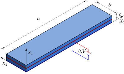
Refer to caption
Figure 5: Problem setting

The ratio between length a𝑎a, width b𝑏b, and height c𝑐c of the EAP are taken as c=a/50𝑐𝑎50c=a/50, b=a/6𝑏𝑎6b=a/6. The sample, depicted in Figure 5, is clamped at one end and is loaded by the application of electric potential in the electrodes in the bottom and in the middle of the height. Δφ=Λhμ1/ε1Δ𝜑Λsubscript𝜇1subscript𝜀1\Delta\varphi=\Lambda h\sqrt{\mu_{1}/\varepsilon_{1}} where ΛΛ\Lambda is a loading parameter, and μ1subscript𝜇1\mu_{1} and ε𝜀\varepsilon are material parameters, see the model below and Table 5. The calculations are performed using the second, i.e., mixed Hu–Washizu variational principle, see Appendix 7.3 for more details. In addition, two different material models are considered. Symmetry 𝒟hsubscript𝒟\mathcal{D}_{\infty h}, applicable to electroactive polymers, is assumed in both cases.

5.2.1 Model 1: 𝒜𝒜\mathcal{A}-polyconvex constitutive law

The energy is constructed to be 𝒜𝒜\mathcal{A}-polyconvex meaning that it is composed of 𝒜𝒜\mathcal{A}-polyconvex invariants only. The proposed model is defined through the energy written as

e¯𝒟h,1(𝑭,𝑫0,𝑴)subscript¯𝑒subscript𝒟1𝑭subscript𝑫0𝑴\displaystyle\bar{e}_{\mathcal{D}_{\infty h},1}(\boldsymbol{F},\boldsymbol{D}_{0},\boldsymbol{M}) =e¯1(𝑭)+e¯2(𝑭,𝑴)+e¯3(𝑭,𝑫0)+e¯4(𝑭,𝑫0,𝑴)absentsubscript¯𝑒1𝑭subscript¯𝑒2𝑭𝑴subscript¯𝑒3𝑭subscript𝑫0subscript¯𝑒4𝑭subscript𝑫0𝑴\displaystyle=\bar{e}_{1}(\boldsymbol{F})+\bar{e}_{2}(\boldsymbol{F},\boldsymbol{M})+\bar{e}_{3}(\boldsymbol{F},\boldsymbol{D}_{0})+\bar{e}_{4}(\boldsymbol{F},\boldsymbol{D}_{0},\boldsymbol{M}) (5.15a)
e¯1(𝑭)subscript¯𝑒1𝑭\displaystyle\bar{e}_{1}(\boldsymbol{F}) =μ12I1dev(𝑭)+μ22I2,poldev(𝑭)+λ2(I3(𝑭)1)2absentsubscript𝜇12superscriptsubscript𝐼1dev𝑭subscript𝜇22superscriptsubscript𝐼2poldev𝑭𝜆2superscriptsubscript𝐼3𝑭12\displaystyle=\frac{\mu_{1}}{2}I_{1}^{\text{dev}}(\boldsymbol{F})+\frac{\mu_{2}}{2}I_{2,\text{pol}}^{\text{dev}}(\boldsymbol{F})+\frac{\lambda}{2}(I_{3}(\boldsymbol{F})-1)^{2} (5.15b)
e¯2(𝑭,𝑴)subscript¯𝑒2𝑭𝑴\displaystyle\bar{e}_{2}(\boldsymbol{F},\boldsymbol{M}) =μ32αI4α(𝑭,𝑴)+μ32βI5β(𝑭,𝑴)μ3lnI3(𝑭)absentsubscript𝜇32𝛼superscriptsubscript𝐼4𝛼𝑭𝑴subscript𝜇32𝛽superscriptsubscript𝐼5𝛽𝑭𝑴subscript𝜇3lnsubscript𝐼3𝑭\displaystyle=\frac{\mu_{3}}{2\alpha}I_{4}^{\alpha}(\boldsymbol{F},\boldsymbol{M})+\frac{\mu_{3}}{2\beta}I_{5}^{\beta}(\boldsymbol{F},\boldsymbol{M})-\mu_{3}{\rm ln}I_{3}(\boldsymbol{F}) (5.15c)
e¯3(𝑭,𝑫0)subscript¯𝑒3𝑭subscript𝑫0\displaystyle\bar{e}_{3}(\boldsymbol{F},\boldsymbol{D}_{0}) =12ε1I7(𝑭,𝑫0)I3(𝑭)+12ε2I6(𝑫0)absent12subscript𝜀1subscript𝐼7𝑭subscript𝑫0subscript𝐼3𝑭12subscript𝜀2subscript𝐼6subscript𝑫0\displaystyle=\frac{1}{2\varepsilon_{1}}\frac{I_{7}(\boldsymbol{F},\boldsymbol{D}_{0})}{I_{3}(\boldsymbol{F})}+\frac{1}{2\varepsilon_{2}}I_{6}(\boldsymbol{D}_{0}) (5.15d)
e¯4(𝑫0)subscript¯𝑒4subscript𝑫0\displaystyle\bar{e}_{4}(\boldsymbol{D}_{0}) =12ε3K1𝒟h(𝑫0)absent12subscript𝜀3superscriptsubscript𝐾1subscript𝒟subscript𝑫0\displaystyle=\frac{1}{2\varepsilon_{3}}K_{1}^{\mathcal{D}_{\infty h}}(\boldsymbol{D}_{0}) (5.15e)
Refer to caption Refer to caption Refer to caption
Figure 6: Deformation of an EAP with different fiber alignment, columns from left to right correspond to 𝑴=[100]T𝑴superscriptmatrix100𝑇\boldsymbol{M}=\begin{bmatrix}1&0&0\end{bmatrix}^{T}, with the snapshots corresponds to loading parameter Λ=(0,10,15,30,60)Λ010153060\Lambda=(0,10,15,30,60); 𝑴=[1/21/20]T𝑴superscriptmatrix12120𝑇\boldsymbol{M}=\begin{bmatrix}1/\sqrt{2}&1/\sqrt{2}&0\end{bmatrix}^{T}, Λ=(0,5,15,20,30,45)Λ0515203045\Lambda=(0,5,15,20,30,45), and 𝑴=[010]T𝑴superscriptmatrix010𝑇\boldsymbol{M}=\begin{bmatrix}0&1&0\end{bmatrix}^{T}, Λ=(0,5,10,15,20,30)Λ0510152030\Lambda=(0,5,10,15,20,30). Contour plots in the first row displays deformation gradient component F22subscript𝐹22F_{22}, the second row displays electric displacement component (D0)zsubscriptsubscript𝐷0𝑧(D_{0})_{z}, and the last row displays minimal value of minor of acoustic tensor normalized by μ1subscript𝜇1\mu_{1}.

Of course, to assure 𝒜𝒜\mathcal{A}-polyconvexity of the model, positive material constants have to be chosen, which is a reasonable physical requirement leading also to coercivity. The material constants used in the following simulation are presented in Table 7.

Table 5: Material properties for Material model 1
μ1subscript𝜇1\mu_{1} μ2subscript𝜇2\mu_{2} μ3subscript𝜇3\mu_{3} λ𝜆\lambda ε1subscript𝜀1\varepsilon_{1} ε2subscript𝜀2\varepsilon_{2} ε3subscript𝜀3\varepsilon_{3}
1×1051superscript1051\times 10^{5} 1.0μ11.0subscript𝜇11.0\mu_{1} 1.0μ11.0subscript𝜇11.0\mu_{1} 103×μ1superscript103subscript𝜇110^{3}\times\mu_{1} 9.6ε09.6subscript𝜀09.6\varepsilon_{0} 2.88ε02.88subscript𝜀02.88\varepsilon_{0} 1.92ε01.92subscript𝜀01.92\varepsilon_{0}

We study three samples with fibre alignment of 0superscript00^{\circ}, 45superscript4545^{\circ}, and 90superscript9090^{\circ} and evaluate the influence of the fibre orientation upon the electrical loading. The three aforementioned fiber orientations corresponds to 𝑴0=[100]Tsubscript𝑴0superscriptmatrix100𝑇\boldsymbol{M}_{0}=\begin{bmatrix}1&0&0\end{bmatrix}^{T}, 𝑴45=[1/21/20]Tsubscript𝑴45superscriptmatrix12120𝑇\boldsymbol{M}_{45}=\begin{bmatrix}1/\sqrt{2}&1/\sqrt{2}&0\end{bmatrix}^{T}, and 𝑴90=[010]Tsubscript𝑴90superscriptmatrix010𝑇\boldsymbol{M}_{90}=\begin{bmatrix}0&1&0\end{bmatrix}^{T} respectively. The results of simulation are depicted in Figure 6 showing clearly that design of fibers alignment substantially influence response of an EAP leading to bending, twisting, or combined modes of deformation. Therefore, the computational approach can be used to carefully tailor fiber orientation to obtain response of an EAP required for a specific application.

5.2.2 Model 2: Non 𝒜𝒜\mathcal{A}-polyconvex constitutive law

In the previous example, we have examined the behaviour of a fibre-reinforced EAP with a constitutive law composed of 𝒜𝒜\mathcal{A}-polyconvex invariants. However, the model does not contain electro-mechanical coupling of the fibres described by invariant K2𝒟hsuperscriptsubscript𝐾2subscript𝒟K_{2}^{\mathcal{D}_{\infty h}}. The model from the previous section is enhanced as

e¯𝒟h,2(𝑭,𝑫0,𝑴)=e¯𝒟h,1(𝑭,𝑫0,𝑴)+12ε4K2𝒟h(𝑭,𝑫0,𝑴)subscript¯𝑒subscript𝒟2𝑭subscript𝑫0𝑴subscript¯𝑒subscript𝒟1𝑭subscript𝑫0𝑴12subscript𝜀4superscriptsubscript𝐾2subscript𝒟𝑭subscript𝑫0𝑴\displaystyle\bar{e}_{\mathcal{D}_{\infty h},2}(\boldsymbol{F},\boldsymbol{D}_{0},\boldsymbol{M})=\bar{e}_{\mathcal{D}_{\infty h},1}(\boldsymbol{F},\boldsymbol{D}_{0},\boldsymbol{M})+\frac{1}{2\varepsilon_{4}}K_{2}^{\mathcal{D}_{\infty h}}(\boldsymbol{F},\boldsymbol{D}_{0},\boldsymbol{M}) (5.16)

Note that coupled electro-mechanical behaviour of fibres is often neglected see, e.g., [1, 3].

Since the model contains a non 𝒜𝒜\mathcal{A}-polyconvex contribution, it is difficult to prove the 𝒜𝒜\mathcal{A}-polyconvex of the model. Therefore, a possible loss of rank-one convexity is investigated for the case with fixed fiber orientation defined by 𝑴=[1/31/31/3]T𝑴superscriptmatrix131313𝑇\boldsymbol{M}=\begin{bmatrix}1/\sqrt{3}&1/\sqrt{3}&1/\sqrt{3}\end{bmatrix}^{T}, and material parameter ε4=19.2ε0subscript𝜀419.2subscript𝜀0\varepsilon_{4}=19.2\varepsilon_{0}.

The loss of rank-one convexity, i.e., ellipticity can be detected through evaluation of the minors of the acoustic tensor (3.14). However, evaluation of ellipticity loss is computationally demanding and not practical for real three-dimensional simulations. Note that several efficient strategies for the detection of loss of ellipticity have been proposed, see, e.g., [2] and references therein.

It is well known that homogenization of fibre-reinforced composites with the matrix and fibres described by polyconvex material laws does not generally lead to a polyconvex model at the macroscale, i.e., polyconvexity is not preserved by homogenization [26, 11]. It can be demonstrated that the loss of polyconvexity of fibre-reinforced elastomers has a clear physical meaning of a long wave-length instability [87].

The results of the simulation for three levels of ΔφΔ𝜑\Delta\varphi are shown in Figure 7. The contour plots display values of the minimal minor of the acoustic tensor normalized by μ1subscript𝜇1\mu_{1}. The results in case (a) show only positive values of the minor. The value is approaching zero in one element in case (b), and negative values can be detected in case (c), meaning that the rank-one convexity has been lost. The loss of rank-one convexity proves that the proposed energy (5.16) is not 𝒜𝒜\mathcal{A}-polyconvex. Even though the loss of rank-one convexity indicates that the governing equations of the electro-mechanical problem become ill-posed and the simulation should be terminated, the evolution of loss of ellipticity is further demonstrated in Figures 7(d).

(a) (b)
Refer to caption Refer to caption
(c) (d)
Refer to caption Refer to caption
Figure 7: Deformation of an EAP reinforced with fibers in direction 𝑴=[1/31/31/3]T𝑴superscriptmatrix131313𝑇\boldsymbol{M}=\begin{bmatrix}1/\sqrt{3}&1/\sqrt{3}&1/\sqrt{3}\end{bmatrix}^{T} for four levels of loading parameter, namely, Λ=(40,44,47,49)Λ40444749\Lambda=(40,44,47,49). Contour plots display minimal minor of the acoustic tensor normalized by μ1subscript𝜇1\mu_{1}. The negative value of a minor of the acoustic tensor means that rank-one convexity has been lost.

5.3 Numerical example 3

The objectives of this example are to:

  • 1.

    Detect the onset of instabilities on a rank-one DE laminated composite square membrane.

  • 2.

    Observe the different buckling patterns in terms of the preferred orientation of transverse isotropy.

The geometry for this numerical example is given by a square membrane of side l=0.06𝑙0.06l=0.06 m and thickness h=0.0010.001h=0.001 m, clamped along all its side faces, as represented in Figure 8. The membrane is subjected to a prescribed electric surface charge on its base while grounded to zero potential on its topside. Geometrical and Finite Element simulation parameters are presented in Table 6. Q3𝑄3Q3 Finite Elements are used to interpolate both displacement and electric potential, being 104,188104188104,188 the total number of degrees of freedom, and the surface charge is applied incrementally, being Λ[0,1]Λ01\Lambda\in[0,1] the load factor. The two-field variational formulation ΠΨ(ϕ,φ)subscriptΠΨbold-italic-ϕ𝜑\Pi_{\Psi}\left(\boldsymbol{\phi},\varphi\right) in equation (2.27) has been considered using the aforementioned Finite Element discretisation. A volumetric force acting along the positive 0X30subscript𝑋30X_{3} axis of value 101010, Nkg1Nsuperscriptkg1\text{N}\cdot\text{kg}^{-1} is considered.

Refer to caption
Figure 8: Numerical example 4. Geometry and boundary conditions.
Geometrical parameters l𝑙l 0.060.060.06 m Simulation parameters Nxsubscript𝑁𝑥N_{x} 606060
hh 0.0010.0010.001 m Nysubscript𝑁𝑦N_{y} 606060
Nzsubscript𝑁𝑧N_{z} 222
Electric charge ω0subscript𝜔0\omega_{0} 0.020.020.02 C/m2Csuperscriptm2\text{C}/\text{m}^{2} Newton tolerance 106superscript10610^{-6}
Table 6: Numerical example 4. Geometrical and simulation parameters.

A similar study was conducted in [61, 62], where a squared membrane, made of a rank-one laminated DE, was subjected to electrical stimuli in order to observe the development of instabilities as it deforms. In this work, we consider the transversely isotropic constitutive model given in equation (5.15). The material parameters featuring in the model can be found in Table 7.

Table 7: Material properties for example 4
μ1subscript𝜇1\mu_{1} μ2subscript𝜇2\mu_{2} μ3subscript𝜇3\mu_{3} λ𝜆\lambda ε1subscript𝜀1\varepsilon_{1} ε2subscript𝜀2\varepsilon_{2} ε3subscript𝜀3\varepsilon_{3}
1×1051superscript1051\times 10^{5} 1.0μ11.0subscript𝜇11.0\mu_{1} 1.0μ11.0subscript𝜇11.0\mu_{1} 103×μ1superscript103subscript𝜇110^{3}\times\mu_{1} 9.6ε09.6subscript𝜀09.6\varepsilon_{0} 2.88ε02.88subscript𝜀02.88\varepsilon_{0} 1.92ε01.92subscript𝜀01.92\varepsilon_{0}

With regards to the preferred direction 𝑴𝑴\boldsymbol{M}, six values have been considered (see Figure (9)). The electrically induced deformation pattern attained by the elastomeric material is indeed highly influenced by the preferred direction 𝑴𝑴\boldsymbol{M}, as it can be clearly appreciated from Figure 9. Naturally, this influence is also reflected in the contour plot pressure distribution over the elastomeric material, as shown in Figure 10.
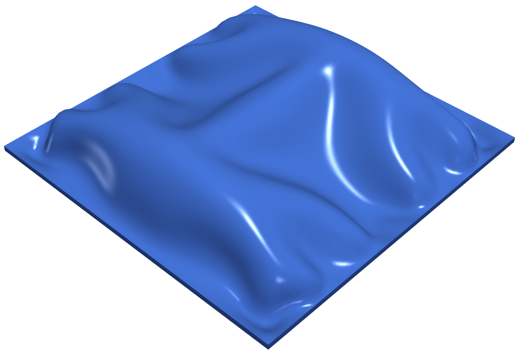
Refer to caption Refer to caption
(a) (b)
Refer to caption Refer to caption
(c) (d)
Refer to caption Refer to caption
(e) (f)
Figure 9: Electrically induced buckling for numerical example 4 for a value of the accumulated load factor ΛΛ\Lambda of Λ=0.4Λ0.4\Lambda=0.4. Different preferred directions 𝑴𝑴\boldsymbol{M}, spherically parametrised according to 𝑴=[cosθsin(ϕ)sinθsin(ϕ)cos(ϕ)]T𝑴superscriptmatrix𝜃italic-ϕ𝜃italic-ϕitalic-ϕ𝑇\boldsymbol{M}=\begin{bmatrix}\cos{\theta}\sin(\phi)&\sin{\theta}\sin(\phi)&\cos(\phi)\end{bmatrix}^{T}, with (θ,ϕ)𝜃italic-ϕ(\theta,\phi): (a) (0,0)00(0,0); (b) (π/8,0)𝜋80(\pi/8,0); (c) (π/4,0)𝜋40(\pi/4,0); (d) (3π/8,0)3𝜋80(3\pi/8,0); (e) (π/2,0)𝜋20(\pi/2,0); (f) (π/4,π/4)𝜋4𝜋4(\pi/4,\pi/4).
Refer to caption Refer to caption
(a) (b)
Refer to caption Refer to caption
(c) (d)
Refer to caption Refer to caption
(e) (f)
Refer to caption
Figure 10: Electrically induced buckling for numerical example 4 for a value of the accumulated load factor ΛΛ\Lambda of Λ=0.4Λ0.4\Lambda=0.4. Contour plot distribution of hydrostatic pressure p=tr(J1𝑷𝑭T)𝑝trsuperscript𝐽1𝑷superscript𝑭𝑇p=\text{tr}(J^{-1}\boldsymbol{P}\boldsymbol{F}^{T}). Different preferred directions 𝑴𝑴\boldsymbol{M}, spherically parametrised according to 𝑴=[cosθsin(ϕ)sinθsin(ϕ)cos(ϕ)]T𝑴superscriptmatrix𝜃italic-ϕ𝜃italic-ϕitalic-ϕ𝑇\boldsymbol{M}=\begin{bmatrix}\cos{\theta}\sin(\phi)&\sin{\theta}\sin(\phi)&\cos(\phi)\end{bmatrix}^{T}, with (θ,ϕ)𝜃italic-ϕ(\theta,\phi): (a) (0,0)00(0,0); (b) (π/8,0)𝜋80(\pi/8,0); (c) (π/4,0)𝜋40(\pi/4,0); (d) (3π/8,0)3𝜋80(3\pi/8,0); (e) (π/2,0)𝜋20(\pi/2,0); (f) (π/4,π/4)𝜋4𝜋4(\pi/4,\pi/4).

6 Conclusions

This paper has presented a phenomenological invariant-based polyconvex transversely isotropic framework for the simulation of EAPs at large strains. Taking inspiration from the pioneering work by Schröeder and Neff [81], the research builds on previous work by some of authors [40] for the description of polyconvex isotropic EAPS and enhances it for the modelling of EAPs equipped with an internal transversely isotropic crystallographic structure of the selected types 𝒟hsubscript𝒟\mathcal{D}_{\infty h} and 𝒞subscript𝒞\mathcal{C}_{\infty} [33]. The paper also bridges the gap between the work developed by Šilhavý [85] regarding the existence of minimisers and other key computational requirements, such as, rank-one convexity and ellipticity [40], the latter necessary to prevent the appearance of spurious mesh-dependent results.

Three numerical examples are included in order to demonstrate the effect that the anisotropic orientation and the contrast of material properties, as well as the level of deformation and electric field, have upon the response of the EAP when subjected to large three-dimensional stretching, bending, and torsion, including the possible development of wrinkling. Whilst the first example focuses on an academic type of problem, that is, homogeneous deformation, the latter two explore the use of Finite Element discretisations to monitor the response of the framework in realistic three-dimensional in-silico simulations. This manuscript paves the way towards the in-silico simulation of novel soft robotics components made up of predominantly dominant transversely isotropic Electro-Active Polymers (EAPs). Crucially, this type of phenomenologically based model can be enhanced and informed via the use of laboratory data experiments, the up-scaling of computational homogeneisation of complex micro-architecture EAPs, or even the use of Artificial Intelligence type of approaches. These will be the focus of our future work.
 
Declaration of competing interests
The authors declare that they have no known competing financial interests or personal relationships that could have appeared to influence the work reported in this paper.
 
Acknowledgments
MH and MK acknowledge support by the Czech Science Foundation (EXPRO project No. 19-26143X), AJG acknowledges the financial support received through the European Training Network Protechtion (Project ID: 764636).

7 Appendices

7.1 Ellipticity and acoustic tensor

As shown in [66], the unknown fields ϕbold-italic-ϕ\boldsymbol{\phi} and 𝑫0subscript𝑫0\boldsymbol{D}_{0} can be written as a perturbation with respect to equilibrium states ϕeqsuperscriptbold-italic-ϕeq\boldsymbol{\phi}^{\text{eq}} and 𝑫0eqsuperscriptsubscript𝑫0eq\boldsymbol{D}_{0}^{\text{eq}}, respectively, by means of the addition of transient travelling (plane) wave functions as

ϕ=ϕeq+𝒖f(α);𝑫0=𝑫0eq+𝑽g(α);α=𝑿𝑽ct,formulae-sequencebold-italic-ϕsuperscriptbold-italic-ϕeq𝒖𝑓𝛼formulae-sequencesubscript𝑫0superscriptsubscript𝑫0eqsubscript𝑽perpendicular-to𝑔𝛼𝛼𝑿𝑽𝑐𝑡\boldsymbol{\phi}=\boldsymbol{\phi}^{\text{eq}}+\boldsymbol{u}f(\alpha);\qquad\boldsymbol{D}_{0}=\boldsymbol{D}_{0}^{\text{eq}}+\boldsymbol{V}_{\perp}g(\alpha);\qquad\alpha=\boldsymbol{X}\cdot\boldsymbol{V}-ct, (7.1)

where 𝑽𝑽\boldsymbol{V} represents the polarisation vector of the travelling wave, c𝑐c the associated speed of propagation of the perturbation with amplitudes 𝒖𝒖\boldsymbol{u} and 𝑽subscript𝑽perpendicular-to\boldsymbol{V}_{\perp} and f𝑓f and g𝑔g two arbitrary α𝛼\alpha-scalar functions. Substitution of above ansatzs into (2.1) and (2.6a), respectively, results in

𝑭𝑭\displaystyle\boldsymbol{F} =0ϕeq=𝑭eq+(𝒖𝑽)f(α);absentsubscriptsubscriptbold-∇0superscriptbold-italic-ϕeqabsentsuperscript𝑭eqtensor-product𝒖𝑽superscript𝑓𝛼\displaystyle=\underbrace{\boldsymbol{\nabla}_{0}\boldsymbol{\phi}^{\text{eq}}}_{=\boldsymbol{F}^{\text{eq}}}+(\boldsymbol{u}\otimes\boldsymbol{V})f^{\prime}(\alpha); (7.2a)
DIV𝑫0ρ0DIVsubscript𝑫0subscript𝜌0\displaystyle\text{DIV}\boldsymbol{D}_{0}-\rho_{0} =DIV𝑫0eqρ0=0+(𝑽𝑽)g(α)=0,absentsubscriptDIVsubscriptsuperscript𝑫eq0subscript𝜌0absent0subscript𝑽perpendicular-to𝑽superscript𝑔𝛼0\displaystyle=\underbrace{\text{DIV}\boldsymbol{D}^{\text{eq}}_{0}-\rho_{0}}_{=0}+\left(\boldsymbol{V}_{\perp}\cdot\boldsymbol{V}\right)g^{\prime}(\alpha)=0, (7.2b)

hence, 𝑽subscript𝑽perpendicular-to\boldsymbol{V}_{\perp} must be orthogonal to 𝑽𝑽\boldsymbol{V}. Linearisation of the first Piola-Kirchhoff stress tensor 𝑷𝑷\boldsymbol{P} and the electric field 𝑬0subscript𝑬0\boldsymbol{E}_{0} about equilibrium states 𝑷eq=𝑷(𝓤eq)superscript𝑷eq𝑷superscript𝓤eq\boldsymbol{P}^{\text{eq}}=\boldsymbol{P}(\boldsymbol{\mathcal{U}}^{\text{eq}}) and 𝑬0eq=𝑬0(𝓤eq)superscriptsubscript𝑬0eqsubscript𝑬0superscript𝓤eq\boldsymbol{E}_{0}^{\text{eq}}=\boldsymbol{E}_{0}(\boldsymbol{\mathcal{U}}^{\text{eq}}), with 𝓤eq=(𝑭eq,𝑫0eq)superscript𝓤eqsuperscript𝑭eqsuperscriptsubscript𝑫0eq\boldsymbol{\mathcal{U}}^{\text{eq}}=(\boldsymbol{F}^{\text{eq}},\boldsymbol{D}_{0}^{\text{eq}}), gives

[𝑷𝑬0]=[𝑷eq𝑬0eq]+[𝓒e𝓠T𝓠𝜽][:(𝒖𝑽)f(α)𝑽g(α)].delimited-[]matrix𝑷subscript𝑬0delimited-[]matrixsuperscript𝑷eqsuperscriptsubscript𝑬0eqdelimited-[]matrixsubscript𝓒𝑒superscript𝓠𝑇𝓠𝜽delimited-[]matrix:absenttensor-product𝒖𝑽superscript𝑓𝛼subscript𝑽perpendicular-to𝑔𝛼\left[\begin{matrix}\boldsymbol{P}\\ \boldsymbol{E}_{0}\end{matrix}\right]=\left[\begin{matrix}\boldsymbol{P}^{\text{eq}}\\ \boldsymbol{E}_{0}^{\text{eq}}\end{matrix}\right]+\left[\begin{matrix}\boldsymbol{\mathcal{C}}_{e}&\boldsymbol{\mathcal{Q}}^{T}\\ \boldsymbol{\mathcal{Q}}&\boldsymbol{\mathcal{\theta}}\\ \end{matrix}\right]\left[\begin{matrix}:(\boldsymbol{u}\otimes\boldsymbol{V})f^{\prime}(\alpha)\\ \boldsymbol{V}_{\perp}g(\alpha)\end{matrix}\right]. (7.3)

Substitution of (7.3) into (2.3) and into Faraday’s law (2.5a)151515In this case, use is made of the more generic expression for Faraday’s law, namely CURL𝑬0=𝟎CURLsubscript𝑬00\text{CURL}\boldsymbol{E}_{0}=\boldsymbol{0}. gives

DIV𝑷+𝒃0DIV𝑷subscript𝒃0\displaystyle\text{DIV}\boldsymbol{P}+\boldsymbol{b}_{0} =DIV𝑷eq+𝒃0=𝟎+𝓒𝒆,𝑽𝑽𝒖f′′(α)+𝓠𝑽T𝑽g(α)ρRc2𝒖f′′(α);absentsubscriptDIVsuperscript𝑷eqsubscript𝒃0absent0subscriptsubscript𝓒𝒆𝑽𝑽𝒖superscript𝑓′′𝛼superscriptsubscript𝓠𝑽𝑇subscript𝑽perpendicular-tosuperscript𝑔𝛼subscript𝜌𝑅superscript𝑐2𝒖superscript𝑓′′𝛼\displaystyle=\underbrace{\text{DIV}\boldsymbol{P}^{\text{eq}}+\boldsymbol{b}_{0}}_{=\boldsymbol{0}}+\underbrace{\boldsymbol{\mathcal{C}_{e,\boldsymbol{V}\boldsymbol{V}}}\;\boldsymbol{u}f^{\prime\prime}(\alpha)+\boldsymbol{\mathcal{Q}_{\boldsymbol{V}}}^{T}\boldsymbol{V}_{\perp}g^{\prime}(\alpha)}_{\rho_{R}c^{2}\boldsymbol{u}f^{\prime\prime}(\alpha)}; (7.4a)
CURL𝑬0CURLsubscript𝑬0\displaystyle\text{CURL}\boldsymbol{E}_{0} =CURL𝑬0eq=𝟎+𝓔𝑽[𝓠𝑽𝒖f′′(α)+𝜽𝑽g(α)]=𝟎,absentsubscriptCURLsuperscriptsubscript𝑬0eqabsent0subscript𝓔𝑽delimited-[]subscript𝓠𝑽𝒖superscript𝑓′′𝛼𝜽subscript𝑽perpendicular-tosuperscript𝑔𝛼0\displaystyle=\underbrace{\text{CURL}\boldsymbol{E}_{0}^{\text{eq}}}_{=\boldsymbol{0}}+\boldsymbol{\mathcal{E}_{V}}\left[\boldsymbol{\mathcal{Q}_{\boldsymbol{V}}}\;\boldsymbol{u}f^{\prime\prime}(\alpha)+\boldsymbol{\theta}\;\boldsymbol{V}_{\perp}g^{\prime}(\alpha)\right]=\boldsymbol{0}, (7.4b)

where

[𝓒𝒆,𝑽𝑽]ij=𝒞e,iIjJVIVJ,[𝓠𝑽]Ij=𝒬IjJVJ,[𝓔𝑽]IJ=IJKVK,formulae-sequencesubscriptdelimited-[]subscript𝓒𝒆𝑽𝑽𝑖𝑗subscript𝒞𝑒𝑖𝐼𝑗𝐽subscript𝑉𝐼subscript𝑉𝐽formulae-sequencesubscriptdelimited-[]subscript𝓠𝑽𝐼𝑗subscript𝒬𝐼𝑗𝐽subscript𝑉𝐽subscriptdelimited-[]subscript𝓔𝑽𝐼𝐽subscript𝐼𝐽𝐾subscript𝑉𝐾\left[\boldsymbol{\mathcal{C}_{e,\boldsymbol{V}\boldsymbol{V}}}\right]_{ij}=\mathcal{C}_{e,iIjJ}V_{I}V_{J},\qquad\left[\boldsymbol{\mathcal{Q}_{\boldsymbol{V}}}\right]_{Ij}=\mathcal{Q}_{IjJ}V_{J},\qquad\left[\boldsymbol{\mathcal{E}_{V}}\right]_{IJ}=\mathcal{E}_{IJK}V_{K}, (7.5)

where IJKsubscript𝐼𝐽𝐾\mathcal{E}_{IJK} denotes the Levi-Civita third-order tensor. Notice that the last underbraced term on the right-hand side of (7.4a) is identified with the inertial term corresponding to the acceleration effect with ρRsubscript𝜌𝑅\rho_{R} the density of the electroactive material. Naturally, a satisfaction of (7.4b) requires the vector within squared brackets to be collinear to 𝑽𝑽\boldsymbol{V}, which permits to obtain

𝑽g(α)=𝜽1[β𝑽𝑽𝓠𝑽𝒖f′′(α)]subscript𝑽perpendicular-tosuperscript𝑔𝛼superscript𝜽1delimited-[]subscript𝛽𝑽𝑽subscript𝓠𝑽𝒖superscript𝑓′′𝛼\boldsymbol{V}_{\perp}g^{\prime}(\alpha)=\boldsymbol{\theta}^{-1}\left[\beta_{\boldsymbol{V}}\boldsymbol{V}-\boldsymbol{\mathcal{Q}_{\boldsymbol{V}}}\;\boldsymbol{u}f^{\prime\prime}(\alpha)\right] (7.6)

with β𝑽subscript𝛽𝑽\beta_{\boldsymbol{V}} a proportionality constant, which can be easily computed from (7.6) by projecting both sides of the equation against 𝑽𝑽\boldsymbol{V}, rendering

β𝑽=𝑽(𝜽1𝓠𝑽)𝒖𝑽𝜽1𝑽f′′(α).subscript𝛽𝑽𝑽superscript𝜽1subscript𝓠𝑽𝒖𝑽superscript𝜽1𝑽superscript𝑓′′𝛼\beta_{\boldsymbol{V}}=\frac{\boldsymbol{V}\cdot\left(\boldsymbol{\theta}^{-1}\boldsymbol{\mathcal{Q}_{\boldsymbol{V}}}\right)\boldsymbol{u}}{\boldsymbol{V}\cdot\boldsymbol{\theta}^{-1}\boldsymbol{V}}f^{\prime\prime}(\alpha). (7.7)

Substitution of (7.7) into (7.6) and after some algebraic manipulation gives

𝑽g(α)=𝜽1𝛀𝓠𝑽f′′(α);𝛀=[𝑽𝜽1𝑽𝑽𝜽1𝑽𝑰].formulae-sequencesubscript𝑽perpendicular-tosuperscript𝑔𝛼superscript𝜽1𝛀subscript𝓠𝑽superscript𝑓′′𝛼𝛀delimited-[]tensor-product𝑽superscript𝜽1𝑽𝑽superscript𝜽1𝑽𝑰\boldsymbol{V}_{\perp}g^{\prime}(\alpha)=\boldsymbol{\theta}^{-1}\boldsymbol{\Omega}\boldsymbol{\mathcal{Q}_{\boldsymbol{V}}}f^{\prime\prime}(\alpha);\qquad\boldsymbol{\Omega}=\left[\frac{\boldsymbol{V}\otimes\boldsymbol{\theta}^{-1}\boldsymbol{V}}{\boldsymbol{V}\cdot\boldsymbol{\theta}^{-1}\boldsymbol{V}}-\boldsymbol{I}\right]. (7.8)

Substitutions of above equation (7.8) into (7.4a), results in

𝑸𝒖=ρc2𝒖;𝑸=𝓒𝒆,𝑽𝑽+𝓠𝑽T𝜽1𝛀𝓠𝑽,formulae-sequence𝑸𝒖𝜌superscript𝑐2𝒖𝑸subscript𝓒𝒆𝑽𝑽superscriptsubscript𝓠𝑽𝑇superscript𝜽1𝛀subscript𝓠𝑽\boldsymbol{Q}\boldsymbol{u}=\rho c^{2}\boldsymbol{u};\qquad\boldsymbol{Q}=\boldsymbol{\mathcal{C}_{e,\boldsymbol{V}\boldsymbol{V}}}+\boldsymbol{\mathcal{Q}_{\boldsymbol{V}}}^{T}\boldsymbol{\theta}^{-1}\boldsymbol{\Omega}\boldsymbol{\mathcal{Q}_{\boldsymbol{V}}}, (7.9)

where 𝑸𝑸\boldsymbol{Q} is the so-called electro-mechanical acoustic tensor which is a function of the constitutive tensors 𝓒esubscript𝓒𝑒\boldsymbol{\mathcal{C}}_{e}, 𝓠𝓠\boldsymbol{\mathcal{Q}}, 𝜽𝜽\boldsymbol{\theta} (dependent upon the state of electro-deformation), as well as the polarisation orientation 𝑽𝑽\boldsymbol{V}. A reasonable physical requirement is that of the existence of real wave speeds, which requires the positive semi-definiteness of the acoustic tensor 𝑸𝑸\boldsymbol{Q}, that is,

𝒖𝑸𝒖0;𝓤,𝒖,𝑽.𝒖𝑸𝒖0for-all𝓤𝒖𝑽\boldsymbol{u}\cdot\boldsymbol{Q}\boldsymbol{u}\geq 0;\qquad\forall\,\boldsymbol{\mathcal{U}},\boldsymbol{u},\boldsymbol{V}. (7.10)

7.2 Polyconvex invariants

The purpose here is prove that invariant I8polsuperscriptsubscript𝐼8polI_{8}^{\text{pol}} is convex with respect to 𝑯𝑯\boldsymbol{H} and 𝑫0subscript𝑫0\boldsymbol{D}_{0}. For that, let us compute D2I8pol[δ𝑯,δ𝑫0;δ𝑯,δ𝑫0]superscript𝐷2superscriptsubscript𝐼8pol𝛿𝑯𝛿subscript𝑫0𝛿𝑯𝛿subscript𝑫0D^{2}I_{8}^{\text{pol}}[\delta\boldsymbol{H},\delta\boldsymbol{D}_{0};\delta\boldsymbol{H},\delta\boldsymbol{D}_{0}], i.e.

D2I8pol[δ𝑯,δ𝑫0;δ𝑯,δ𝑫0]superscript𝐷2superscriptsubscript𝐼8pol𝛿𝑯𝛿subscript𝑫0𝛿𝑯𝛿subscript𝑫0\displaystyle D^{2}I_{8}^{\text{pol}}[\delta\boldsymbol{H},\delta\boldsymbol{D}_{0};\delta\boldsymbol{H},\delta\boldsymbol{D}_{0}] =4||𝑯||2||δ𝑯||2+8(𝑯:δ𝑯)2\displaystyle=4||\boldsymbol{H}||^{2}||\delta\boldsymbol{H}||^{2}+8(\boldsymbol{H}:\delta\boldsymbol{H})^{2} (7.11)
+2δ𝑯𝑫0+𝑯δ𝑫02+4𝑯𝑫0δ𝑯δ𝑫02superscriptnorm𝛿𝑯subscript𝑫0𝑯𝛿subscript𝑫024𝑯subscript𝑫0𝛿𝑯𝛿subscript𝑫0\displaystyle+2||\delta\boldsymbol{H}\boldsymbol{D}_{0}+\boldsymbol{H}\delta\boldsymbol{D}_{0}||^{2}+4\boldsymbol{H}\boldsymbol{D}_{0}\cdot\delta\boldsymbol{H}\delta\boldsymbol{D}_{0}
+4𝑫02δ𝑫02+8(𝑫0δ𝑫0)24superscriptnormsubscript𝑫02superscriptnorm𝛿subscript𝑫028superscriptsubscript𝑫0𝛿subscript𝑫02\displaystyle+4||\boldsymbol{D}_{0}||^{2}||\delta\boldsymbol{D}_{0}||^{2}+8(\boldsymbol{D}_{0}\cdot\delta\boldsymbol{D}_{0})^{2}
4𝑯2δ𝑯2+4𝑯𝑫0δ𝑯δ𝑫0+4𝑫02δ𝑫02absent4superscriptnorm𝑯2superscriptnorm𝛿𝑯24𝑯subscript𝑫0𝛿𝑯𝛿subscript𝑫04superscriptnormsubscript𝑫02superscriptnorm𝛿subscript𝑫02\displaystyle\geq 4||\boldsymbol{H}||^{2}||\delta\boldsymbol{H}||^{2}+4\boldsymbol{H}\boldsymbol{D}_{0}\cdot\delta\boldsymbol{H}\delta\boldsymbol{D}_{0}+4||\boldsymbol{D}_{0}||^{2}||\delta\boldsymbol{D}_{0}||^{2}

Application of the Cauchy-Schwarz inequality in the previous equation yields

D2I8pol[δ𝑯,δ𝑫0;δ𝑯,δ𝑫0]superscript𝐷2superscriptsubscript𝐼8pol𝛿𝑯𝛿subscript𝑫0𝛿𝑯𝛿subscript𝑫0\displaystyle D^{2}I_{8}^{\text{pol}}[\delta\boldsymbol{H},\delta\boldsymbol{D}_{0};\delta\boldsymbol{H},\delta\boldsymbol{D}_{0}] 4(𝑯2δ𝑯2𝑯𝑫0δ𝑯δ𝑫0+𝑫02δ𝑫02)absent4superscriptnorm𝑯2superscriptnorm𝛿𝑯2norm𝑯subscript𝑫0norm𝛿𝑯𝛿subscript𝑫0superscriptnormsubscript𝑫02superscriptnorm𝛿subscript𝑫02\displaystyle\geq 4\Big{(}||\boldsymbol{H}||^{2}||\delta\boldsymbol{H}||^{2}-||\boldsymbol{H}\boldsymbol{D}_{0}||||\delta\boldsymbol{H}\delta\boldsymbol{D}_{0}||+||\boldsymbol{D}_{0}||^{2}||\delta\boldsymbol{D}_{0}||^{2}\Big{)} (7.12)

and by definition, the norm of a matrix 𝑯𝑯\boldsymbol{H} verifies that

𝑯𝒗𝑯𝒗norm𝑯𝒗norm𝑯norm𝒗||\boldsymbol{H}\boldsymbol{v}||\leq||\boldsymbol{H}||||\boldsymbol{v}|| (7.13)

for any vector 𝒗𝒗\boldsymbol{v}. Therefore, it is possible to conclude that

D2I8pol[δ𝑯,δ𝑫0;δ𝑯,δ𝑫0]superscript𝐷2superscriptsubscript𝐼8pol𝛿𝑯𝛿subscript𝑫0𝛿𝑯𝛿subscript𝑫0\displaystyle D^{2}I_{8}^{\text{pol}}[\delta\boldsymbol{H},\delta\boldsymbol{D}_{0};\delta\boldsymbol{H},\delta\boldsymbol{D}_{0}] 4(𝑯2δ𝑯2𝑯𝑫0δ𝑯δ𝑫0+𝑫02δ𝑫02)absent4superscriptnorm𝑯2superscriptnorm𝛿𝑯2norm𝑯normsubscript𝑫0norm𝛿𝑯norm𝛿subscript𝑫0superscriptnormsubscript𝑫02superscriptnorm𝛿subscript𝑫02\displaystyle\geq 4\Big{(}||\boldsymbol{H}||^{2}||\delta\boldsymbol{H}||^{2}-||\boldsymbol{H}||||\boldsymbol{D}_{0}||||\delta\boldsymbol{H}||||\delta\boldsymbol{D}_{0}||+||\boldsymbol{D}_{0}||^{2}||\delta\boldsymbol{D}_{0}||^{2}\Big{)} (7.14)
4(𝑯2δ𝑯22𝑯𝑫0δ𝑯δ𝑫0+𝑫02δ𝑫02)absent4superscriptnorm𝑯2superscriptnorm𝛿𝑯22norm𝑯normsubscript𝑫0norm𝛿𝑯norm𝛿subscript𝑫0superscriptnormsubscript𝑫02superscriptnorm𝛿subscript𝑫02\displaystyle\geq 4\Big{(}||\boldsymbol{H}||^{2}||\delta\boldsymbol{H}||^{2}-2||\boldsymbol{H}||||\boldsymbol{D}_{0}||||\delta\boldsymbol{H}||||\delta\boldsymbol{D}_{0}||+||\boldsymbol{D}_{0}||^{2}||\delta\boldsymbol{D}_{0}||^{2}\Big{)}
=4(𝑯δ𝑯𝑫0δ𝑫0)20absent4superscriptnorm𝑯norm𝛿𝑯normsubscript𝑫0norm𝛿subscript𝑫020\displaystyle=4\Big{(}||\boldsymbol{H}||||\delta\boldsymbol{H}||-||\boldsymbol{D}_{0}||||\delta\boldsymbol{D}_{0}||\Big{)}^{2}\geq 0

which therefore, concludes the proof. A similar derivation can be carried out in order to proof convexity with respect to 𝒅𝒅\boldsymbol{d} and 𝑭𝑭\boldsymbol{F} of the polyconvex invariant K2,pol𝒟superscriptsubscript𝐾2polsubscript𝒟K_{2,\text{pol}}^{\mathcal{D}_{\infty}}.

7.3 Finite Element implementation

This Appendix briefly summarises the Finite Element spatial discretisation procedure implemented for the second and third numerical examples. Specifically, we focused on the mixed Hu-Washizu type of variational principle Π~esubscript~Π𝑒\tilde{\Pi}_{e} (2.22), whose stationary conditions yield

DΠ~e[δϕ]𝐷subscript~Π𝑒delimited-[]𝛿bold-italic-ϕ\displaystyle D\tilde{\Pi}_{e}[\delta\boldsymbol{\phi}] =Ω0e𝑭:0δϕdVDΠext[δϕ]=0;:absentsubscriptsubscriptΩ0subscript𝑒𝑭subscriptbold-∇0𝛿bold-italic-ϕ𝑑𝑉𝐷subscriptΠextdelimited-[]𝛿bold-italic-ϕ0\displaystyle=\int_{{\Omega}_{0}}\partial e_{\boldsymbol{F}}:\boldsymbol{\nabla}_{0}\delta\boldsymbol{\phi}\;dV-D\Pi_{\text{ext}}[\delta\boldsymbol{\phi}]=0; (7.15)
DΠ~e[δ𝑫0]𝐷subscript~Π𝑒delimited-[]𝛿subscript𝑫0\displaystyle D\tilde{\Pi}_{e}[\delta\boldsymbol{D}_{0}] =Ω0(e𝑫0+0φ)δ𝑫0𝑑V=0;absentsubscriptsubscriptΩ0subscript𝑒subscript𝑫0subscriptbold-∇0𝜑𝛿subscript𝑫0differential-d𝑉0\displaystyle=\int_{{\Omega}_{0}}(\partial e_{\boldsymbol{D}_{0}}+\boldsymbol{\nabla}_{0}\varphi)\cdot\delta\boldsymbol{D}_{0}\;dV=0;
DΠ~e[δφ]𝐷subscript~Π𝑒delimited-[]𝛿𝜑\displaystyle D\tilde{\Pi}_{e}[\delta\varphi] =Ω0𝑫00δφdVDΠext[δφ]=0,absentsubscriptsubscriptΩ0subscript𝑫0subscriptbold-∇0𝛿𝜑𝑑𝑉𝐷subscriptΠextdelimited-[]𝛿𝜑0\displaystyle=\int_{{\Omega}_{0}}\boldsymbol{D}_{0}\cdot\boldsymbol{\nabla}_{0}\delta\varphi\;dV-D\Pi_{\text{ext}}[\delta\varphi]=0,

where {ϕ,𝑫0,φ}𝕍ϕ¯ϕ×𝕍𝑫0×𝕍φ¯φbold-italic-ϕsubscript𝑫0𝜑subscriptsuperscript𝕍bold-italic-ϕ¯bold-italic-ϕsuperscript𝕍subscript𝑫0subscriptsuperscript𝕍𝜑¯𝜑\{\boldsymbol{\phi},\boldsymbol{D}_{0},\varphi\}\in\mathbb{V}^{\boldsymbol{\phi}}_{\bar{\boldsymbol{\phi}}}\times\mathbb{V}^{\boldsymbol{D}_{0}}\times\mathbb{V}^{\varphi}_{\bar{\varphi}} and with admissible variations {δϕ,δ𝑫0,δφ}𝕍𝟎ϕ×𝕍𝑫0×𝕍0φ𝛿bold-italic-ϕ𝛿subscript𝑫0𝛿𝜑subscriptsuperscript𝕍bold-italic-ϕ0superscript𝕍subscript𝑫0subscriptsuperscript𝕍𝜑0\{\delta\boldsymbol{\phi},\delta\boldsymbol{D}_{0},\delta\varphi\}\in\mathbb{V}^{\boldsymbol{\phi}}_{\boldsymbol{0}}\times\mathbb{V}^{\boldsymbol{D}_{0}}\times\mathbb{V}^{\varphi}_{0}, defined as

𝕍ϕ¯ϕsubscriptsuperscript𝕍bold-italic-ϕ¯bold-italic-ϕ\displaystyle\mathbb{V}^{\boldsymbol{\phi}}_{\bar{\boldsymbol{\phi}}} =\displaystyle= {ϕ:Ω03;[ϕ]iH1(Ω0);J>0;|ϕ=ϕ¯onΩ0u};\displaystyle\begin{Bmatrix}\boldsymbol{\phi}:\Omega_{0}\rightarrow{\mathbb{R}}^{3};\;[\boldsymbol{\phi}]_{i}\in H^{1}(\Omega_{0});\;J>0;\;|\;\boldsymbol{\phi}=\bar{\boldsymbol{\phi}}\;\text{on}\;\partial\Omega_{0}^{u}\end{Bmatrix};
𝕍φ¯φsubscriptsuperscript𝕍𝜑¯𝜑\displaystyle\mathbb{V}^{{\varphi}}_{\bar{\varphi}} =\displaystyle= {φ:Ω0;φH1(Ω0)|φ=φ¯onΩ0φ};matrix:𝜑formulae-sequencesubscriptΩ0𝜑conditionalsuperscript𝐻1subscriptΩ0𝜑¯𝜑onsuperscriptsubscriptΩ0𝜑\displaystyle\begin{Bmatrix}{\varphi}:\Omega_{0}\rightarrow{\mathbb{R}};\;{\varphi}\in H^{1}(\Omega_{0})\;|\;{\varphi}=\bar{{\varphi}}\;\text{on}\;\partial\Omega_{0}^{\varphi}\end{Bmatrix};
𝕍𝑫0superscript𝕍subscript𝑫0\displaystyle\mathbb{V}^{\boldsymbol{D}_{0}} =\displaystyle= {𝑫0:Ω03;𝑫0L2(Ω0)}.matrix:subscript𝑫0formulae-sequencesubscriptΩ0superscript3subscript𝑫0subscript𝐿2subscriptΩ0\displaystyle\begin{Bmatrix}\bm{D}_{0}:\Omega_{0}\rightarrow{\mathbb{R}}^{3};\;\bm{D}_{0}\in L_{2}(\Omega_{0})\end{Bmatrix}.

Further, we apply standard isoparametric Finite Elements and the domain Ω0subscriptΩ0\Omega_{0} is divided into elements and the displacement, electric potential and electric displacement fields are approximated by means of approximation finite element spaces 𝕍ϕ¯,hϕ𝕍ϕ¯ϕsubscriptsuperscript𝕍bold-italic-ϕ¯bold-italic-ϕsubscriptsuperscript𝕍bold-italic-ϕ¯bold-italic-ϕ\mathbb{V}^{\boldsymbol{\phi}}_{\bar{\boldsymbol{\phi}},h}\subset\mathbb{V}^{\boldsymbol{\phi}}_{\bar{\boldsymbol{\phi}}}, Vφ¯,hφVφ¯φsubscriptsuperscript𝑉𝜑¯𝜑subscriptsuperscript𝑉𝜑¯𝜑V^{\varphi}_{\bar{\varphi},h}\subset V^{\varphi}_{\bar{\varphi}}, and Vh𝑫0V𝑫0subscriptsuperscript𝑉subscript𝑫0superscript𝑉subscript𝑫0V^{\boldsymbol{D}_{0}}_{h}\subset V^{\boldsymbol{D}_{0}} defined as

𝕍ϕ¯,hϕsubscriptsuperscript𝕍bold-italic-ϕ¯bold-italic-ϕ\displaystyle\mathbb{V}^{\boldsymbol{\phi}}_{\bar{\boldsymbol{\phi}},h} =\displaystyle= {ϕ:Ω03;ϕ=a=1nnodϕNϕa𝒅ϕa|ϕ=ϕ¯onΩ0u};matrix:bold-italic-ϕformulae-sequencesubscriptΩ0superscript3bold-italic-ϕconditionalsuperscriptsubscript𝑎1subscriptsuperscript𝑛bold-italic-ϕ𝑛𝑜𝑑superscriptsubscript𝑁bold-italic-ϕ𝑎subscriptsuperscript𝒅𝑎bold-italic-ϕbold-italic-ϕ¯bold-italic-ϕonsuperscriptsubscriptΩ0𝑢\displaystyle\begin{Bmatrix}\boldsymbol{\phi}:\Omega_{0}\rightarrow{\mathbb{R}}^{3};\;\boldsymbol{\phi}=\sum_{a=1}^{n^{\boldsymbol{\phi}}_{nod}}N_{\boldsymbol{\phi}}^{a}\boldsymbol{d}^{a}_{\boldsymbol{\phi}}\;|\;\boldsymbol{\phi}=\bar{\boldsymbol{\phi}}\;{\rm on}\;\partial\Omega_{0}^{u}\end{Bmatrix};
Vφ¯,hφsubscriptsuperscript𝑉𝜑¯𝜑\displaystyle V^{\varphi}_{\bar{\varphi},h} =\displaystyle= {φ:Ω03;φ=a=1nnodφNφadφa|φ=φ¯onΩ0φ};matrix:𝜑formulae-sequencesubscriptΩ0superscript3𝜑conditionalsuperscriptsubscript𝑎1subscriptsuperscript𝑛𝜑𝑛𝑜𝑑superscriptsubscript𝑁𝜑𝑎subscriptsuperscript𝑑𝑎𝜑𝜑¯𝜑onsuperscriptsubscriptΩ0𝜑\displaystyle\begin{Bmatrix}{\varphi}:\Omega_{0}\rightarrow{\mathbb{R}}^{3};\;\varphi=\sum_{a=1}^{n^{\varphi}_{nod}}N_{\varphi}^{a}d^{a}_{\varphi}\;|\;\varphi=\bar{\varphi}\;{\rm on}\;\partial\Omega_{0}^{\varphi}\end{Bmatrix};
Vh𝑫0subscriptsuperscript𝑉subscript𝑫0\displaystyle V^{\boldsymbol{D}_{0}}_{h} =\displaystyle= {𝑫0:Ω03;𝑫0=a=1nnodDN𝑫0a𝒅𝑫0a},matrix:subscript𝑫0formulae-sequencesubscriptΩ0superscript3subscript𝑫0superscriptsubscript𝑎1subscriptsuperscript𝑛𝐷𝑛𝑜𝑑superscriptsubscript𝑁subscript𝑫0𝑎subscriptsuperscript𝒅𝑎subscript𝑫0\displaystyle\begin{Bmatrix}\bm{D}_{0}:\Omega_{0}\rightarrow{\mathbb{R}}^{3};\;\bm{D}_{0}=\sum_{a=1}^{n^{D}_{nod}}N_{\boldsymbol{D}_{0}}^{a}\boldsymbol{d}^{a}_{\boldsymbol{D}_{0}}\end{Bmatrix},

where for any field i={ϕ,𝑫0,φ}𝑖matrixbold-italic-ϕsubscript𝑫0𝜑i=\begin{Bmatrix}{{\boldsymbol{\phi}},\boldsymbol{D}_{0},\varphi}\end{Bmatrix}, nnodisubscriptsuperscript𝑛𝑖𝑛𝑜𝑑n^{i}_{nod} denotes number of interconnected nodes, Niasuperscriptsubscript𝑁𝑖𝑎N_{i}^{a} is the a𝑎a-th basis function and 𝒅iasuperscriptsubscript𝒅𝑖𝑎\bm{d}_{i}^{a} is the a𝑎a-th node associated with the appropriate field. Use of above Finite Element interpolation spaces into (7.15) leads to a system of nonlinear algebraic equations, whose solution is obtained via a consistent Newton-Raphson linearisation iterative procedure. In order to reduce the computational cost of the proposed formulation, a piecewise discontinuous interpolation of the field 𝑫0subscript𝑫0\boldsymbol{D}_{0} is followed. A standard static condensation procedure [67] is used to condense out the degrees of freedom of the field 𝑫0subscript𝑫0\boldsymbol{D}_{0}, yielding a formulation with a cost comparable to that of a two-field (ϕ,φ)bold-italic-ϕ𝜑(\boldsymbol{\phi},\varphi) formulation.

References

  • Ahmadi and Asgari [2020] A. Ahmadi and M. Asgari. Nonlinear coupled electro-mechanical behavior of a novel anisotropic fiber-reinforced dielectric elastomer. International Journal of Non-Linear Mechanics, 119:103364, 2020.
  • Al Kotob et al. [2020] M. Al Kotob, C. Combescure, M. Mazière, T. Rose, and S. Forest. A general and efficient multistart algorithm for the detection of loss of ellipticity in elastoplastic structures. International Journal for Numerical Methods in Engineering, 121(5):842–866, 2020.
  • Allahyari and Asgari [2021] E. Allahyari and M. Asgari. Fiber reinforcement characteristics of anisotropic dielectric elastomers: A constitutive modeling development. Mechanics of Advanced Materials and Structures, pages 1–15, 2021.
  • An et al. [2015] L. An, F. Wang, S. Cheng, T. Lu, and T. Wang. Experimental investigation of the electromechanical phase transition in a dielectric elastomer tube. Smart Materials and Structures, 24(3):035006, 2015.
  • Aschwanden and Stemmer [2006] M. Aschwanden and A. Stemmer. Polymeric, electrically tunable diffraction grating based on artificial muscles. Optics letters, 31(17):2610–2612, 2006.
  • Ball [1976a] J. M. Ball. Convexity conditions and existence theorems in nonlinear elasticity. Arch Ration Mech Anal, 63(4):337–403, 1976a.
  • Ball [1976b] J. M. Ball. Convexity conditions and existence theorems in nonlinear elasticity. Archive for rational mechanics and Analysis, 63(4):337–403, 1976b.
  • Ball [2002] J. M. Ball. Some open problems in elasticity. In Geometry, Mechanics, and Dynamics, pages 3–59. Springer-Verlag, 2002.
  • Bar-Cohen [2001] Y. Bar-Cohen. EAP history, current status, and infrastructure in Y. Bar-Cohen, Electroactive Polymer (EAP) Actuators as Artificial Muscles, chapter 1, pages 3–44. SPIE press, 2001.
  • Bar-Cohen [2004] Y. Bar-Cohen. Electroactive polymers (EAP) as actuators for potential future planetary mechanisms. In Proceedings. NASA/DoD Conference on Evolvable Hardware, 2004. IEEE, 2004.
  • Barchiesi [2007] M. Barchiesi. Loss of polyconvexity by homogenization: a new example. Calculus of Variations and Partial Differential Equations, 30(2):215–230, 2007.
  • Benešová et al. [2018] B. Benešová, M. Kružík, and A. Schlomerkemper. A note on locking materials and gradient polyconvexity. Mathematical Models and Methods in Applied Sciences, 28(12):2367–2401, 2018.
  • Bertoldi and Gei [2011] K. Bertoldi and M. Gei. Instabilities in multilayered soft dielectrics. J Mech Phys Solids, 59(1):18–42, 2011.
  • Bishara and Jabareen [2018] D. Bishara and M. Jabareen. A reduced mixed finite-element formulation for modeling the viscoelastic response of electro-active polymers at finite deformation. Mathematics and Mechanics of Solids, 24(5):1578–1610, 2018.
  • Bonet et al. [2015] J. Bonet, A. J. Gil, and R. Ortigosa. A computational framework for polyconvex large strain elasticity. Comput Methods Appl Mech Eng, 283:1061–1094, 2015.
  • Bonet et al. [2016a] J. Bonet, A. J. Gil, and R. Ortigosa. On a tensor cross product based formulation of large strain solid mechanics. International Journal of Solids and Structures, 84:49–63, 2016a.
  • Bonet et al. [2016b] J. Bonet, A. J. Gil, and R. D. Wood. Nonlinear Solid Mechanics for Finite Element Analysis: Statics. Cambridge University Press, 2016b. ISBN 1107115795.
  • Bortot et al. [2016] E. Bortot, R. Denzer, A. Menzel, and M. Gei. Analysis of viscoelastic soft dielectric elastomer generators operating in an electrical circuit. Int J Solids Struct, 78-79:205–215, 2016.
  • Bustamante [2008] R. Bustamante. Transversely isotropic non-linear electro-active elastomers. Acta Mech, 206(3-4):237–259, 2008.
  • Bustamante [2009] R. Bustamante. Transversely isotropic non-linear electro-active elastomers. Acta mechanica, 206(3-4):237, 2009.
  • Bustamante and Merodio [2010] R. Bustamante and J. Merodio. On simple constitutive restrictions for transversely isotropic nonlinearly elastic materials and isotropic magneto-sensitive elastomers. Journal of Engineering Mathematics, 68(1):15–26, 2010.
  • Carpi et al. [2008] F. Carpi, D. De Rossi, R. Kornbluh, R. Pelrine, and P. Sommer-Larsen. Dielectric Elastomers as Electromechanical Transducers. Elsevier, 2008.
  • Carpi et al. [2011] F. Carpi, G. Frediani, S. Turco, and D. De Rossi. Bioinspired tunable lens with muscle-like electroactive elastomers. Adv Funct Mater, 21(21):4152–4158, 2011.
  • Ciarlet [1988] P. Ciarlet. Mathematical Elasticity. Vol.I: Three-Dimensional Elasticity. North-Holland, Amsterdam, 1988.
  • de Boer [1982] R. de Boer. Vektor-und Tensorrechnung für Ingenieure. Springer-Verlag, 1982.
  • DeBotton et al. [2006] G. DeBotton, I. Hariton, and E. Socolsky. Neo-hookean fiber-reinforced composites in finite elasticity. Journal of the Mechanics and Physics of Solids, 54(3):533–559, 2006.
  • deBotton et al. [2007] G. deBotton, L. Tevet-Deree, and E. A. Socolsky. Electroactive heterogeneous polymers: Analysis and applications to laminated composites. Mech Adv Mater Struct, 14(1):13–22, 2007.
  • deBotton and Tevet-Deree [2006] G. deBotton and L. Tevet-Deree. Electroactive polymer composites: analysis and simulation. In W. D. Armstrong, editor, Smart Structures and Materials 2006: Active Materials: Behavior and Mechanics. SPIE, 2006.
  • Dorfmann and Ogden [2005] A. Dorfmann and R. W. Ogden. Nonlinear electroelasticity. Acta Mech, 174(3-4):167–183, 2005.
  • Dorfmann and Ogden [2006] A. Dorfmann and R. W. Ogden. Nonlinear electroelastic deformations. J Elast, 82(2):99–127, 2006.
  • Dorfmann and Ogden [2014a] L. Dorfmann and R. Ogden. Nonlinear Theory of Electroelastic and Magnetoelastic Interactions. Springer, New York, 2014a.
  • Dorfmann and Ogden [2014b] L. Dorfmann and R. W. Ogden. Nonlinear theory of electroelastic and magnetoelastic interactions, volume 1. Springer, 2014b.
  • Ebbing [2010] V. Ebbing. Design of polyconvex energy functions for all anisotropy classes. Inst. für Mechanik, Abt. Bauwissenschaften, 2010.
  • Fonseca and Müller [1999] I. Fonseca and S. Müller. A-quasiconvexity. lower semicontinuity, and young measures. SIAM Journal on Mathematical Analysis, 30(6):1355–1390, 1999.
  • Franke et al. [2019] M. Franke, R. Ortigosa, A. Janz, A. Gil, and P. Betsch. A mixed variational framework for the design of energy–momentum integration schemes based on convex multi-variable electro-elastodynamics. Comput Methods Appl Mech Eng, 351:109–152, 2019.
  • Galich and Rudykh [2017] P. I. Galich and S. Rudykh. Shear wave propagation and band gaps in finitely deformed dielectric elastomer laminates: Long wave estimates and exact solution. J Appl Mech, 84(9), 2017.
  • Galich et al. [2017] P. I. Galich, V. Slesarenko, and S. Rudykh. Shear wave propagation in finitely deformed 3d fiber-reinforced composites. Int J Solids Struct, 110-111:294–304, 2017.
  • Gei and Mutasa [2018] M. Gei and K. C. Mutasa. Optimisation of hierarchical dielectric elastomer laminated composites. Int J Non Linear Mech, 106:266–273, 2018.
  • Gei et al. [2013] M. Gei, R. Springhetti, and E. Bortot. Performance of soft dielectric laminated composites. Smart Mater Struct, 22(10):104014, 2013.
  • Gil and Ortigosa [2016a] A. J. Gil and R. Ortigosa. A new framework for large strain electromechanics based on convex multi-variable strain energies: Variational formulation and material characterisation. Comput Methods Appl Mech Eng, 302:293–328, 2016a.
  • Gil and Ortigosa [2016b] A. J. Gil and R. Ortigosa. A new framework for large strain electromechanics based on convex multi-variable strain energies: variational formulation and material characterisation. Computer Methods in Applied Mechanics and Engineering, 302:293–328, 2016b.
  • Goshkoderia and Rudykh [2017] A. Goshkoderia and S. Rudykh. Electromechanical macroscopic instabilities in soft dielectric elastomer composites with periodic microstructures. Eur J Mech A Solids, 65:243–256, 2017.
  • Gurtin [1981] M. Gurtin. An Introduction to Continuum Mechanics. Acad. Press, New York, 1981.
  • He et al. [2018] L. He, J. Lou, and J. Du. Voltage-driven torsion of electroactive thick tubes reinforced with helical fibers. Acta Mechanica, 229(5):2117–2131, 2018.
  • Horák and Kružík [2020] M. Horák and M. Kružík. Gradient polyconvex material models and their numerical treatment. INT J SOLIDS STRUCT, 2020.
  • Huang and Zhang [2004] C. Huang and Q. Zhang. Enhanced dielectric and electromechanical responses in high dielectric constant all-polymer percolative composites. Adv Funct Mater, 14(5):501–506, 2004.
  • Huang et al. [2004] C. Huang, Q. M. Zhang, G. deBotton, and K. Bhattacharya. All-organic dielectric-percolative three-component composite materials with high electromechanical response. Appl Phys Lett, 84(22):4391–4393, 2004.
  • Huang et al. [2012] J. Huang, T. Lu, J. Zhu, D. R. Clarke, and Z. Suo. Large, uni-directional actuation in dielectric elastomers achieved by fiber stiffening. Applied physics letters, 100(21):211901, 2012.
  • Itskov and Khiêm [2016] M. Itskov and V. N. Khiêm. A polyconvex anisotropic free energy function for electro- and magneto-rheological elastomers. Mathematics and Mechanics of Solids, 21(9):1126–1137, 2016.
  • Itskov and Khiêm [2016] M. Itskov and V. N. Khiêm. A polyconvex anisotropic free energy function for electro-and magneto-rheological elastomers. Mathematics and Mechanics of Solids, 21(9):1126–1137, 2016.
  • Jabareen [2015] M. Jabareen. On the modeling of electromechanical coupling in electroactive polymers using the mixed finite element formulation. Procedia IUTAM, 12:105–115, 2015.
  • Kambouchev et al. [2007] N. Kambouchev, J. Fernandez, and R. Radovitzky. A polyconvex model for materials with cubic symmetry. Modelling and Simulation in Materials Science and Engineering, 15(5):451, 2007.
  • Kornbluh et al. [2000] R. D. Kornbluh, R. Pelrine, Q. Pei, S. Oh, and J. Joseph. Ultrahigh strain response of field-actuated elastomeric polymers. In Y. Bar-Cohen, editor, Smart Structures and Materials 2000: Electroactive Polymer Actuators and Devices (EAPAD). SPIE, 2000.
  • Kornbluh et al. [2011] R. D. Kornbluh, R. Pelrine, H. Prahlad, A. Wong-Foy, B. McCoy, S. Kim, J. Eckerle, and T. Low. From boots to buoys: promises and challenges of dielectric elastomer energy harvesting. In Y. Bar-Cohen and F. Carpi, editors, Electroactive Polymer Actuators and Devices (EAPAD) 2011. SPIE, 2011.
  • Lacour et al. [2004] S. P. Lacour, H. Prahlad, R. Pelrine, and S. Wagner. Mechatronic system of dielectric elastomer actuators addressed by thin film photoconductors on plastic. Sens Actuators, A, 111(2-3):288–292, 2004.
  • Landis [2002] C. M. Landis. New finite element formulation for electromechanics. In Smart Structures and Materials 2002: Active Materials: Behavior and Mechanics, volume 4699, pages 31–39. International Society for Optics and Photonics, 2002.
  • Li et al. [2004] J. Y. Li, C. Huang, and Q. Zhang. Enhanced electromechanical properties in all-polymer percolative composites. Appl Phys Lett, 84(16):3124–3126, 2004.
  • Li [2003] J. Li. Exchange coupling in p(VDF-TrFE) copolymer based all-organic composites with giant electrostriction. Phys Rev Lett, 90(21), 2003.
  • Li et al. [2013] T. Li, C. Keplinger, R. Baumgartner, S. Bauer, W. Yang, and Z. Suo. Giant voltage-induced deformation in dielectric elastomers near the verge of snap-through instability. J Mech Phys Solids, 61(2):611–628, 2013.
  • Liao et al. [2020] Z. Liao, M. Hossain, X. Yao, M. Mehnert, and P. Steinmann. On thermo-viscoelastic experimental characterization and numerical modelling of VHB polymer. International Journal of Non-Linear Mechanics, 118:103263, 2020.
  • Marín et al. [2021] F. Marín, J. Martínez-Frutos, R. Ortigosa, and A. Gil. A convex multi-variable based computational framework for multilayered electro-active polymers. Computer Methods in Applied Mechanics and Engineering, 374:113567, 2021. ISSN 0045-7825.
  • Marín et al. [2022] F. Marín, R. Ortigosa, J. Martínez-Frutos, and A. Gil. Viscoelastic up-scaling rank-one effects in in-silico modelling of electro-active polymers. Computer Methods in Applied Mechanics and Engineering, 389:114358, 2022. ISSN 0045-7825.
  • McKay et al. [2010] T. McKay, B. O’Brien, E. Calius, and I. Anderson. An integrated, self-priming dielectric elastomer generator. Appl Phys Lett, 97(6):062911, 2010.
  • McMeeking and Landis [2004] R. M. McMeeking and C. M. Landis. Electrostatic forces and stored energy for deformable dielectric materials. J Appl Mech, 72(4):581–590, 2004.
  • O’Halloran et al. [2008] A. O’Halloran, F. O’Malley, and P. McHugh. A review on dielectric elastomer actuators, technology, applications, and challenges. J Appl Phys, 104(7):071101, 2008.
  • Ortigosa and Gil [2016a] R. Ortigosa and A. J. Gil. A new framework for large strain electromechanics based on convex multi-variable strain energies: Conservation laws, hyperbolicity and extension to electro-magneto-mechanics. Comput Methods Appl Mech Eng, 309:202–242, 2016a.
  • Ortigosa and Gil [2016b] R. Ortigosa and A. J. Gil. A new framework for large strain electromechanics based on convex multi-variable strain energies: Finite element discretisation and computational implementation. Comput Methods Appl Mech Eng, 302:329–360, 2016b.
  • Ortigosa and Gil [2016c] R. Ortigosa and A. J. Gil. A new framework for large strain electromechanics based on convex multi-variable strain energies: Conservation laws, hyperbolicity and extension to electro-magneto-mechanics. Computer Methods in Applied Mechanics and Engineering, 309:202–242, 2016c.
  • Ortigosa et al. [2016] R. Ortigosa, A. J. Gil, and C. H. Lee. A computational framework for large strain nearly and truly incompressible electromechanics based on convex multi-variable strain energies. Comput Methods Appl Mech Eng, 310:297–334, 2016.
  • Pelrine [2000] R. Pelrine. High-speed electrically actuated elastomers with strain greater than 100%. Science, 287(5454):836–839, 2000.
  • Pelrine [1992] R. E. Pelrine. Review of artificial muscle approaches. In Third Internationat Symposium on Micro Machine and Human Science, 1992.
  • Pelrine et al. [1998] R. E. Pelrine, R. D. Kornbluh, and J. P. Joseph. Electrostriction of polymer dielectrics with compliant electrodes as a means of actuation. Sens Actuators, A, 64(1):77–85, 1998.
  • Ponte Castañeda and Siboni [2012] P. Ponte Castañeda and M. Siboni. A finite-strain constitutive theory for electro-active polymer composites via homogenization. Int J Non Linear Mech, 47(2):293–306, 2012.
  • Poya et al. [2018] R. Poya, A. J. Gil, R. Ortigosa, R. Sevilla, J. Bonet, and W. A. Wall. A curvilinear high order finite element framework for electromechanics: From linearised electro-elasticity to massively deformable dielectric elastomers. Comput Methods Appl Mech Eng, 329:75–117, 2018.
  • Rosset and Shea [2016] S. Rosset and H. R. Shea. Small, fast, and tough: Shrinking down integrated elastomer transducers. Applied Physics Reviews, 3(3):031105, 2016.
  • Rudykh and deBotton [2011] S. Rudykh and G. deBotton. Stability of anisotropic electroactive polymers with application to layered media. Zeitschrift fĂĽr angewandte Mathematik und Physik, 62(6):1131–1142, 2011.
  • Rudykh et al. [2012] S. Rudykh, K. Bhattacharya, and G. deBotton. Snap-through actuation of thick-wall electroactive balloons. Int J Non Linear Mech, 47(2):206–209, 2012.
  • Schröder et al. [2005] J. Schröder, P. Neff, and D. Balzani. A variational approach for materially stable anisotropic hyperelasticity. International Journal of Solids and Structures, 42(15):4352–4371, 2005.
  • Schröder and Neff [2003] J. Schröder and P. Neff. Invariant formulation of hyperelastic transverse isotropy based on polyconvex free energy functions. Int J Solids Struct, 40(2):401–445, 2003.
  • Schröder and Gross [2004] J. Schröder and D. Gross. Invariant formulation of the electromechanical enthalpy function of transversely isotropic piezoelectric materials. Archive of Applied Mechanics, 73:533–552, 2004.
  • Schröder and Neff [2003] J. Schröder and P. Neff. Invariant formulation of hyperelastic transverse isotropy based on polyconvex free energy functions. International Journal of Solids and Structures, 40(2):401–445, 2003.
  • Siboni et al. [2015] M. H. Siboni, R. Avazmohammadi, and P. P. Castañeda. Electromechanical instabilities in fiber-constrained, dielectric-elastomer composites subjected to all-around dead-loading. Mathematics and Mechanics of Solids, 20(6):729–759, 2015.
  • Šilhavý [1997] M. Šilhavý. The Mechanics and Thermodynamics of Continuous Media. Springer, Berlin, 1997.
  • Silhavy [2013] M. Silhavy. The mechanics and thermodynamics of continuous media. Springer Science & Business Media, 2013.
  • Šilhavý [2017] M. Šilhavý. A variational approach to nonlinear electro-magneto-elasticity: Convexity conditions and existence theorems. Mathematics and Mechanics of Solids, 23(6):907–928, 2017.
  • Šilhavỳ [2018] M. Šilhavỳ. A variational approach to nonlinear electro-magneto-elasticity: convexity conditions and existence theorems. Mathematics and Mechanics of Solids, 23(6):907–928, 2018.
  • Slesarenko and Rudykh [2017] V. Slesarenko and S. Rudykh. Microscopic and macroscopic instabilities in hyperelastic fiber composites. Journal of the Mechanics and Physics of Solids, 99:471–482, 2017.
  • Stanier et al. [2016] D. C. Stanier, J. Ciambella, and S. S. Rahatekar. Fabrication and characterisation of short fibre reinforced elastomer composites for bending and twisting magnetic actuation. Composites Part A: Applied Science and Manufacturing, 91:168–176, 2016.
  • Stoyanov et al. [2011] H. Stoyanov, M. Kollosche, S. Risse, D. N. McCarthy, and G. Kofod. Elastic block copolymer nanocomposites with controlled interfacial interactions for artificial muscles with direct voltage control. Soft Matter, 7(1):194–202, 2011.
  • Suo et al. [2008] Z. Suo, X. Zhao, and W. Greene. A nonlinear field theory of deformable dielectrics. J Mech Phys Solids, 56(2):467–486, 2008.
  • Tadmor et al. [2012] E. B. Tadmor, R. E. Miller, and R. S. Elliott. Continuum mechanics and thermodynamics: from fundamental concepts to governing equations. Cambridge University Press, 2012.
  • Tian et al. [2012] L. Tian, L. Tevet-Deree, G. deBotton, and K. Bhattacharya. Dielectric elastomer composites. J Mech Phys Solids, 60(1):181–198, 2012.
  • Toupin [1960] R. A. Toupin. Stress tensors in elastic dielectrics. Arch Ration Mech Anal, 5(1):440–452, 1960.
  • Toupin [1956] R. Toupin. The elastic dielectric. Indiana Univ. Math. J., 5:849–915, 1956. ISSN 0022-2518.
  • Vetra-Carvalho et al. [2018] S. Vetra-Carvalho, P. J. Van Leeuwen, L. Nerger, A. Barth, M. U. Altaf, P. Brasseur, P. Kirchgessner, and J.-M. Beckers. State-of-the-art stochastic data assimilation methods for high-dimensional non-gaussian problems. Tellus A: Dynamic Meteorology and Oceanography, 70(1):1–43, 2018.
  • Vu et al. [2007a] D. K. Vu, P. Steinmann, and G. Possart. Numerical modelling of non-linear electroelasticity. Int J Numer Methods Eng, 70(6):685–704, 2007a.
  • Vu and Steinmann [2010] D. Vu and P. Steinmann. A 2-d coupled bem–fem simulation of electro-elastostatics at large strain. Computer Methods in Applied Mechanics and Engineering, 199(17-20):1124–1133, 2010.
  • Vu and Steinmann [2012] D. Vu and P. Steinmann. On 3-d coupled BEM–FEM simulation of nonlinear electro-elastostatics. Comput Methods Appl Mech Eng, 201-204:82–90, 2012.
  • Vu et al. [2007b] D. Vu, P. Steinmann, and G. Possart. Numerical modelling of non-linear electroelasticity. International Journal for Numerical Methods in Engineering, 70(6):685–704, 2007b.
  • Wu et al. [2018] B. Wu, W. Zhou, R. Bao, and W. Chen. Tuning elastic waves in soft phononic crystal cylinders via large deformation and electromechanical coupling. Journal of Applied Mechanics, 85(3), 2018.
  • Xiao et al. [2016] R. Xiao, X. Gou, and W. Chen. Suppression of electromechanical instability in fiber-reinforced dielectric elastomers. AIP Advances, 6(3):035321, 2016.
  • Zhang et al. [2002] Q. M. Zhang, H. Li, M. Poh, F. Xia, Z.-Y. Cheng, H. Xu, and C. Huang. An all-organic composite actuator material with a high dielectric constant. Nature, 419(6904):284–287, 2002.
  • Zhao and Wang [2014] X. Zhao and Q. Wang. Harnessing large deformation and instabilities of soft dielectrics: Theory, experiment, and application. Applied Physics Reviews, 1(2):021304, 2014.
  • Zheng [1994] Q.-S. Zheng. Theory of Representations for Tensor Functions—A Unified Invariant Approach to Constitutive Equations. Applied Mechanics Reviews, 47(11):545–587, 1994. ISSN 0003-6900.