Nonreciprocal dynamics of ferrimagnetic bimerons
Abstract
Magnetic bimerons are topologically nontrivial spin textures in in-plane easy-axis magnets, which can be used as particle-like information carriers. Here, we report a theoretical study on the nonreciprocal dynamics of asymmetrical ferrimagnetic (FiM) bimerons induced by spin currents. The FiM bimerons have the ability to move at a speed of kilometers per second and do not show the skyrmion Hall effect at the angular momentum compensation point. Our micromagnetic simulations and analytical results demonstrate that spin currents are able to induce the nonreciprocal transport and a drift motion of the FiM bimeron even if the system is at the angular momentum compensation point. By analyzing the current-induced effective fields, we find that the nonreciprocal transport is attributed to the asymmetry of the bimeron structure. Our results are useful for understanding the physics of bimerons in ferrimagnets and may provide guidelines for building bimeron-based spintronic devices.
Introduction. Reciprocity is a fundamental principle in many fields, such as in mechanics and thermodynamics [1]. However, when a certain symmetry of the system is broken, the reciprocal relation may be violated and nonreciprocal phenomena appear [1, 2, 3]. Nonreciprocal transport which plays an important role in various application devices, such as in the diode [4, 5, 6, 7] and shift register [8], has been reported for (quasi-)particles, for instance, electrons [9], phonons [4], photons [10] and magnons [11]. For topological solitons, e.g. skyrmions [12], they also show such a transport in the asymmetrical racetrack which requires sophisticated reprocessing [14, 13, 15, 16]. However, nonreciprocal transport attributed to the intrinsic characteristics of topological solitons still remains to be discovered.
Different types of topological spin textures have been investigated for a few decades, such as domain walls [17, 18], skyrmions [19, 12, 20] and bimerons [21, 22, 23, 24, 25, 26, 27, 28, 29, 30, 31], which emerge in ferromagnetic (FM) [17, 19, 25], ferrimagnetic (FiM) [32, 33, 34, 35] and antiferromagnetic (AFM) [18, 36, 37] materials. In particular, FM skyrmions are promising as nonvolatile information carriers to serve the future memory and logic computing devices [38, 39, 40, 41, 42, 43, 44]. However, the FM skyrmion shows the transverse drift during its motion due to the existence of a nonzero Magnus force, which may lead to the annihilation of the fast-moving skyrmion at the sample edge. This phenomenon is referred to as the skyrmion Hall effect [45, 46, 47]. Compared to the FM skyrmion, the AFM skyrmion is free from the skyrmion Hall effect, as the compensated lattice structures of antiferromagnets lead to a perfect cancellation of the Magnus force [48, 49]. However, the compensated magnetic moments in antiferromagnets give rise to the difficulties in detecting AFM spin textures [50]. Recently, FiM materials have received great attention, since the AFM spin dynamics is realized in ferrimagnets at the angular momentum compensation point [33, 51] and unlike the antiferromagnet, even for compensated ferrimagnet, we can detect the magnetization of one sublattice using magnetotransport measurements, such as anomalous Hall effect or tunnel magnetoresistance. On the other hand, a magnetic bimeron consisting of two merons is considered as the topological counterpart of a magnetic skyrmion in in-plane magnets and is stabilized in various magnetic materials [24, 29, 22, 27, 28, 30, 26, 31]. Recent reports show that two-dimensional CrCl3 [52, 53] and van der Waals LaCl/In2Se3 heterostructures [54] are promising candidates for hosting bimerons. Additionally, the bimeron is a stable solution in ferromagnets [25, 26, 55], antiferromagnets [28, 30, 37] and frustrated magnets [29, 56]. Although a bimeron is topologically equivalent to a skyrmion, the former has richer dynamics [30, 55].
In this work, based on the Landau-Lifshitz-Gilbert (LLG) equation [57], we theoretically study the current-induced dynamics of FiM bimerons with intrinsic asymmetrical shape. Numerical and analytical results demonstrate that the FiM bimeron driven by opposite currents could exhibit different speeds, that is, it shows the nonreciprocal dynamics. By analyzing the current-induced effective fields, it is found that such a nonreciprocal behavior is attributed to the asymmetry of the bimeron structure. In addition to the nonreciprocal dynamics, a drift motion of the FiM bimeron may be induced by the current even if the system is at the angular momentum compensation point.
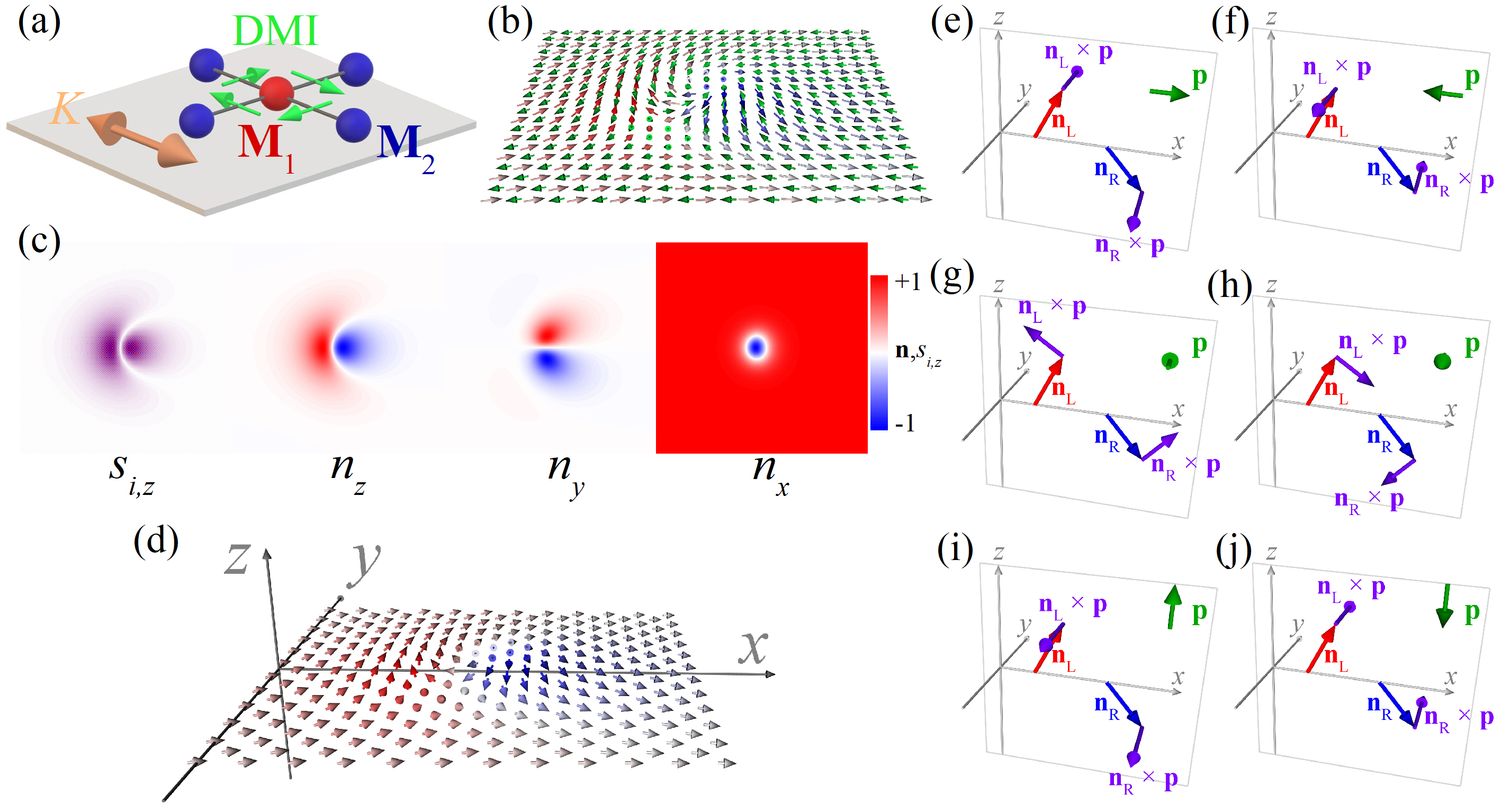
Proposal of nonreciprocal transport of FiM bimerons. We consider a FiM film with two sublattice magnetization and [Fig. 1(a)], and the interfacial Dzyaloshinskii-Moriya interaction (DMI) [38, 40] is introduced, which can be induced at the magnetic layer/heavy metal interface. To form FiM bimerons, the ferrimagnets with in-plane magnetic anisotropy (such as DyCo5 [58]) are promising materials. Here we focus on the study of a FiM film with in-plane easy-axis anisotropy, in which the asymmetrical bimeron is a stable solution, similar to the cases of FM [55] and AFM [30] bimerons. For the interfacial DMI shown in Fig. 1(a), it is usually responsible for stabilizing the skyrmion with rotational symmetry (the axis of rotation is parallel to the polar axis that is perpendicular to the - plane) [59]. For the FiM system we consider, the in-plane magnetic anisotropy forces the magnetization to tilt away from the polar axis, which violates the rotational symmetry dominated by DMI. As reported in Refs. [59, 27], in the tilted magnetic phases (the magnetization of a homogeneously magnetized state is tilted away from the polar axis), the rotationally symmetrical spin texture is an incompatible form and the asymmetrical spin textures appear. Figure 1(b) shows the spin structure of a FiM bimeron, and the components of its reduced magnetization and Néel vector are presented in the Fig. 1(c). The Néel vector in real space for a FiM bimeron is plotted in Fig. 1(d), showing that although the size of the left meron is different from that of the right meron, the bimeron’s spin structure still has mirror symmetry about the - plane.
Additionally, we derive a closed equation for the Néel vector [60, 61] (see Supplemental Material [62] for details), . and are the staggered and net spin densities, respectively [61]. , , , and are the saturation magnetization, gyromagnetic ratio, vacuum permeability constant, homogeneous exchange constant and damping constant, respectively. and relate to the effective field and current density, respectively (Supplemental Material [62]). In the above equation, only the damping-like spin torque is considered, while the field-like spin torque is not included. The effect of field-like spin torque on the FiM bimeron has been discussed in Supplemental Material [62]. The above equation indicates that the current-induced effective field relates to the cross product of the Néel vector and polarization vector . Such current-induced effective fields are of interest to us in the following symmetry analysis. As mentioned earlier, the bimeron’s spin structure is symmetric about the - plane, so that the Néel vector is canceled in the direction and the component of will not contribute to the nonreciprocal dynamics. Thus, we only need to pay attention to the components of in the - plane and their corresponding current-induced effective fields (). As shown in Figs. 1(e)-1(j), we sketch two vectors and to represent the --plane components of the Néel vector for two merons, respectively. Based on the symmetry consideration, and are symmetric about the axis for a bimeron with a symmetrical shape (see Fig. S1 of Supplemental Material [62]), while for the bimeron studied here it has an asymmetrical shape, resulting in the breaking of this symmetry. Figure 1(e) shows the results of for , where the cross product operation causes the current-induced effective fields to be perpendicular to the - plane. When we change the sign of the current, which is equivalent to changing the direction of , i.e., , the corresponding current-induced effective fields are still perpendicular to the - plane [Fig. 1(f)]. By comparing Fig. 1(e) with Fig. 1(f), we see that for and , the current-induced effective fields are symmetric about the - plane, so that the bimeron does not exhibit the nonreciprocal motion behavior. Similar mirror symmetry is observed for the case of [Figs. 1(i) and 1(j)], so there is no nonreciprocal phenomenon.
However, for [Fig. 1(g)] and [Fig. 1(h)], is in the - plane, and obviously is not mirror-symmetrical to , so that the opposite currents have different effects on the meron on the left in Fig. 1(d) [this result also applies to the meron on the right in Fig. 1(d)]. For a bimeron with a symmetrical shape, as mentioned above, and are symmetric about the axis, indicating that the effect of the positive current on the left meron (the right meron) is equivalent to that of the negative current on the right meron (the left meron). Therefore, although opposite currents have different effects on each meron, the structural symmetry causes the opposite currents to have the same effects on the whole, so that the bimeron with a symmetrical shape will not show nonreciprocal transport, which has been confirmed in Supplemental Material [62]. For the FiM bimeron studied in this work, it has an asymmetrical shape [Fig. 1(c)], resulting in the presence of nonreciprocal phenomena. Namely, nonreciprocal transport is attributed to the asymmetry of the bimeron structure.
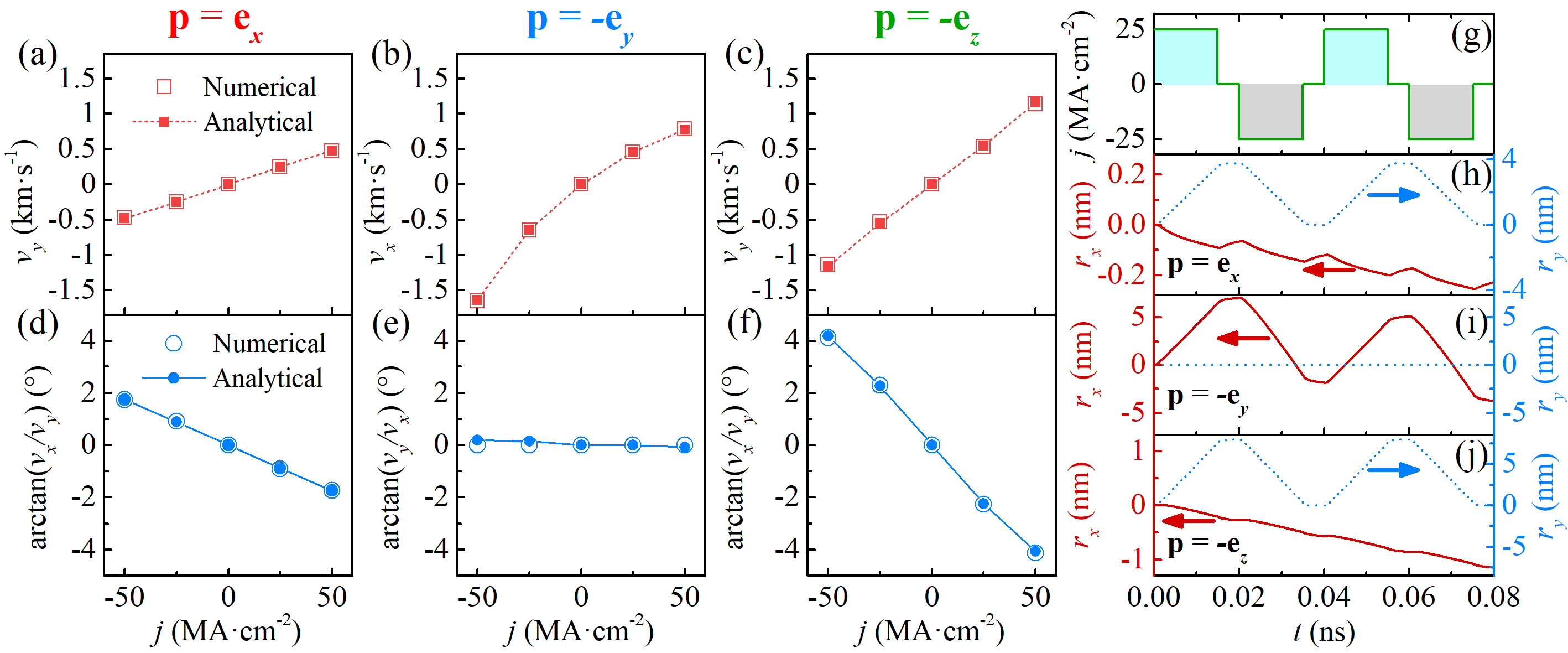
Current-induced nonreciprocal transport and drift motion of FiM bimerons. To verify the above analysis, we have simulated the magnetization dynamics of FiM bimerons and obtained the bimeron speeds, as shown in Figs. 2(a)-2(c). We indeed observe that only when the polarization vector is along the direction (perpendicular to the symmetry plane of the bimeron’s spin structure), the FiM bimeron driven by opposite currents has different speeds, that is, it exhibits the nonreciprocal transport [Fig. 2(b)]. As expected by the above symmetry analysis, for the cases where is along the or directions [Figs. 2(a) and 2(c)], such a nonreciprocal transport does not appear. Here we employ the LLG equation with the damping-like spin torque [63, 64] to simulate the dynamics of FiM bimerons, and the simulation details are given in Supplemental Material [62]. We also simulate the creation of FiM bimerons (see Figs. S4 and S5 of Supplemental Material [62]) and the creation process is given in Supplemental Movie 1-3. Moreover, based on the definition of the guiding center [65], we obtain the time evolution of and the bimeron velocity (see Fig. S8 of Supplemental Material [62]). is the topological charge [49, 22].
We now discuss the current-induced drift motion of FiM bimerons. Figures 2(a)-2(c) present the bimeron speeds in the desired motion direction (it is in , and directions for , and , respectively). The FiM bimeron at the angular momentum compensation point has an ability to move with a speed of about km s-1, similar to the AFM spin textures [28]. However, spin currents may induce a drift speed which is perpendicular to the desired motion direction, even if the FiM system is at the angular momentum compensation point (i.e., ). As shown in Figs. 2(d) and 2(f) where and respectively, the angle between the actual and desired motion directions is not zero, that is, the FiM bimeron shows a drift motion, and such an angle increases with the applied currents . For the case of , the drift motion can be safely disregarded [Fig. 2(e)].
To explain the simulation results, we derived the Thiele equation (see Supplemental Material [62] for details) [66, 61, 67, 68], from which we obtain the steady motion speeds,
| (1) |
where . and with the layer thickness . denotes the driving force induced by the damping-like spin torque (its expression is given in Supplemental Material [62]). If , Eq. (1) indicates that the bimeron speed is inversely proportional to the damping (see Fig. S9 of Supplemental Material [62]).
To verify the above analytical formula, we simulate the motion of FiM bimerons and calculate the bimeron velocities for different values of . Figure 3 shows the comparison of the numerical and analytical velocities, where the analytical velocities for all polarization vectors are in good agreement with the numerical results. Moreover, Fig. 3 shows that one of the velocity components (, ) is symmetric about , while the other component is antisymmetric. From Eq. (1), we see that one of the velocity components is proportional to with a constant , i.e., , while the other component , where because we fixed the values of and in the simulation. For it presents a symmetric curve, while for , an antisymmetric curve is obtained.
Assuming that the main driving force is in the direction () and the system is at the angular momentum compensation point (), from Eq. (1), the drift speed is obtained, . Note that (or ) is always nonzero for spin textures. According to the above formula of the drift speed, we find that there are two factors which cause the drift motion even if . The first factor is the presence of a nonzero [27] and the second factor is that an additional force perpendicular to the desired motion direction is induced by the applied currents. In order to verify the above analysis, we calculated the numerical values of and (Figs. S10 and S12 of Supplemental Material [62]), and then substituting them into Eq. (1) gives the analytical drift speeds which are consistent with the numerical results, as shown in Figs. 2(d)-2(f). Moreover, the numerical values of and confirm that the drift motion presented in Figs. 2(d) and 2(f) is due to the presence of a nonzero and an additional force [they originate from the deformation of the bimeron’s spin structure after the spin currents are applied (Fig. S13 of Supplemental Material [62])]. The drift speed due to the nonzero is greater than that due to the presence of an additional force for the case of Fig. 2(d), while the drift speed in Fig. 2(f) is dominated by the additional force.
Since FiM bimerons exhibit the nonreciprocal transport, an alternating current pulse presented in Fig. 2(g) induces the bimeron to show a ratchet motion [69, 70, 71, 72, 73] if we take [Fig. 2(i)]. Thus, FiM bimerons are ideal information carriers in AC racetrack storage devices [71]. For and , the bimeron does not show the nonreciprocal motion in the direction and the final value of is zero [Figs. 2(h) and 2(j)], while due to the presence of the drift motion [Figs. 2(d) and 2(f)], the final values of are not equal to zero.
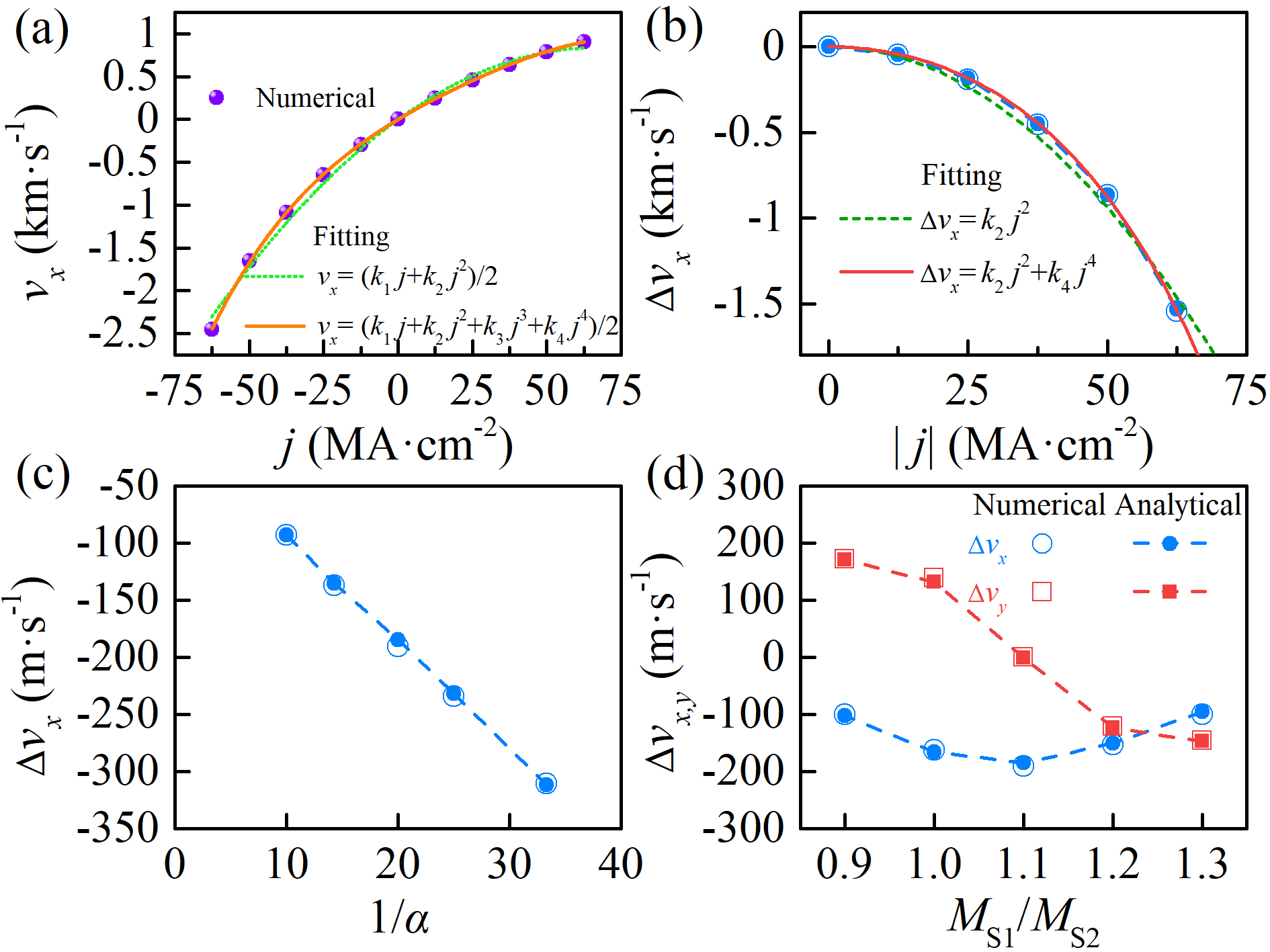
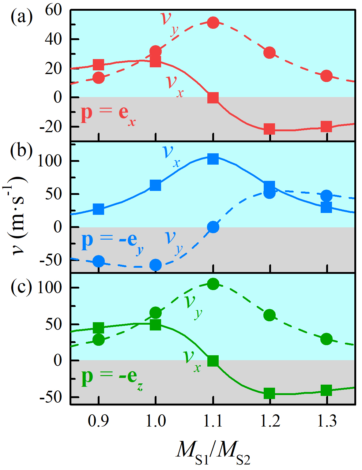
To quantify the nonreciprocal transport of FiM bimerons, the speed difference is defined. In Figs. 4(b)-4(d), is calculated as a function of the current density , the damping and the ratio of and . According to the fitting results shown in Fig. 4(b), the relationship between and is well described by this function , where we take and . To understand the results shown in Fig. 4(b), let us return to Eq. (1). For , Eq. (1) is simplified as , where and are related to the bimeron’s spin structure so their values are affected by the applied currents. As mentioned earlier, opposite currents have different effects on the FiM bimeron with an asymmetrical shape, so that the value of for a positive current is different from that for a negative current. Thus, the relation between and must include even terms in addition to odd terms, so the speed is written as a general polynomial form, with coefficient . Considering the first two terms of such a polynomial, the fitting results almost match the numerical simulations [Fig. 4(a)] (if more high-order terms are considered, the gap between the fitting results and numerical simulations will be narrowed). From the above speed , we obtain the speed difference that only contains even terms, (the magnitude of , and is directly related to the strength of nonreciprocal transport). In addition, taking different damping , is calculated and summarized in Fig. 4(c), showing that is inversely proportional to , as indicated by this equation . Moreover, by changing the value of , and for different are obtained, as shown in Fig. 4(d), where reaches its maximum value at the angular momentum compensation point (), and and almost are symmetric and antisymmetric about , respectively.
Generalization of nonreciprocal transport to magnetic skyrmions. In the above sections, we discussed the nonreciprocal transport of the FiM bimeron with a positive topological charge . Such a nonreciprocal transport is also observed for the FiM bimeron with a negative (see Fig. S17 of Supplemental Material [62]). The results of nonreciprocal transport of FiM bimerons can be extended to other types of spin textures with broken symmetry. For general topological solitons, e.g. skyrmions, they have a symmetrical structure so nonreciprocal transport does not appear, while the bimerons under investigation have intrinsic asymmetrical shape, resulting in the presence of nonreciprocal dynamics. Therefore, in order to attain the nonreciprocal transport, a break in structural symmetry of spin textures is required. As shown in Fig. S18 of Supplemental Material [62], when an in-plane magnetic field is utilized to break the rotational symmetry of a FM skyrmion, the skyrmion driven by opposite currents exhibits nonreciprocal transport. Compared to the intrinsic asymmetry of bimerons (, Fig. 4), this externally induced asymmetry of skyrmions gives rise to a weak nonreciprocity (, Fig. S18 of Supplemental Material [62]).
Conclusions. We have analytically and numerically studied the drift and nonreciprocal motions of FiM bimerons driven by spin currents. Our results demonstrate that due to the deformation of the bimeron’s spin structure, spin currents may induce a drift speed which is perpendicular to the desired motion direction, even if the FiM system is at the angular momentum compensation point. Moreover, the symmetry analysis shows that since the FiM bimeron studied here has an asymmetrical shape, the bimeron driven by opposite currents exhibits nonreciprocal transport. Our analysis of nonreciprocal transport of FiM bimerons is applicable to other types of spin textures with broken symmetry and our results are useful for building bimeron-based spintronic devices, such as bimeron diode and AC racetrack memory.
This study is supported by Guangdong Special Support Project (Grant No. 2019BT02X030), Shenzhen Fundamental Research Fund (Grant No. JCYJ20210324120213037), Shenzhen Peacock Group Plan (Grant No. KQTD20180413181702403), Pearl River Recruitment Program of Talents (Grant No. 2017GC010293) and National Natural Science Foundation of China (Grant Nos. 11974298 and 61961136006). J.X. acknowledges the support by the National Natural Science Foundation of China (Grant No. 12104327). X.Li acknowledges the support by the Guangdong Basic and Applied Basic Research Foundation (Grant No. 2019A1515111110). X.Z. was an International Research Fellow of Japan Society for the Promotion of Science (JSPS). X.Z. was supported by JSPS KAKENHI (Grant No. JP20F20363). O.A.T. acknowledges the support by the Australian Research Council (Grant No. DP200101027), the Cooperative Research Project Program at the Research Institute of Electrical Communication, Tohoku University (Japan), and by the NCMAS 2021 grant. Q.S. acknowledges funding support from the Shenzhen-Hong Kong-Macau Science and Technology Program (Category C, Grant No. SGDX2020110309460000), Research Grant Council-Early Career Scheme (Grant No. 26200520), and the Research Fund of Guangdong-Hong Kong-Macao Joint Laboratory for Intelligent Micro-Nano Optoelectronic Technology (Grant No. 2020B1212030010). G.Z. acknowledges the support by the National Natural Science Foundation of China (Grant Nos. 51771127, 51571126, and 51772004), the Scientific Research Fund of Sichuan Provincial Education Department (Grant Nos. 18TD0010 and 16CZ0006). X.Liu acknowledges the support by the Grants-in-Aid for Scientific Research from JSPS KAKENHI (Grant Nos. JP20F20363 and JP21H01364). M.E. acknowledges the support by the Grants-in-Aid for Scientific Research from JSPS KAKENHI (Grant Nos. JP17K05490 and JP18H03676) and the support by CREST, JST (Grant Nos. JPMJCR16F1 and JPMJCR20T2).
References
- [1] R. Takashima, Y. Shiomi, and Y. Motome, Phys. Rev. B 98, 020401(R) (2018).
- [2] Y. Tokura and N. Nagaosa, Nat. Commun. 9, 3740 (2018).
- [3] Y. Fan, Q. Shao, L. Pan, X. Che, Q. He, G. Yin, C. Zheng, G. Yu, T. Nie, M. R. Masir, A. H. MacDonald, and K. L. Wang, Nano Lett. 19, 692 (2019).
- [4] N. Li, J. Ren, L. Wang, G. Zhang, P. Hänggi, and B. Li, Rev. Mod. Phys. 84, 1045 (2012).
- [5] J. R. Whyte and J. M. Gregg, Nat. Commun. 6, 7361 (2015).
- [6] X. Xing, P. W. T. Pong, and Y. Zhou, J. Appl. Phys. 120, 203903 (2016).
- [7] L. Song, H. Yang, B. Liu, H. Meng, Y. Cao, and P. Yan, J. Magn. Magn. Mater. 532, 167975 (2021).
- [8] J. H. Franken, H. J. M. Swagten, and B. Koopmans, Nat. Nanotechnol. 7, 499 (2012).
- [9] T. Ideue, K. Hamamoto, S. Koshikawa, M. Ezawa, S. Shimizu, Y. Kaneko, Y. Tokura, N. Nagaosa, and Y. Iwasa, Nat. Phys. 13, 578 (2017).
- [10] S. Toyoda, N. Abe, S. Kimura, Y. H. Matsuda, T. Nomura, A. Ikeda, S. Takeyama, and T. Arima, Phys. Rev. Lett. 115, 267207 (2015).
- [11] S. Tateno and Y. Nozaki, Phys. Rev. Appl. 13, 034074 (2020).
- [12] U. K. Rößler, A. N. Bogdanov, and C. Pfleiderer, Nature 442, 797 (2006).
- [13] D.-H. Jung, H.-S. Han, N. Kim, G. Kim, S. Jeong, S. Lee, M. Kang, M.-Y. Im, and K.-S. Lee, Phys. Rev. B 104, L060408 (2021).
- [14] L. Zhao, X. Liang, J. Xia, G. Zhao, and Y. Zhou, Nanoscale 12, 9507 (2020).
- [15] H. Fook, W. Gan, and W. Lew, Sci. Rep. 6, 21099 (2016).
- [16] J. Wang, J. Xia, X. Zhang, X. Zheng, G. Li, L. Chen, Y. Zhou, J. Wu, H. Yin, R. Chantrell, and Y. Xu, Appl. Phys. Lett. 117, 202401 (2020).
- [17] S. S. Parkin, M. Hayashi, and L. Thomas, Science 320, 190 (2008).
- [18] O. Gomonay, T. Jungwirth, and J. Sinova, Phys. Rev. Lett. 117, 017202 (2016).
- [19] S. Mühlbauer, B. Binz, F. Jonietz, C. Pfleiderer, A. Rosch, A. Neubauer, R. Georgii, and P. Böni, Science 323, 915 (2009).
- [20] B. Göbel, I. Mertig, and O. A. Tretiakov, Phys. Rep. 895, 1 (2021).
- [21] M. Ezawa, Phys. Rev. B 83, 100408(R) (2011).
- [22] S. Z. Lin, A. Saxena, and C. D. Batista, Phys. Rev. B 91, 224407 (2015).
- [23] A. O. Leonov and I. Kézsmárki, Phys. Rev. B 96, 014423 (2017).
- [24] Y. A. Kharkov, O. P. Sushkov, and M. Mostovoy, Phys. Rev. Lett. 119, 207201 (2017).
- [25] X. Z. Yu, W. Koshibae, Y. Tokunaga, K. Shibata, Y. Taguchi, N. Nagaosa, and Y. Tokura, Nature 564, 95 (2018).
- [26] B. Göbel, A. Mook, J. Henk, I. Mertig, and O. A. Tretiakov, Phys. Rev. B 99, 060407(R) (2019).
- [27] R. Murooka, A. O. Leonov, K. Inoue, and J. Ohe, Sci. Rep. 10, 396 (2020).
- [28] L. Shen, J. Xia, X. Zhang, M. Ezawa, O. A. Tretiakov, X. Liu, G. Zhao, and Y. Zhou, Phys. Rev. Lett. 124, 037202 (2020).
- [29] X. Zhang, J. Xia, L. Shen, M. Ezawa, O. A. Tretiakov, G. Zhao, X. Liu, and Y. Zhou, Phys. Rev. B 101, 144435 (2020).
- [30] X. Li, L. Shen, Y. Bai, J. Wang, X. Zhang, J. Xia, M. Ezawa, O. A. Tretiakov, X. Xu, M. Mruczkiewicz, M. Krawczyk, Y. Xu, F. L. Evans, R. W. Chantrell, and Y. Zhou, npj Comput. Mater. 6, 169 (2020).
- [31] T. Nagase, Y.-G. So, H. Yasui, T. Ishida, H. K. Yoshida, Y. Tanaka, K. Saitoh, N. Ikarashi, Y. Kawaguchi, M. Kuwahara, and M. Nagao, Nat. Commun. 12, 3490 (2021).
- [32] S. Woo, K. M. Song, X. Zhang, Y. Zhou, M. Ezawa, X. Liu, S. Finizio, J. Raabe, N. J. Lee, S. I. Kim, S. Y. Park, Y. Kim, J. Y. Kim, D. Lee, O. Lee, J. W. Choi, B. C. Min, H. C. Koo, and J. Chang, Nat. Commun. 9, 959 (2018).
- [33] K.-J. Kim, S. K. Kim, Y. Hirata, S.-H. Oh, T. Tono, D.-H. Kim, T. Okuno, W. S. Ham, S. Kim , G. Go, Y. Tserkovnyak, A. Tsukamoto, T. Moriyama, K.-J. Lee, and T. Ono, Nat. Mater. 16, 1187 (2017).
- [34] L. Caretta, M. Mann, F. Büttner, K. Ueda, B. Pfau, C. M. Günther, P. Hessing, A. Churikova, C. Klose, M. Schneider, D. Engel, C. Marcus, D. Bono, K. Bagschik, S. Eisebitt, and G. S. D. Beach, Nat. Nanotechnol. 13, 1154 (2018).
- [35] T. Xu, Z. Chen, H.-A. Zhou, Z. Wang, Y. Dong, L. Aballe, M. Foerster, P. Gargiani, M. Valvidares, D. M. Bracher, T. Savchenko, A. Kleibert, R. Tomasello, G. Finocchio, S.-G. Je, M.-Y. Im, D. A. Muller, and W. Jiang, Phys. Rev. Mater. 5, 084406 (2021).
- [36] S. Gao, H. Diego Rosales, F. A. Gómez Albarracín, V. Tsurkan, G. Kaur, T. Fennell, P. Steffens, M. Boehm, P. Čermák, A. Schneidewind, E. Ressouche, D. C. Cabra, C. Rüegg, and O. Zaharko, Nature 586, 37 (2020).
- [37] H. Jani, J.-C. Lin, J. Chen, J. Harrison, F. Maccherozzi, J. Schad, S. Prakash, C.-B. Eom, A. Ariando, T. Venkatesan, and P. G. Radaelli, Nature 590, 74 (2021).
- [38] N. Nagaosa and Y. Tokura, Nat. Nanotechnol. 8, 899 (2013).
- [39] G. Finocchio, F. Büttner, R. Tomasello, M. Carpentieri, and M. Kläui, J. Phys. D: Appl. Phys. 49, 423001 (2016).
- [40] A. Fert, N. Reyren, and V. Cros, Nat. Rev. Mat. 2, 17031 (2017).
- [41] K. Everschor-Sitte, J. Masell, R. M. Reeve, and M. Kläui, J. Appl. Phys. 124, 240901 (2018).
- [42] Y. Zhou, Natl. Sci. Rev. 6, 210 (2019).
- [43] X. Zhang, Y. Zhou, K. M. Song, T.-E. Park, J. Xia, M. Ezawa, X. Liu, W. Zhao, G. Zhao, and S. Woo, J. Phys. Condens. Matter 32, 143001 (2020).
- [44] J. Sampaio, V. Cros, S. Rohart, A. Thiaville, and A. Fert, Nat. Nanotechnol. 8, 839 (2013).
- [45] W. Jiang, X. Zhang, G. Yu, W. Zhang, X. Wang, M. Benjamin Jungfleisch, John E. Pearson, X. Cheng, O. Heinonen, K. L. Wang, Y. Zhou, A. Hoffmann, and Suzanne G. E. te Velthuis, Nat. Phys. 13, 162 (2017).
- [46] K. Litzius, I. Lemesh, B. Krüger, P. Bassirian, L. Caretta, K. Richter, F. Büttner, K. Sato, O. A. Tretiakov, J. Förster, R. M. Reeve, M. Weigand, I. Bykova, H. Stoll, G. Schütz, G. S. D. Beach, and M. Kläui, Nat. Phys. 13, 170 (2017).
- [47] J. Zang, M. Mostovoy, J. H. Han, and N. Nagaosa, Phys. Rev. Lett. 107, 136804 (2011).
- [48] X. Zhang, Y. Zhou, and M. Ezawa, Sci. Rep. 6, 24795 (2016).
- [49] J. Barker and O. A. Tretiakov, Phys. Rev. Lett. 116, 147203 (2016).
- [50] M. N. Potkina, I. S. Lobanov, H. Jónsson, and V. M. Uzdin, J. Appl. Phys. 127, 213906 (2020).
- [51] Y. Hirata, D.-H. Kim, S. K. Kim, D.-K. Lee, S.-H. Oh, D.-Y. Kim, T. Nishimura, T. Okuno, Y. Futakawa, H. Yoshikawa, A. Tsukamoto, Y. Tserkovnyak, Y. Shiota, T. Moriyama, S.-B. Choe, K.-J. Lee, and T. Ono, Nat. Nanotechnol. 14, 232 (2019).
- [52] M. Augustin, S. Jenkins, R. F. L. Evans, K. S. Novoselov, and E. J. G. Santos, Nat. Commun. 12, 185 (2021).
- [53] X. Lu, R. Fei, L. Zhu, and L. Yang, Nat. Commun. 11, 4724 (2020).
- [54] W. Sun, W. Wang, H. Li, G. Zhang, D. Chen, J. Wang, and Z. Cheng, Nat. Commun. 11, 5930 (2020).
- [55] L. Shen, X. Li, J. Xia, L. Qiu, X. Zhang, O. A. Tretiakov, M. Ezawa, and Y. Zhou, Phys. Rev. B 102, 104427 (2020).
- [56] X. Zhang, J. Xia, M. Ezawa, O. A. Tretiakov, H. T. Diep, G. Zhao, X. Liu, and Y. Zhou, Appl. Phys. Lett. 118, 052411 (2021).
- [57] T. L. Gilbert, IEEE Trans. Magn. 40, 3443 (2004).
- [58] A. A. Ünal, S. Valencia, F. Radu, D. Marchenko, K. J. Merazzo, M. Vázquez, and J. Sánchez-Barriga, Phys. Rev. Appl. 5, 064007 (2016).
- [59] A. O. Leonov, T. L. Monchesky, J. C. Loudon, and A. N. Bogdanov, J. Phys. Condens. Matter 28, 35LT01 (2016).
- [60] K. M. D. Hals, Y. Tserkovnyak, and A. Brataas, Phys. Rev. Lett. 106, 107206 (2011).
- [61] S. K. Kim, K.-J. Lee, and Y. Tserkovnyak, Phys. Rev. B 95, 140404(R) (2017).
- [62] See Supplemental Material at http:// for the details of numerical simulations and analytical derivations for the FiM bimerons, which cites Refs. [57, 75, 76, 49, 55, 28, 30, 66, 77, 61, 44, 74].
- [63] J. C. Slonczewski, J. Magn. Magn. Mater. 159, L1 (1996).
- [64] R. Tomasello, E. Martinez, R. Zivieri, L. Torres, M. Carpentieri, and G. Finocchio, Sci. Rep. 4, 6784 (2014).
- [65] S. Komineas and N. Papanicolaou, Phys. Rev. B 92, 064412 (2015).
- [66] A. A. Thiele, Phys. Rev. Lett. 30, 230 (1973).
- [67] E. G. Tveten, A. Qaiumzadeh, O. A. Tretiakov, and A. Brataas, Phys. Rev. Lett. 110, 127208 (2013).
- [68] O. A. Tretiakov, D. Clarke, G. W. Chern, Y. B. Bazaliy, and O. Tchernyshyov, Phys. Rev. Lett. 100, 127204 (2008).
- [69] C. Reichhardt, C. J. O. Reichhardt, and M. V. Milošević, arXiv:2102.10464 (2021).
- [70] J. C. Bellizotti Souza, N. P. Vizarim, C. J. O. Reichhardt, C. Reichhardt, and P. A. Venegas, Phy. Rev. B 104, 054434 (2021).
- [71] B. Göbel and I. Mertig, Sci. Rep. 11, 3020 (2021).
- [72] X. Ma, C. J. Olson Reichhardt, and C. Reichhardt, Phys. Rev. B 95, 104401 (2017).
- [73] C. J. Olson Reichhardt and C. Reichhardt, Annu. Rev. Condens. Matter Phys. 8, 51 (2017).
- [74] Z. Chen, X. Zhang, Y. Zhou, and Q. Shao, arXiv:2112.04073 (2021).
- [75] S. Rohart and A. Thiaville, Phys. Rev. B 88, 184422 (2013).
- [76] E. G. Tveten, T. Müller, J. Linder, and A. Brataas, Phys. Rev. B 93, 104408 (2016).
- [77] V. Baltz, A. Manchon, M. Tsoi, T. Moriyama, T. Ono, and Y. Tserkovnyak, Rev. Mod. Phys. 90, 015005 (2018).