Spin to charge conversion at Rashba-split SrTiO3 interfaces from resonant tunneling.
Abstract
Spin-charge interconversion is a very active direction in spintronics. Yet, the complex behaviour of some of the most promising systems such as SrTiO3 (STO) interfaces is not fully understood. Here, on the basis of a 6-band method combined with spin-resolved scattering theory, we give a theoretical demonstration of transverse spin-charge interconversion physics in STO Rashba interfaces. Calculations involve injection of spin current from a ferromagnetic contact by resonant tunneling into the native Rashba-split resonant levels of the STO triangular quantum well. We compute an asymmetric tunneling electronic transmission yielding a transverse charge current flowing in plane, with a dependence with gate voltage in a very good agreement with existing experimental data.
I Introduction
The interconversion between spin and charge currents mediated by Rashba interactions [1], observed in a wide range of systems (Ag/Bi interfaces [2], SrTiO3 two-dimensional electron gases (STO 2DEGs) [3, 4, 5, 6, 7, 8] CoFeB/MgO [9], Fe/Ge, -Sn [2, 10]), offers huge technological opportunities from spin orbit torque and magnetic commutation to THz wave generation [11, 12, 13, 14, 15]. In Rashba systems, a flow of charge results in an out-of equilibrium spin density arising from the uncompensated spin-texture at the Fermi surfaces, the so-called Rashba-Edelstein effect (REE)[16, 17, 18]. Conversely, the inverse REE (IREE) allows for spin-charge conversion (SCC). Oxide interfaces based on SrTiO3 (STO) have attracted a specific attention owing to their substantial Rashba field. Several works [3, 4, 5, 19] have reported the observation of an enormous gate-tunable IREE in NiFe/LaAlO3(LAO)/STO, NiFe/AlOx(ALOx)/STO and related systems, with a SCC efficiency significantly larger than that of Ag/Bi(111) [2]. This makes STO 2DEGs promising candidates for the next-generation of high-speed and low-power spintronic devices such as magnetoelectric spin-orbit (MESO) transistors [20, 21, 22, 23].
However, the fundamentals and understanding SCC phenomena in 2DEGs oxide and heterostructures as provided in spin-pumping experiments is still in its infancy owing to the particular geometry measurements. In spin-pumping experiments performed on these systems [3, 5], a pure spin current is generated in a top magnetic contact of a tunnel devices, spin-current propagating in the confined STO layer constituting a quantum well (QW) before giving rise to spin-charge conversion via assisted spin-orbit interactions (SOI). This makes largely not suitable the application of a conventional theory and modelling based on the linear Kubo’s approach applied to the STO host matrix; unlike the issue of the reciprocal charge-to-spin conversion as required e. g. for the spin-torque problem.
In this article, we propose a modelling of SCC in the framework giving rise to equivalent IREE phenomena in a STO electron gas (2DEG) confined in an oxide triangular quantum well (TQW) considering the specific structure of a NiFe/LAO/STO magnetic tunnel junction. We expose new theoretical insights on these phenomena from a quantum resonant tunneling point of view taking into account the symmetry breaking properties of Kramer’s pair conjugates in STO QWs. We combine a method and a scattering approach to describe spin-orbit assisted transport and SCC [24, 25, 26, 27] and demonstrate the occurrence of a lateral charge current with a specific gate dependence in very good agreement with experiments. We explain recent experimental data [3, 5] and go beyond existing tight-binding (TB) models [28, 29, 5, 30] for tunnel structures, demonstrating the robustness of our method.
The paper is organized as follow. Section II focuses on the model description and the calculations of the electronic band structure of STO in the presence of a Rashba surface potential. We compare our modelling to recent tight-binding (TB) results involving also the orbital structure. Section III is devoted to the calcualtion details of the resonant tunneling through Rashba states within STO quantum wells (QWs) together with their dependence on the gate voltage or electric field along the confinement direction (direction normal to interfaces). Section IV introduces the asymmetry of the tunneling transmission and discusses the associated spin-charge conversion responsible for the transverse charge current.
II STO Band structure with Rashba interactions.
II.1 Modelling.
We start by describing the electronic band structure of the STO host material. TB [28, 29, 31, 32, 5, 30] as well as first principle theory [33] have been extensively used to model the Rashba properties of STO 2DEGs. Nevertheless, although TB may correctly describe the Rashba energy splitting, it does not explicity deal with tunnelling structures. In addition, theories of SCC in oxide systems were limited, up to now, to in-plane charge current [17, 18, 30] whereas the spin-pumping technique, used in STO [3, 5] as in semiconductor-based junctions [34], implies a tunneling current normal to the layers. To this end, we follow the approach of Heeringen et al. [35, 36, 37] and Ho [37]. One then considers the 6 following basis functions, namely the two spin-degenerated light (le) and heavy electrons (he), as well as the two split-off (so) components at the point (). Such characters (le, he, so) are defined here along the quantification direction, , normal to the layers. Note that they give rise to an opposite he and le character for the energy band dispersions in the QW plane directions as found for semiconductors, wherein and refer to bonding p-type symmetry orbitals in the latter case. The states ( the total angular momentum and its projection on the quantum axis) are then defined as:
where represents the tensorial product of the Ti 3d orbitals and the two spin states . The Hamiltonian is given via a set of cubic parameters namely , the spin orbit splitting and a possible tetragonal distortion energy splitting [35] according to to give in fine:
| (1) |
with , , , , , . In the basis set of the order: , the Hamiltonian (Eq. [1]) can be re-written as:
| (2) |
with . We chose eVÅ2, eVÅ2, eVÅ2, meV, meV, obtained from a fitting procedure to Density Functional Theory (DFT) [35, 37]. One may possibly add an additional Bychkov-Rashba extra-term in the SrTiO3 layer of the form: as proposed in Ref. [40] where is the Rashba parameter (the Rashba velocity is ), is unit vector along , is the momentum operator and the Pauli matrices, one obtains the different Fermi surfaces for both the majority and minority spin channels.
II.2 STO Band structure involving Rashba potentials.
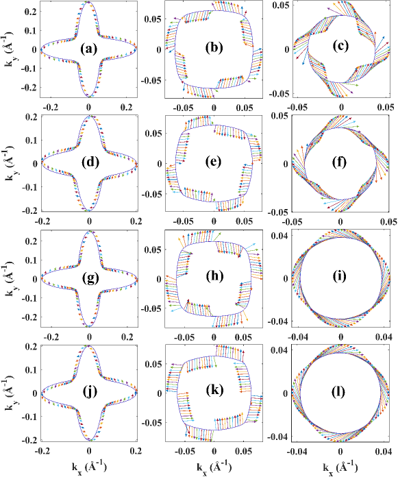
We now give a rapid description of the STO spin-resolved band structure in the presence of Rashba interactions where we fix now meV.Å. We compare our results to the ones of recent tight-binding (TB) treatment [30]. Without magnetism, the resulting electronic bands of STO subject to an additional Rashba interaction are displayed on Fig. 1. Such additional Rashba term introduced is equivalent, in spirit, to the had-hoc Rashba hopping surface term proposed in TB [28, 30]. The Fermi energy is chosen here to lie 0.04 eV above the bottom of the conduction band. The different bands and Fermi surfaces corresponds to respective (Fig. 1a, b and c) and spin channels (Fig. 1d, e and f), calculated from the above Hamiltonian. Figs. 1(a,d), Figs. 1(b,e) and Figs. 1(c,f) correspond respectively to he, le and so constituting the 6-band manifold. The heavy (he), light (le) and spin-orbit (so) character of the bands are considered along the direction parallel to the electronic wavevector considering that the majority he eigenvectors slightly mix with so and vice-versa. In agreement with the cubic symmetry, one observes that the spin vectors remains orthogonal to the and directions as well as normal to the corresponding to each square diagonals. An in-plane helical spin texture thus emerge due to Rashba interactions with opposite winding for the spin channels; and such spin texture may be associated to Rashba-Edelstein (REE) as well as inverse related effects. Figs. 1g-l give the corresponding orbital texture associated to the 3d-Ti orbitals showing the same type of helical structures. Note however that the correspondence between the spin and orbital textures for each band is not straightforward, between antiparallel (for the two first subbands) or parallel configurations (last subband). These results are in exact agreement with the TB calculations of Johansson et al. [30].
III Resonant tunnel theory with Rashba character.
III.1 Design of the tunneling structures.
We now turn to the properties of a FM/I/STO tunnel device where ’FM’ represent a 3d ferromagnetic contact as represented e.g by NiFe and ’I’ the oxide barrier (typically LAO or AlO). We have considered the same type Hamiltonian for NiFe, without tetragonal distortion nor Rashba terms, but considering meV for 3d elements and including an exchange splitting term with =0.1 eV and a magnetization oriented along the in-plane direction. That way, as known from the spin-dependent tunneling process, we are able to select one or two spin-channels in the tunneling process depending on the electron elastic energy.
Unlike the aforementioned calculations of the STO band structure II.2 involving an explicit Rashba term (), the peculiarity of our tunneling approach will be the appearance of equivalent features from the native triangular potential with , assumption that we will consider henceforth. We will also simplify the self-consistent potential in STO considering a triangular form of the confined potential [41, 42, 35, 36] ( is the charge), with the potential at the STO interface and the electric field in the range meV/Å [43]. Moreover, we have considered here the same cubic parameters for the barrier ’I’ of height eV. The reference for the energy is taken 50 meV below the Fermi energy of the FM metal and matches with the bottom of the majority spin band. According to Ref. [44] the band offset between the barrier and STO is eV at zero bias but may vary with a gate voltage due to the charge transfer and its influence onto the self-consistent induced potential. For the following, the width of the TQW is kept fixed to 6 nm leading to an electric field of meV/Å at .
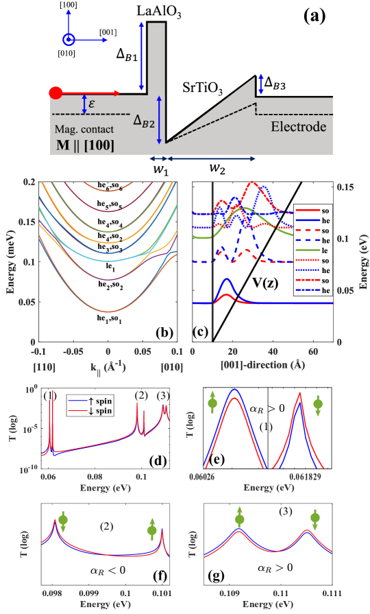
The structure under investigation is then sketched on Fig. 2a. The second barrier on the substrate side, and whose profile can be easily modified, is necessary for the formation of quantized states in the central STO layer and allows the collection of the current. Note however, that in the situation of spin-charge conversion induced by spin-pumping experiments as presently modelled, the collection of a longitudinal charge current in the STO substrate is not mandatory. Indeed, the spin-pumping current may be represented by a combined flux of majority spin to the right and equivalent minority spin flux to the left only causing, by transmission asymmetry effects, the transverse charge current in the plane of the quantum well we are searching for. This argument demonstrates the power of our present calculation method adapted to spin-pumping techniques.
III.2 Quantum mechanics and electronic transmission.
The wavefunction of the system that we have to solve is a solution of the Schrödinger equation:
| (3) |
that we have to solve without considering additional interface Rashba potential. At the vicinity of a given Rashba quantized level (or resonance ) at energy in the TQW, the band-selected transmission coefficient ( here is the band index and denotes explicitly the spin) are of the form [45]:
| (4) |
where and are respectively the spin-dependent energy broadening from the coupling to the FM and the unpolarized energy broadening towards the STO reservoir. is sensitive to the spin eigenvalue of (respectively parallel or antiparallel to ) whereas is not. will differ between the two split Rashba states for along in agreement with the symmetry rule required for the IEE process. generally larger depicts the electron lifetime out of the 2DEG into STO. The voltage-integrated tunneling current on a given resonant level is with the results that for and for . It results that the electronic transmission across a quantized Rashba state in STO and its hierarchy relative to their spin orientation may depends on the relative ratio so that, unlike conventional tunneling, a resonant transmission may invert the apparent sign of the Rashba interactions depending on the electron energy.
The calculation of the band-to-band selected transmission coefficients between incoming channel () and outgoing channel () (with )have been performed from the value of the band-selected transmission amplitudes by using the multiple scattering Green’s function formalism (evaluation of the S-scattering matrix computed from the scattering path operator). The discretization of the scattering region was performed into adjacent layers with . The transmission amplitude at each interfaces between two consecutive regions have been found by using the standard matching conditions of continuity of the wavefunction and wavecurrent [47] without considering any additional surface Rashba terms.
III.3 Results.
Fig. 2b displays the energy dispersion in the STO TQW plane obtained for the different subbands (he1, he2, le1, he3, he4,…) at along and . One observes the appearance of an energy splitting for the first three subbands (he1, he2, le1) relative to the two spins. This indicates a Rashba splitting without the use of any additional surface Rashba terms. Fig. 2c displays the quantized wavefunction for a strict normal incidence () for the first five levels and showing a strong hybridization between the he and so components; the le band remains pure. Indeed, a particular he-so mixture leads to a pure character of smaller mass near and able to minimize the quantization energy for the first two levels. The third level (le1) retains a pure character [30]. Generally, at a finite wave vector , each quantized state will be a mixture of he, le and so subbands leading to a nonparabolic dispersion, especially at the vicinity of the anticrossing Lifshitz point. Here, the Rashba spin splitting reaches its largest value where the cubic Rashba spin-orbit term dominates the linear contribution close to [37].
Fig. 2(d-g) displays the resonant transmission spectra vs. the elastic energy for at a slight oblique incidence 0.05Å-1. Fig. 2d shows the first three spin-split resonances respectively he1 at 0.06 eV, he2 at 0.1 eV and le1 at 0.11 eV. The analysis reveals some trends about the sign of the effective Rashba interactions in STO. Comparing the shape of the two peaks, either a given spin channel transmission peak (say the majority spin in blue) is broader/narrower than its opposite spin counterpart as on Fig. 2e (or Fig. 2f) or its amplitude is larger/smaller as on Fig. 2g. From to on Fig. 2d-g, the Rashba coupling changes sign twice, as exhibited by the transmission for spins: it is respectively positive for both he1 and le1 and negative for he2 with respective amplitudes 50 meV Å, 50 meV Å and -100 meV Å as expected [44].
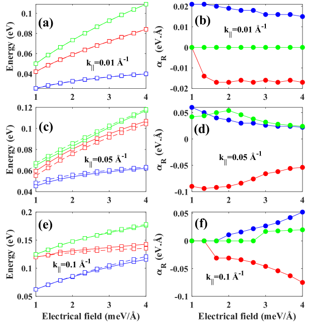
Action of a gate-voltage: We now focus on the action of a gate leading to a modulation of in STO. We model it by considering a change of the band offset between STO and the barrier with . Fig. 3 displays the resonance for the first three levels (he1, he2, le1) and different Å-1 (Fig. 3a), Å-1 (Fig. 3c), Å-1 (Fig. 3e) as a function of in the range between 1 and 4 meV/Å. For each and for most of the resonances, admits an almost power law dependence on except for the second level (=2) at Å-1 because of the band degeneracy close to the Lifchitz point. Such dependence of is very close to what is theoretically expected from the relationship with and the level for the given mass for he and le states. We have gathered on table 1 the values of the quantized energy extracted from our method and compared to the analytical theory given above with a good matching. On Fig. 3(b,d,f), the effective Rashba parameter vs. is plotted for different (0.01, 0.05, 0.1 Å-1) and for the different subbands he1 (blue), he2 (red) and le1 (green). At relative large Å-1 decreases largely on lowering down to 1 meV/Å-1 unlike at smaller . This has also been observed in the case of Schockley states [46].
| Quantized energy in the TQW (eV) | ||||
| quantized level | Å-1 ; F=1 meV/Å | Å-1 ; F=4 meV/Å | ||
| this work | theory | this work | theory | |
| he1 | 0.016 | 0.020 | 0.040 | 0.038 |
| he2 | 0.032 | 0.040 | 0.075 | 0.085 |
| le1 | 0.050 | 0.050 | 0.120 | 0.120 |
IV Spin to charge conversion from resonant transmission asymmetry.
We now turn to the calculation of the transmission coefficient in a FM/I/STO magnetic tunnel junctions. The calculation of the electronic transmission was performed in the 2D reciprocal space as a function of the in-plane wavevector . Hereafter, we will consecutively switch-off and switch-on the exchange term in the left ’FM’ magnetic contact and will compare the result of a non-magnetic (as played by Au or Al) and magnetic tunnel injector responsible for the appearance of a transverse charge current. We will consider different electric fields and 5 meV/Å; and in order to fit with the current values of , the band offset band offset was respectively set to of 10, 40, 130, 190 and 250 meV with fixed at 50 meV.
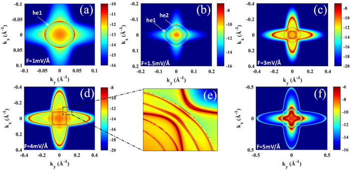
The results obtained for a non-magnetic contact () are displayed Figs. 4(a-f) showing the resonance transmission at each Rashba quantized levels in agreement with our previous modelling. In each case, one may observe that the transmission map obey a perfect cubic symmetry shape for electrons tunneling in the Brillouin zone as expected from the structure lattice structure (C4 symmetry). For meV/Å (Fig. 4a), tunneling involves a single he1 spin-split Rashba resonance and giving rise to the same transmission at equivalent points on the cubic Fermi surface. For meV/Å (Fig. 4b), tunneling involves two Rashba resonance he1 and he2 Rashba-split bands. For meV/Å(Fig. 4c), tunneling involves 6 different Rashba-split resonances, respectively he1, he2, 1e1, he3, he4-so and he5-so. When is further increased to meV/Å, other resonances appear (Figs. 4d,f) but always fulfilling a cubic symmetry shape and thus providing an exact compensation of lateral charge current in the QW plane. Such symmetry in the transmission coefficient between two opposite incidences, , is expected from the time inversion operator and Kramer’s pair conjugation in the STO TQW. Each spin state of in-plane incidence and energy is conjugated to a corresponding spin state of in-plane incidence and same energy . For a non magnetic system, an equivalent spin injection from the contact, it results an equal transmission vs. .
We now switch on the exchange parameter eV. The result is different due to the lift of the spin degeneracy of the Kramers’s pair within the TQW in the electronic transmission [48]. We calculate the corresponding transmission map as the same time that the transverse charge current for meV/Å. A magnetic contact allows an asymmetry of the transmission as a function of the carrier incidence with respect to the reflection plane defined by the magnetization and the surface normal. Due to the axial character of , two electrons with exact opposite in-plane wave vector may have different transmission amplitude [24, 25, 26, 27] unlike the case of non-magnetic systems. A charge current flowing in-plane is then expected to occur along the direction. The results are displayed on Fig. 5 respectively for meV/Å (Fig. 5a: point ), meV/Å (Fig. 5b: point ) and meV/Å (Fig. 5c: point ). The potential profiles vs. still match with an elastic resonant tunneling injection into ) the first he1 Rashba split bands ( with Å-1), into ) the two first he1 () and he2 () bands ( Å-1) with opposite sign of Rashba and into ) the he1 ( Å-1), he2 ( Å-1), le1 ( Å-1), he-so3 and he-so4 bands.
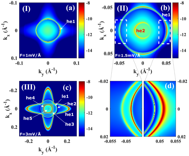
One observes now that, involving non-zero magnetism in the injector ( eV), the transmission does not obey a perfect cubic symmetry shape but differs for in the direction as expected (see e.g Fig. 5d). The transmission along remains symmetric for fixed . Concomitantly to a tunneling spin-current along , a different transmission along and has to be associated with a transverse charge flow along describing an IREE. In the case the transmission is larger along for the first he1 band which defines . For the case , the inner Rashba band with smaller gives an opposite sign to the transmission asymmetry and this should be linked to as previously mentioned. Note that in this tunneling geometry, the inner Rashba band gives an overall larger conduction owing to the reduced incidence (smaller ) and then to an overall negative IRE effect. In the case , the first Rashba band gives a standard Fermi ’cigar’ shape to the resonant transmission however assigned to a very small selected asymmetry. In the case , additional Rashba split band at higher energy (le1, he3-so, he4-so) of a positive Rashba signature yields an overall positive IRE (). These conclusions are compatible with the description of Fig. 3 in particular in terms of the Rashba coupling sign. Such transmission difference vs. is characterized by the asymmetry parameter as:
| (5) |
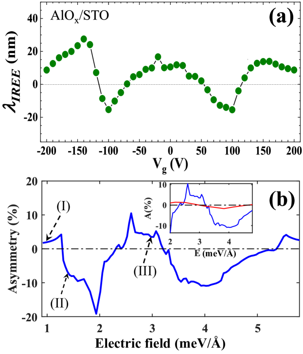
Chirality effects of the same origin have been discussed in terms of tunneling anomalous Hall effects or TAHE in semiconductors [38, 27] or in superconducting materials [39]. In this paper, we generalize these phenomena to resonant tunneling in oxide based systems. A non zero gives rise to a transverse charge current flowing in the QW plane with where is the QW width, the spin current along , as computed by our method and the spin-current injection angle from . Note however that is proportional to the spin-current polarization injected from the contact, and then proportional to the spin-density (or spin accumulation ) injected in the STO TQW. This gives the connection we are searching for between the transverse charge current and the spin-polarization in the STO, equivalent to IREE. In the present case, calculations give an an out-of-equilibrium spin-polarization in the STO QW textcolorred(not shown) with the chosen parameters. Whereas the charge current remains constant within the tunneling structure, , of vectorial nature, may vary in the STO TQW owing to the Rashba field inducing a local spin-precession (the Rashba interaction does not commute with the spin operator). Fig. 6b displays vs. for an electron beam incoming with incident energy (kinetic energy = 50 meV) from the band bottom. Upon the increase of above 1 meV/Å , starts with small positive value of about corresponding to a weak Rashba splitting of the first quantized level ( in Fig. 5a). Then, decreases down to a large negative due to an opposite spin textures of the second level for meV/Å. In this region, the asymmetry reaches a maximum absolute value of () at the largest Rashba splitting at the vicinity of the Lifshitz point where the current spin-polarization within the TQW approaches unity. Then, when is further increased, changes its sign to become positive again () when the third and upper levels get involved in the tunneling. This evolution of perfectly reproduces in shape the trend of spin to charge conversion length, , vs. bias reported in experiments of Vaz et al. [5] for ALO/STO (Fig. 6a). Fig. 6b gives the variation of when the right tunnel barrier is reduced to a minimum value meV making the energy broadening to the right reservoir very large and the outward tunneling time very short. The strong reduction of observed should be assigned to the reduction of the particle lifetime limiting thus the efficiency of the SCC in agreement with the standard diffusive model of IREE [2] in the regime of current-in-plane (CIP) injection.
V Conclusions.
Via a 6 band spin-dependent resonant tunneling model, we have demonstrated the gate dependence of the spin-charge interconversion mechanism in an insulator/STO triangular quantum well for perpendicular spin-current flow, in very good agreement with spin pumping experimental data. This is demonstrated without the need to add a supplementary interface Rashba potential. This behavior of tunneling asymmetry in LAO/STO system also demonstrates the universal phenomenon of chirality-driven skew scattering [27] involving strong electric fields or potential gradients and subsequent spin-orbit interactions. A deeper analysis will be required within this formalism to go beyond for further conclusions in fundamentals of SCC with STO. In particular, exploring the role of the orbital Edelstein effect, predicted to be strong in STO 2DEGs [30], and the influence of ferroelectricity [23], appear as interesting directions for the future.
Acknowledgements.
This work received support from the ERC Advanced Grant n° 833973 ’Fresco’. We acknowledge financial support from the Horizon 2020 Framework Programme of the European Commission under FET-Open Grant No. 863155 (s-Nebula). We acknowledge the ANR program ’ORION’ through grant number ANR-20-CE30-0022-01.References
- [1] Y. A. Bychkov and E. I. Rashba, Properties of a 2D Electron Gas with Lifted Spectral Degeneracy, JETP Letters 39, 78-83, (1984).
- [2] J. Sánchez, L. Vila, G. Desfonds, et al., Spin-to-charge conversion using Rashba coupling at the interface between non-magnetic materials, Nat Commun 4, 2944, (2013).
- [3] E. Lesne, Y. Fu, S. Oyarzun, et al., Highly efficient and tunable spin-to-charge conversion through Rashba coupling at oxide interfaces, Nature Mater 15, 1261–1266, (2016).
- [4] J.-Y. Chauleau, M. Boselli, S. Gariglio, R. Weil, G. de Loubens, J. M. Triscone, and M. Viret, Efficient spin-to-charge conversion in the 2D electron liquid at the LAO/STO interface, EPL 116, 17006, (2016).
- [5] D. C. Vaz, P. Noel, A. Johansson, et al., Mapping spin–charge conversion to the band structure in a topological oxide two-dimensional electron gas, Nat. Mater. 18, 1187–1193, (2019).
- [6] F. Trier, D. C. Vaz, P. Bruneel, P. Noel, et al., Electric-Field Control of Spin Current Generation and Detection in Ferromagnet-Free SrTiO3-Based Nanodevices, Nano Lett. 20, 1, 395–401, (2020).
- [7] D. C. Vaz, F. Trier, A. Dyrda l, A. Johansson et al., Determining the Rashba parameter from the bilinear magnetoresistance response in a two-dimensional electron gas, Phys. Rev. Mat. 4, 071001(R), (2020).
- [8] F. Trier, P. Noel, J.-V. Kim, J.-P. Attané, L. Vila, and M. Bibes, arXiv:2103.16271 [cond-mat.mtrl-sci] (2021).
- [9] O. Rousseau, C. Gorini, F. Ibrahim, J.-Y. Chauleau et al., Spin charge conversion in Rashba split ferromagnetic interfaces, arXiv:2103.16867 [condmat.mes-hall], (2021).
- [10] Han, W., Otani, Y. Maekawa, S., Quantum materials for spin and charge conversion, npj Quant Mater 3, 27 (2018).
- [11] Seifert, T., Jaiswal, S., Martens, U. et al., Efficient metallic spintronic emitters of ultrabroadband terahertz radiation, Nature Photon 10, 483–488 (2016).
- [12] M. B. Jungfleisch, Q. Zhang, W. Zhang, J. E. Pearson, R. D. Schaller, H. Wen, and A. Hoffmann, Control of Terahertz Emission by Ultrafast Spin-Charge Current Conversion at Rashba Interfaces, Phys. Rev. Lett. 120, 207207, (2018).
- [13] C. Zhou, Y. P. Liu, Z. Wang, S. J. Ma et al., Broadband Terahertz Generation via the Interface Inverse Rashba-Edelstein Effect, Phys. Rev. Lett. 121, 086801 (2018).
- [14] I. F. Akyildiz, A. Kak, and S. Nie, 6G and Beyond: The Future of Wireless Communications Systems, IEEE Access 8, 133995 (2020).
- [15] T. H. Dang, J. Hawecker, E. Rongione, G. Baez Flores et al., Ultrafast spin-currents and charge conversion at 3d-5d interfaces probed by time-domain terahertz spectroscopy, Applied Physics Review 7, 041409 (2020).
- [16] V. Edelstein, Spin polarization of conduction electrons induced by electric current in two-dimensional asymmetric electron systems, Solid State Communications 73, 233 (1990).
- [17] K. Shen, G. Vignale, and R. Raimondi, Microscopic Theory of the Inverse Edelstein Effect, Phys. Rev. Lett. 112, 096601 (2014).
- [18] C. Gorini, A. Maleki Sheikhabadi, K. Shen, I. V. Tokatly, G. Vignale, and R. Raimondi, Theory of current-induced spin polarization in an electron gas, Phys. Rev. B95, 205424 (2017).
- [19] L. M. Vicente-Arche, S. Mallik, M. Cosset-Cheneau, P Noel et al., Metal/SrTiO3 two-dimensional electron gases for spin-to-charge conversion, arXiv:2102.03093 [cond-mat.mes-hall] (2021).
- [20] Y.-Y. Pai, A. Tylan-Tyler, P. Irvin, and J. Levy, Physics of SrTiO3-based heterostructures and nanostructures: a review, Reports on Progress in Physics 81, 036503 (2018).
- [21] S. Ohya, D. Araki, L. Duc Anh, S. Kaneta, M. Seki, H. Tabata, and M. Tanaka, Efficient intrinsic spin-to-charge current conversion in an all-epitaxial single-crystal perovskite-oxide heterostructure of La0.67Sr0.33MnO3/LaAlO3/SrTiO3, Phys. Rev. Research 2, 012014(R) (2020).
- [22] S. Manipatruni, D. E. Nikonov, C. C. Lin et al., Scalable energy-efficient magnetoelectric spin–orbit logic, Nature 565, 35–42 (2019).
- [23] P. Noel, F. Trier, L. M. V. Arche, J. Brehin et al., Non-volatile electric control of spin–charge conversion in a SrTiO3 Rashba system, Nature 580, 483-486 (2020).
- [24] T. H. Dang, H. Jaffrès, T. L. Hoai Nguyen, and H.-J. Drouhin, Giant forward-scattering asymmetry and anomalous tunnel Hall effect at spin-orbit-split and exchange-split interfaces, Phys. Rev. B92, 060403(R) (2015).
- [25] T. H. Dang, D. Q. To, E. Erina, T. H. Nguyen, V. Safarov, H. Jaffrès, and H.-J. Drouhin, Theory of the anomalous tunnel hall effect at ferromagnet-semiconductor junctions, Journal of Magnetism and Magnetic Materials 459, 37 (2018).
- [26] D. Q. To, T.-H. Dang, H. Nguyen, V. Safarov, J.-M. George, H.-J. Drouhin, and H. Jaffrès, Spin-Orbit Currents, Spin-Transfer Torque and Anomalous Tunneling in III–V Heterostructures Probed by Advanced 30- and 40-Bands Tunneling Methods, IEEE Transactions on Magnetics 55, 1 (2019).
- [27] I. V. Rozhansky, D. Q. To, H. Jaffrès, and H.-J. Drouhin, Chirality-induced tunneling asymmetry at a semiconductor interface, Phys. Rev. B102, 045428 (2020).
- [28] Z. Zhong, A. Toth, and K. Held, Theory of spin-orbit coupling at LaAlO3/SrTiO3 interfaces and SrTiO3 surfaces, Phys. Rev. B87, 161102(R) (2013).
- [29] G. Khalsa, B. Lee, and A. H. MacDonald, Theory of t2g electron-gas Rashba interactions, Phys. Rev. B88, 041302(R) (2013).
- [30] A. Johansson, B. Gobel, J. Henk, M. Bibes, and I. Mertig, Spin and orbital Edelstein effects in a two-dimensional electron gas: Theory and application to SrTiO3 interfaces, Phys. Rev. Research 3, 013275 (2021).
- [31] K. V. Shanavas and S. Satpathy, Electric Field Tuning of the Rashba Effect in the Polar Perovskite Structures, Phys. Rev. Lett. 112, 086802 (2014).
- [32] G. Seibold, S. Caprara, M. Grilli, and R. Raimondi, Theory of the Spin Galvanic Effect at Oxide Interfaces, Phys. Rev. Lett. 119, 256801 (2017).
- [33] W. Kong, T. Yang, J. Zhou, Y. Z. Luo et al., Tunable Rashba spin-orbit coupling and its interplay with multiorbital effect and magnetic ordering at oxide interfaces, arXiv:2101.07586 [cond-mat.mtrl-sci] (2021).
- [34] C. Cerqueira, J. Y. Qin, H. Dang, A. Djeffal et al., Evidence of Pure Spin-Current Generated by Spin Pumping in Interface-Localized States in Hybrid Metal–Silicon–Metal Vertical Structures, Nano Lett. 19, 90 (2019).
- [35] L. W. van Heeringen, G. A. de Wijs, A. McCollam, J. C. Maan, and A. Fasolino, k.p subband structure of the LaAlO3/SrTiO3 interface, Phys. Rev. B88, 205140 (2013).
- [36] L. W. van Heeringen, A. McCollam, G. A. de Wijs, and A. Fasolino, Theoretical models of Rashba spin splitting in asymmetric SrTiO3-based heterostructures, Phys. Rev. B95, 155134 (2017).
- [37] C. S. Ho, W. Kong, M. Yang, A. Rusydi, and M. B. Jalil, Tunable spin and orbital polarization in SrTiO3-based heterostructures, New Journal of Physics 21, 103016 (2019).
- [38] A. Matos-Abiague, and J. Fabian, Tunneling Anomalous and Spin Hall Effects, Phys. Rev. Lett. 115, 056602 (2015).
- [39] A. Costa, A. Matos-Abiague, and J. Fabian, Skew Andreev reflection in ferromagnet/superconductor junctions, Phys. Rev. B100, 060507(R) (2019).
- [40] L. Petersen and P. Hedegard, A simple tight-binding model of spin–orbit splitting of sp-derived surface states, Surface Science 459, 49 (2000).
- [41] O. Copie, V. Garcia, C. Bodelfeld, C. Carretero et al., Towards Two-Dimensional Metallic Behavior at LaAlO3/SrTiO3 Interfaces, Phys. Rev. Lett. 102, 216804 (2009).
- [42] A. Santander-Syro, O. Copie, T. Kondo et al., Two-dimensional electron gas with universal subbands at the surface of SrTiO3, Nature 469, 189–193 (2011).
- [43] J. Biscaras, S. Hurand, C. Feuillet-Palma et al., Limit of the electrostatic doping in two-dimensional electron gases of LaXO3(X = Al, Ti)/SrTiO3, Sci Rep 4, 6788 (2014).
- [44] P. King, S. McKeown Walker, A. Tamai et al., Quasiparticle dynamics and spin–orbital texture of the SrTiO3 two-dimensional electron gas., Nat Commun 5, 3414 (2014).
- [45] E. Y. Tsymbal, A. Sokolov, I. F. Sabirianov, and B. Doudin, Resonant Inversion of Tunneling Magnetoresistance, Phys. Rev. Lett. 90, 186602 (2003).
- [46] H. Ishida, Rashba spin splitting of Shockley surface states on semi-infinite crystals, Phys. Rev. B90, 235422 (2014).
- [47] D. L. Smith and C. Mailhiot, Theory of semiconductor superlattice electronic structure, Rev. Mod. Phys. 62, 173 (1990).
- [48] G. Goldoni, and A. Fasolino, spin splitting in asymmetric double quantum wells: a mechanism for spin-dependent hole delocalization, Phys. Rev. Lett. 70, 2051, (1993).