RFormer: Transformer-based Generative
Adversarial Network for Real Fundus Image
Restoration on A New Clinical Benchmark
Abstract
Ophthalmologists have used fundus images to screen and diagnose eye diseases. However, different equipments and ophthalmologists pose large variations to the quality of fundus images. Low-quality (LQ) degraded fundus images easily lead to uncertainty in clinical screening and generally increase the risk of misdiagnosis. Thus, real fundus image restoration is worth studying. Unfortunately, real clinical benchmark has not been explored for this task so far. In this paper, we investigate the real clinical fundus image restoration problem. Firstly, We establish a clinical dataset, Real Fundus (RF), including 120 low- and high-quality (HQ) image pairs. Then we propose a novel Transformer-based Generative Adversarial Network (RFormer) to restore the real degradation of clinical fundus images. The key component in our network is the Window-based Self-Attention Block (WSAB) which captures non-local self-similarity and long-range dependencies. To produce more visually pleasant results, a Transformer-based discriminator is introduced. Extensive experiments on our clinical benchmark show that the proposed RFormer significantly outperforms the state-of-the-art (SOTA) methods. In addition, experiments of downstream tasks such as vessel segmentation and optic disc/cup detection demonstrate that our proposed RFormer benefits clinical fundus image analysis and applications. The dataset, code, and models will be made publicly available at https://github.com/dengzhuo-AI/Real-Fundus.
Real Fundus Image Restoration, Transformer, Generative Adversarial Network, Self-Attention
1 introduction
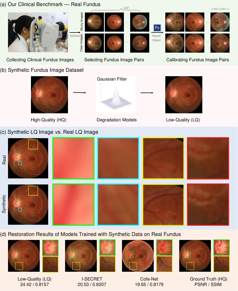
Due to the safety and cost-effectiveness in acquiring, fundus images are widely used by ophthalmologists for early eye disease detection and diagnosis, including glaucoma [3, 4, 5], diabetic retinopathy [6, 7, 8], cataract [9, 10], and age-related macular degeneration [11, 12]. However, different equipments and ophthalmologists pose large variations to the quality of fundus images. A screening study of 5,575 patients found that about of fundus images are of inadequate quality to be readable by ophthalmologists [13]. We analyze the factors causing the degradation in real fundus image capturing. Firstly, patients, especially infant patients, do not cooperate with the capturing process of fundus images. Specifically, most patients are reluctant to undergo pupil dilation, which causes poorly lit and blurred fundus images. Besides, infant patients usually can not resist the eye-closing reflex caused by a bright light during flash photography. Secondly, in practice, spatial pixel misalignment, color, and brightness mismatch are inevitable due to the changes in light conditions and misoperations of inexpert ophthalmologists. Thirdly, high-quality (HQ) fundus images can be collected in hospitals of developed areas using high-precision fundus cameras. However, these equipments are expensive and unaffordable for hospitals in some remote areas of under-developed or developing countries. As a result, low-precision and portable fundus cameras are used to capture low-quality (LQ) fundus images. These LQ fundus images easily mislead the clinical diagnosis and lead to unsatisfactory results of downstream tasks like blood vessels segmentation. Various biomarkers of the retina (, hemorrhage, microaneurysm, exudate, optic nerve and optic cup) are essential in different diseases. Therefore, it is necessary to ensure the prominence and visibility of each marker for precise clinical diagnosis. Thus, when LQ fundus images are captured in clinical diagnosis, ophthalmologists often repeat dozens of shots until HQ fundus images are obtained. Nonetheless, this repeated capturing process harms patients, degrades hospital efficiency, prevents reliable diagnosis of ophthalmologists, and impacts automated image analysis systems.
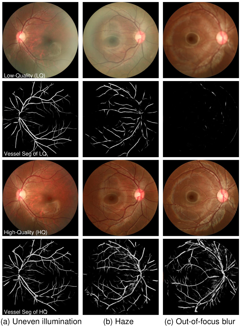
We observe the clinical fundus images and find that the main degradation types of LQ images include out-of-focus blur, motion blur, artifact, over-exposure, and over-darkness. Compared with other types of degradation, blur, especially out-of-focus blur, poses the most severe threat to image analysis and clinical diagnosis. An example is shown in Fig. 2, where the uneven illumination, haze, and out-of-focus blur degradation are presented in (a), (b), and (c), respectively. It can be observed that the performance of blood vessel segmentation only collapses on out-of-focus blurred fundus images.
Traditional fundus image restoration methods [14, 15] are mainly based on handcrafted priors. However, these model-based methods achieve unsatisfactory performance and generality due to the poor representing capacity. Recently, deep Convolutional Neural Networks (CNNs) have been widely used in natural image restoration and enhancement [16, 17, 18], e.g., super resolution [19, 20, 21, 22, 23, 24, 25], deraining [26], deblurring [27, 28, 29, 30, 31], enlighten [32, 33], etc. Inspired by the success of natural image restoration, CNNs have also been applied to fundus image restoration [34, 23, 22, 2, 1, 35, 36, 37, 38, 39]. Although impressive results have been achieved, CNN-based methods show limitations in capturing long-range dependencies. In recent years, the natural language processing (NLP) model, Transformer [40] has been introduced into computer vision and outperformed CNN-based methods in many tasks. The Multi-head Self-Attention (MSA) in Transformer excels at modeling non-local similarity and long-range dependencies. This advantage of Transformer may provide a possibility to address the limitations of CNN-based methods.
Existing deep learning methods rely on a large amount of LQ and HQ fundus image pairs. Unfortunately, real clinical benchmark has not been explored for fundus image reconstruction. There remains a data-hungry problem. As shown in Fig. 1 (b), to get more image pairs, artificially designed degradation models such as Gaussian filter are used to synthesize degraded fundus images from their high-quality counterparts. However, as depicted in Fig. 1 (c), artificial degradation is fundamentally different from clinical degradation. As shown in Fig. 1 (d), the two CNN-based methods [1, 2] trained with synthesized data fail in real fundus image restoration.
In this paper, we investigate the real fundus image restoration problem, which has not been studied in the literature. Our work is the first attempt. To begin with, we establish a clinical benchmark, Real Fundus (RF), including 120 LQ and HQ real clinical fundus image pairs to alleviate the data-hungry issue. Based on this dataset, we propose a novel method, namely Transformer-based Generative Adversarial Network (RFormer), for real fundus image restoration. Specifically, the generator and discriminator are built up by the basic unit, Window-based Self-Attention Blocks (WSABs). The self-attention mechanism equipped with each basic block excels at capturing the non-local self-similarity and long-range dependencies, which are the main limitations of existing CNN-based methods. In particular, the generator adopts a U-shape structure to aggregate multi-resolution contextual information. Unlike previous CNN-based Generative Adversarial Networks (GANs), we adopt a Transformer-based discriminator to extract non-local image prior information and thus improve the ability of discriminator to distinguish restored fundus images from the ground-truth HQ fundus images. Our Transformer-based adversarial training scheme encourages the generator to create more plausible-looking natural and visually-pleasant images with more detailed contents and structural textures.
Our contributions can be summarized as follows:
-
•
We establish a new clinical benchmark, RF, to evaluate algorithms in real fundus image restoration. To the best of our knowledge, this is the first real fundus image dataset.
-
•
We propose a novel Transformer-based method, RFormer, for real fundus image restoration. To the best of our knowledge, it is the first attempt to explore the potential of Transformer for this task in the literature.
-
•
Comprehensive quantitative and qualitative experiments demonstrate that our RFormer significantly outperforms SOTA algorithms. Extensive experiments of downstream tasks further validate the effectiveness of our method.
2 related work
2.1 Fundus Image Restoration
Traditional fundus image restoration and enhancement methods [14, 15] are mainly based on hand-crafted priors. For example, Setiawan [41] apply contrast limited adaptive histogram equalization (CLAHE) to fundus image enhancement. Some methods [42, 43, 44] decompose the reflection and illumination, achieving image enhancement and correction by estimating the solution in an alternate minimization scheme. However, these model-based methods achieve unsatisfactory performance and generality due to the poor representing capacity. With the development of deep learning, fundus image restoration has witnessed a significant progress. CNNs [34, 23, 22, 2, 1, 35, 36, 37, 38, 39] apply a powerful learning model to restore LQ fundus images. For instance, Zhao [23] propose an end-to-end deep CNN to remove the lesions on the fundus images of cataract patients. However, the cataract lesions are not caused by clinical fundus imaging. Sourya [22] , Shen [2], and Raj [39] customize different synthetic degradation models to better simulate the degradation types in actual clinical practice. However, real fundus image degradation is more sophisticated than synthesized degradation. It is hard to simulate real degradation by artificial degradation models completely. Thus, models trained on synthesized data easily fail in real fundus image restoration. In addition, the CNN-based methods show limitations in capturing non-local self-similarity and long-rang dependencies, which are critical for fundus image reconstruction.
2.2 Generative Adversarial Network
Generative Adversarial Network (GAN) is firstly introduced in [45] and has been proven successful in image synthesis [16, 17, 18], and translation [17, 18]. Subsequently, GAN is applied to image restoration and enhancement, e.g., super resolution [19, 20, 21, 22, 23, 24, 25], deraining [26], deblurring [27], enlighten [32, 33], dehazing [46, 47], image inpainting [48, 49], style transfer [18, 50], image editing [51, 52], medical image enhancement [53, 54, 23, 22], and mobile photo enhancement [55, 56]. Although GAN is widely applied in low-level vision tasks, few works are dedicated to improving the underlying framework of GAN, such as replacing the traditional CNN framework with Transformer. Jiang [57] propose the first Transformer-based GAN, TransGAN, for image generation. Nonetheless, to the best of our knowledge, the Transformer-based GAN has not been involved in fundus image restoration.
2.3 Vision Transformer
Transformer is proposed by [40] for machine translation. Recently, Transformer has achieved great success in high-level vision, such as image classification [58, 59, 60, 61, 62], semantic segmentation [63, 61, 62, 64], human pose estimation [65, 66, 67, 68, 69, 70], object detection [71, 72, 61, 73, 74], Due to the advantage of capturing long-range dependencies and excellent performance in many high-level vision tasks, Transformer has also been introduced into low-level vision [75, 76, 77, 78, 79, 80, 81]. SwinIR [78] uses Swin Transformer [61] blocks to build up a residual network and achieve SOTA results in natural image restoration. Chen [77] propose a large model IPT pre-trained on large-scale datasets with a multitask learning scheme. MST [82] presents a spectral-wise Transformer for HSI reconstruction. Although Transformer has achieved impressive results in many tasks, its potential in fundus image restoration remains under-explored.
3 Methodology
3.1 RFormer Architecture
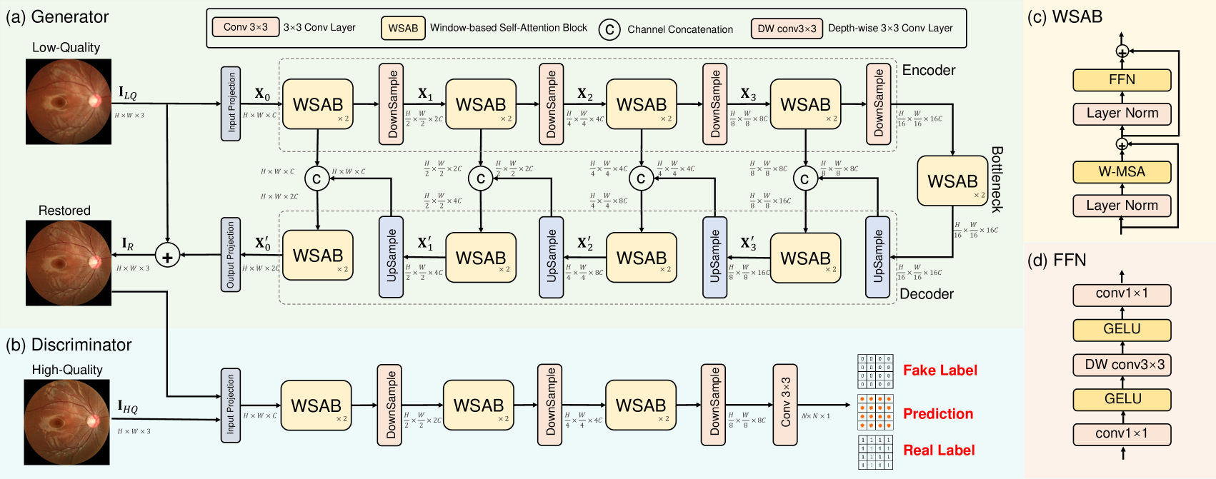
The architecture of RFormer is shown in Fig. 3, where (a) and (b) depict the generator and discriminator. Fig. 3 (c) illustrates the proposed Window-based Self-Attention Blocks (WSABs), which consists of a Feed-Forward Network (FFN) (detailed in Fig. 3 (d)), a Window-based Multi-head Self-Attention (W-MSA), and two layer normalization.
The generator adopts a U-shaped [83] architecture including an encoder, a bottleneck, and a decoder. The input LQ image is denoted as . Firstly, the generator exploits a projection layer consisting of a convolution (conv) and LeakyReLU to extract shallow feature . Secondly, encoder stages are used for deep feature extraction on . Each stage is composed of two consecutive WSABs and one downsampling layer. We adopt a conv with stride 2 as the downsampling layer to downscale the spatial size of feature maps and double the channel dimension. Thus, the feature of the -th stage in the encoder is denoted as . Here, indicates the four stages. Thirdly, undergoes the bottleneck that consists of two WSABs. Subsequently, following the spirits of U-Net, we customize a symmetrical decoder, which also contains stages. Each stage of the decoder is also composed of two WSABs and one upsampling layer. Similarly, the feature maps of the -th stage in the decoder is denoted as . The upsampling layer is a bilinear interpolation followed by a 33 conv layer. To alleviate the information loss caused by downsampling in the encoder, skip connections are used for feature fusion between the encoder and decoder. Finally, after undergoing the decoder, the feature maps pass through a 33 conv layer to generate a residual image . The restored fundus image can be obtained by .
As shown in Fig. 3 (b), the discriminator aims to distinguish the restored fundus images from ground-truth high-quality fundus images. As analyzed in [17], patch-level GAN is more effective than image-level GAN in capturing high-resolution and fine-grained image information, which is critical for restoring clinical fundus image restoration. Hence, we follow the adversarial training scheme based on image patches as PatchGAN and further propose a Transformer-based discriminator. More specifically, the discriminator employs the same architecture as the encoder in the generator followed by a 33 conv layer. The restored fundus image concatenated with the ground-truth HQ fundus image undergoes our proposed Transformer-based discriminator to generate the predicted map .
3.2 Window-based Self-Attention Block
The emergence of Transformer provides an alternative to address the limitations of CNN-based methods in modeling non-local self-similarity and long-range dependencies. However, as analyzed in Swin Transformer [61], the computational cost of the standard global Transformer is quadratic to the spatial size of the input feature (). This burden is nontrivial and sometimes unaffordable. To tackle this problem, we adopt the Window-based Multi-head Self-Attention (W-MSA) [61] as the self-attention mechanism and integrate it with the basic Transformer unit. The computational complexity of W-MSA is linear to the spatial size, which is much cheaper than that of standard global MSA. Inspired by Swin Transformer [61], we add window shift operations(WSO) in our proposed Window-based Multi-head Self-Attention Block (WSAB) to introduce cross-window connections. The components of our proposed WSAB are shown in Fig. 3 (c). WSAB consists of a W-MSA, an FFN, and two layer normalization. The details of FFN are shown in Fig. 3 (d). Then WSAB can be formulated as
| (1) | ||||
where represents the input feature maps of a WSAB. represents the layer normalization. and denote the output feature of W-MSA and FFN respectively.
3.2.1 Window-based Multi-head Self-Attention
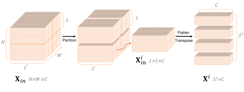
Instead of using global correspondence, we partition the feature map into non-overlapping windows. Subsequently, the token interactions are calculated inside each window. As shown in Fig. 4, given the input feature map with and being the height and the width. We partition into non-overlapping windows. The feature of the -th window is denoted as , where and . is flattened and transposed into . We conduct MSA on . Firstly, is linearly projected into query , key , and value :
| (2) |
where are learnable parameters, denoting the projection matrices of the query, key and value. We respectively split , and into heads along the channel dimension: , and . The dimension of each head is . The Self-Attention (SA) for head is formulated as
| (3) |
where and respectively represent the query, key and value of head respectively. The output tokens of the -th window can be obtained by
| (4) |
where Concat denotes the concatenating operation, represents the position embedding, and are learnable parameters. We reshape to obtain the output window feature map Finally, we merge all the patch representations to obtain the output feature maps .
3.2.2 Feed-Forward Network
As depicted in Fig. 3 (d), the Feed-Forward Network (FFN) consists of a layer with a GELU activation, a depth-wise layer with a GELU activation, and another layer.
3.3 Loss Functions
During the training procedure, we exploit the weighted sum of four loss functions as the overall training objective. They are described and analyzed in the following part.
3.3.1 Charbonnier Loss
The first loss function is the Charbonnier loss between the restored and ground-truth HQ images:
| (5) |
where denotes the restored fundus image, represents the ground-truth HQ fundus image, and denotes a constant which is empirically set to for all the experiments.
3.3.2 Fundus Quality Perception Loss
Unlike natural images, fundus images have specific acquisition process and anatomical structures. This indicates fundus images have highly similar styles. Therefore, we exploit high-level feature constraints to improve the perceptual quality and encourage the network to capture the fundus anatomical structures and styles. To this end, we propose Fundus Quality Perception Loss (FQPLoss). More specifically, we adopt VGG-19 [84] as the perception network and pre-train it on the fundus image quality evaluation dataset, Eye-Q [85] with the fundus image quality classification task. The Eye-Q dataset has 28,792 fundus images with three-level quality grading. The perception network trained on the Eye-Q dataset is capable of extracting the difference of high-level features between different qualities of fundus images. Subsequently, our FQPLoss can be formulated as
| (6) |
where and denote the height and width of the fundus image. denotes the feature extraction function of the pre-trained perception network. Our FQPLoss is customized to assess a solution with respect to perceptually relevant characteristics. By minimizing the FQPLoss , the model is encouraged to capture more high-level discriminative features and generate more visually-pleasant results.
3.3.3 Adversarial Loss
Our proposed Transformer-based discriminator aims to distinguish the restored fundus images from ground-truth HQ fundus images. More specifically, the discriminator outputs a patch score map , where and denote the height and width. The score of each position indicates how realistic the corresponding fundus image patch is. Then the adversarial loss is formulated as
| (7) | ||||
where denotes the mapping function of our proposed Transformer-based discriminator. trains the generator to fool the discriminator by generating more realistic restored fundus images. In contrast, encourages the discriminator to distinguish the restored images from real images.
3.3.4 Edge Loss
To enhance the high-frequency edge details, we exploit the edge loss function that focuses on the gradient information of images and enhances edge textures. To be specific, the edge loss function is formulated as
| (8) |
where represents the Laplacian operator.
3.3.5 The Overall Loss Function
Finally, the overall training objective is the weighted sum of the above four loss functions:
| (9) |
where are three hyper-parameters controlling the importance balance of different loss functions. Our proposed RFormer is end-to-end trained by minimizing . The weights of the perception network are fixed. Each mini-batch training procedure can be divided into two steps: (i) Fix the discriminator and train the generator. (ii) Fix the generator and train the discriminator. This adversarial training scheme encourages the reconstructed fundus images to be more photo-realistic and closer to the real clinical HQ fundus image manifold.
4 Real Fundus
This section introduces our clinical benchmark, Real Fundus (RF). It consists of 120 LQ and HQ clinical fundus image pairs with the spatial size of . The training and testing subsets are split in proportional to 3:1. Since blur significantly impacts clinical diagnosis and automated image analyzing systems, it is set to the primary degradation type of LQ fundus images. Besides, there are other degradation types such as artifacts and uneven illumination which are inevitably introduced in the fundus image capturing process.
4.1 Data Collecting Process
The collection process of our RF obtains the exemption determination from Shenzhen Eye Hospital and contains three steps: capturing, selecting, and calibrating fundus images.
4.1.1 Capturing
Instead of exploiting artificial degradation models (e.g., Gaussian Filter.) to synthesize LQ fundus images as shown in Fig. 1 (b), we directly use the degraded fundus images from the fail cases in practical capturing. As depicted in Fig. 1 (a), the fundus images are captured by ophthalmologists using a ZEISS VISUCAM200 fundus camera, which is a mainstream product of fundus camera. The price of ZEISS VISUCAM200 fundus camera is about 350,000 RMB. We select clinical fundus images from patients of different ages and different fundus states (e.g., leopard fundus, hemorrhage, microaneurysms, and drusen ) to expand the scope of our RF.
4.1.2 Selecting
When LQ fundus images are captured in practice, the operator will repeat capturing until HQ fundus images are obtained. Subsequently, we manually select LQ and HQ fundus image pairs of the same eye. To ensure the diversity of RF and avoid similar data, only one image pair is selected with one eye. Note that only HQ clear fundus images captured by experienced ophthalmologists can be used as the ground truths of degraded LQ images. Based on these strict criteria, we finally select 120 LQ and HQ fundus image pairs from the eye hospital database containing more than 30,00 eye instances. Each instance contains multiple fundus images.
4.1.3 Calibrating
After selecting fundus image pairs, we observe two issues in raw unprocessed fundus data. Firstly, the LQ and HQ fundus images are spatially misaligned (as illustrated in Fig. 1(a)). Secondly, there is a large black area around the eyeball. This black area is uninformative and may easily degrade the performance of the restoration model during the training procedure. Thus, to improve the quality of our RF, we calibrate the collected dataset using the software, Photoshop. Specifically, we first spatially align the image pairs and then cut off the black area around the eyeball.
4.2 Comparisons with Synthetic Dataset
4.2.1 LQ Fundus Images
We compare the LQ images from our RF and synthetic dataset in Fig. 1 (c). As can be seen from the zoom-in patches that the artificially synthesized degradation is fundamentally different from the real clinical degradation.
4.2.2 Domain Discrepancy
To validate the huge domain discrepancy between the synthetic and real clinical datasets, we adopt two CNN-based fundus image restoration methods, I-SECRET [1] and Cofe-Net [2], to conduct ablation study. We train them with the synthetic data and then test them on our RF. As shown in Fig. 1 (d), the two models fail to reconstruct the real clinical LQ fundus images. They either yield over-smooth results sacrificing detailed contents, or introduce visually unpleasant artifacts. Since the synthetic data can not be applied to real fundus image restoration, it still remains a severe data-hungry issue. To meet with this research requirement, we establish a large scale clinical dataset, RF. To the best of our knowledge, this is the first work contributing a real clinical fundus image restoration benchmark.
5 Experiments
5.1 Implementation Details
During the training procedure, fundus images are first cropped into the patches with the size of 128128. Then the patches are fed into our proposed RFormer. The Adam [89] optimizer (=0.9, =0.999) is adopted. The initial learning rate is set to . The cosine annealing strategy [90] is employed to steadily decrease the learning rate from the initial value to during the training procedure. Our RFormer is implemented by PyTorch. It takes about 12h using an NVIDIA RTX 3090 GPU to train for 100 epochs. The mini-batch size is set to 4. Random flipping and rotation are used for data augmentation. In the testing phase, the input is the whole image with the size of 25602560 for fair comparison with other methods. We adopt peak signal-to-noise ratio (PSNR) and structural similarity (SSIM) [91] as the metrics to evaluate the fundus image reconstruction performance.
| Method | PSNR | SSIM | Params(M) | FLOPS(G) |
| Cofe-Net [2] | 17.26 | 0.789 | 39.31 | 22.48 |
| GLCAE [87] | 21.37 | 0.570 | – | – |
| I-SECRET [1] | 24.57 | 0.854 | 10.85 | 14.21 |
| Bicubic+RL [86] | 25.34 | 0.824 | – | – |
| ESRGAN [20] | 26.73 | 0.823 | 15.95 | 18.41 |
| RealSR [88] | 27.99 | 0.850 | 15.92 | 29.42 |
| MST [82] | 28.13 | 0.854 | 3.48 | 3.59 |
| RFormer (Ours) | 28.32 | 0.873 | 21.11 | 11.36 |
| 5-Fold Cross-valid | 28.15 | 0.848 | 21.11 | 11.36 |
| 10-Fold Cross-valid | 28.38 | 0.863 | 21.11 | 11.36 |
| WSO | PSNR | SSIM | |||
|---|---|---|---|---|---|
| ✓ | ✓ | 27.42 | 0.840 | ||
| ✓ | ✓ | ✓ | 27.90 | 0.860 | |
| ✓ | ✓ | ✓ | 28.20 | 0.866 | |
| ✓ | ✓ | ✓ | 28.04 | 0.858 | |
| ✓ | ✓ | ✓ | 27.25 | 0.744 | |
| ✓ | ✓ | ✓ | ✓ | 28.32 | 0.873 |
5.2 Comparisons with State-of-the-Art Methods
We provide quantitative comparisons between our RFormer with seven SOTA methods including two model-based methods (GLCAE [87] and Bicubic+RL [86]), four CNN-based methods (RealSR [88], ESRGAN [20], I-SECRET [1], and Cofe-Net [2]), and one Transformer-based method (MST [82]). The quantitative comparisons on our RF are shown in Table 1, the proposed RFormer outperforms other competitors in terms of PSNR and SSIM. Specifically, RFormer achieves 0.33 and 1.59 dB improvement in PSNR when compared to RealSR [88] and ESRGAN [20].
| Discriminator | PatchGAN | PixelGAN | Pixel and Patch | Ours |
|---|---|---|---|---|
| PSNR | 27.52 | 28.00 | 27.70 | 28.32 |
| SSIM | 0.822 | 0.790 | 0.839 | 0.873 |
To verify the robustness of our RFormer, we conduct 5-fold and 10-fold cross-validation. The results are shown in Table 1. As can be seen that our Rformer still achieves robust results, e.g., 28.15 dB in 5-fold cross-validation and 28.38 dB in 10-fold cross-validation. The small gap in performance suggests that the overfitting is moderate while the effectiveness of RFormer is reliable and promising.
| Patch Size | 40 40 | ||||
|---|---|---|---|---|---|
| PSNR | 28.23 | 28.32 | 28.12 | 28.02 | 28.03 |
| SSIM | 0.866 | 0.873 | 0.827 | 0.862 | 0.796 |
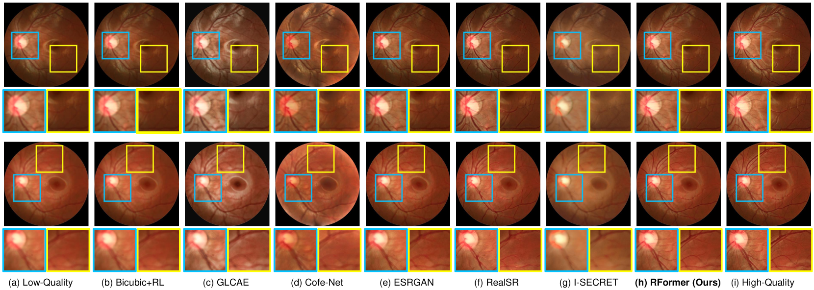
Fig. 5 depicts the qualitative comparisons on RF. It can be observed that Bicubic+RL [86], GLCAE [87], I-SECRET [1], and Cofe-Net [2] yield over-smooth results and fail to restore the LQ blurry fundus images. Although ESRGAN [20] and RealSR [88] can reconstruct more high-frequency edge details, they do not maintain the authenticity and anatomical structure of the original fundus. Some undesired artifacts are introduced to the restored images, which may severely mislead the clinical diagnosis. In contrast, our RFormer is capable of restoring more fine-grained contents and structural details without introducing artifacts. Thus, the fundus anatomical structure can be well preserved.
5.3 Ablation Study
5.3.1 FQPLoss
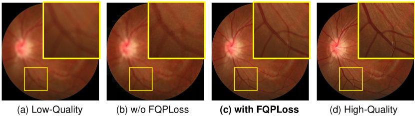
We adopt RFormer as the restoration model to conduct an ablation study to validate the effect of our FQPLoss. As listed in Table 2, when the FQPLoss is applied, the PSNR and SSIM are increased by 1.07 dB and 0.129, respectively. In addition, we provide visual comparisons in Fig. 7. As depicted in Fig. 7 (b), the model yields an over-smooth fundus image and fails in reconstructing the fine-grained vessel details without FQPLoss. As shown in Fig. 7 (c), when using our FQPLoss, the model restores more detailed anatomical structure contents and high-frequency textures.
5.3.2 Discriminator
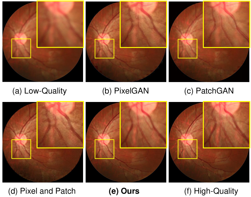
We conduct ablation study to compare our proposed Transformer-based discriminator with Traditional CNN-based discriminators. Please note that the Transformer-based generator remains unchanged. The results are reported in Table 3. Compared with the discriminators in CNN-based PatchGAN [17], PixelGAN [17], our Transformer-based discriminator yields the best performance. We provide qualitative comparisons in Fig. 6. It can be observed that our Transformer-based discriminator significantly outperforms CNN-based discriminators in terms of recovering detailed contents and preserving the anatomical structure consistency.
5.3.3 Patch Size
We experimentally analyze the effect of the patch size set in the Transformer-based discriminator. The results are shown in Table 4. Our RFormer achieves the best restoration result with the patch size of 4040.
5.3.4 Window Size
We change the window size of W-MSA and conduct experiments to study its effect. The results are reported in Table 6. It can be observed that our RFormer yields the best result when the window size is set to 88.
| Window Size | PSNR | SSIM | Params(M) | FLOPS(G) |
|---|---|---|---|---|
| w/o WSAB | 14.27 | 0.601 | 34.53 | 16.38 |
| 28.23 | 0.873 | 20.67 | 10.83 | |
| 8 8 | 28.32 | 0.873 | 21.11 | 11.36 |
| 27.82 | 0.819 | 27.54 | 13.46 | |
| 27.63 | 0.812 | 47.21 | 18.59 |
5.3.5 Window Shift Operations
We conduct ablation study to analyze the effect of the window shift operations. The results are reported in Table 2. The results indicate that the window shift operations can build cross-window connections and improve the performance of RFormer.
5.4 Clinical Image Analysis and Applications
The ultimate goal of restoring and enhancing fundus images is to serve the real clinical tasks better and improve the accuracy of clinical diagnosis. To validate the effectiveness of our proposed RFormer, we use it as a pre-processing technique for downstream clinical image analysis tasks, including vessel segmentation and optic disc/cup detection. LadderNet [92] and M-Net [93] are employed as the segmentation baselines.
5.4.1 User Study
Since the restored fundus images should meet the requirements of ophthalmologists, we adopt 30 LQ fundus images for user study. We use different image restoration methods to enhance these LQ images. Subsequently, we display these results in random order and ask the experienced ophthalmologists to score the quality of the restored images based on their extensive clinical experience. The score ranges from 0 to 100, larger values are better. The suppression of artifacts and preservation of lesions are taken into account. Finally, we collect responses from five ophthalmologists. The score results for each method are shown in Table.5. Our RFormer receives the highest score for best restored results.
5.4.2 Vessel Segmentation
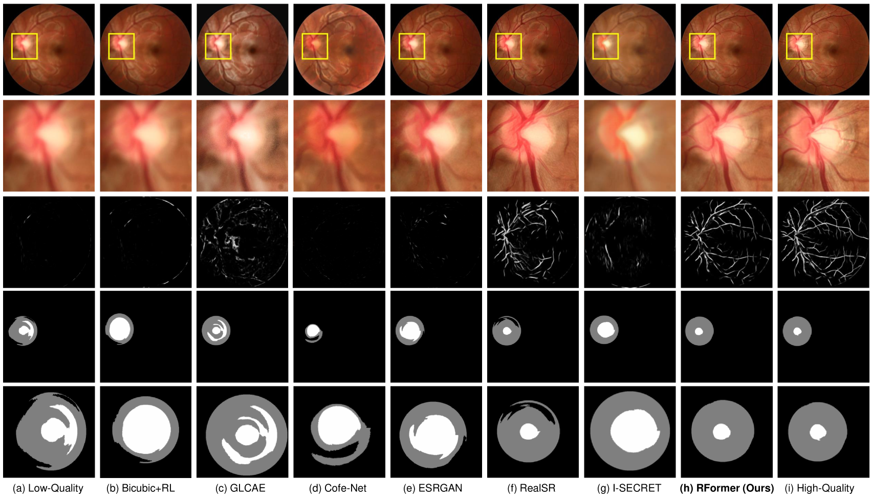
We test LadderNet [92] pre-trained on DRIVE [94] dataset for vessel segmentation on our collected RF. Please note that the vessel segmentation maps of real HQ fundus images serve as the references for comparison due to the lack of segmentation labels on our RF. The vessel segmentation results are shown in the third row of Fig.8. As can be seen that LadderNet fails in segmenting the blood vessels of clinical LQ fundus images. In contrast, LadderNet extracts obvious vessel structure of the fundus images restored by our RFormer, which is closest to the segmentation results of real HQ fundus images. These results clearly suggest the effectiveness of our proposed method.
5.4.3 Optic Disc/Cup Detection
We also evaluate the effect of our RFormer for the downstream disc/cup detection task. We test M-Net [93] pre-trained on ORIGA [95] dataset for optic disc/cup detection on our collected RF. Similar to the vessel segmentation task, the optic disc/cup detection results of real HQ fundus images function as the references due to the lack of segmentation labels. The qualitative comparisons of different fundus image restoration methods are depicted in Fig. 8. The fourth line is the optic disc/cup detection map and the fifth line depicts the zoom-in patches of the fourth line. It can be observed that M-Net fails to detect the disc/cup on clinical LQ fundus images. On the contrary, M-Net detects the optic cup and disc more accurately on the fundus images reconstructed by our RFormer. This evidence verifies that our method benefits the optic disc/cup detection task.
5.5 Fail Cases
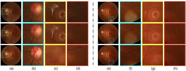
Although RFormer achieves good performance, it may not work in some scenes. Fig. 9 shows some fail cases of RFormer on our RF dataset. In the (a) and (e) column, from top to bottom are LQ fundus image, restored fundus image, and HQ fundus image. (b), (c), and (d) are three zoom-in patches of (a). (f), (g), and (h) are three zoom-in patches of (e). It can be clearly observed from 9 (c), (f), and (g) that our RFormer fails to remove the bright spots. As can be seen from 9 (b), (d), and (h) that our RFormer fails in enhancing the low-lights regions. It is difficult for RFormer to learn the feature in areas with insufficient contrast and brightness. We will continue to improve our work according to these fail cases.
6 Conclusion
In this paper, we establish the first real clinical fundus image restoration benchmark, Real Fundus, which contains LQ and HQ fundus image pairs to alleviate the data-hungry issue. Our dataset can help better evaluate restoration algorithms in clinical scenes. Based on this dataset, we propose a novel Transformer-based method, RFormer, for clinical fundus image restoration. To the best of our knowledge, it is the first attempt to explore the potential of Transformer in this task. Comprehensive qualitative and quantitative results demonstrate that our RFormer significantly outperforms a series of SOTA methods. Extensive experiments verify that the proposed RFormer serving as a data pre-processing technique can boost the performance of different downstream tasks, such as vessel segmentation and optic disc/cup detection. We hope this work can serve as a baseline for real clinical fundus image restoration and benefit the community of medical imaging.
References
- [1] P. Cheng, L. Lin, Y. Huang, J. Lyu, and X. Tang, “I-secret: Importance-guided fundus image enhancement via semi-supervised contrastive constraining,” in International Conference on Medical Image Computing and Computer-Assisted Intervention. Springer, 2021, pp. 87–96.
- [2] Z. Shen, H. Fu, J. Shen, and L. Shao, “Modeling and enhancing low-quality retinal fundus images,” IEEE Transactions on Medical Imaging, vol. 40, no. 3, pp. 996–1006, 2020.
- [3] X. Chen, Y. Xu, D. W. K. Wong, T. Y. Wong, and J. Liu, “Glaucoma detection based on deep convolutional neural network,” in 2015 37th annual international conference of the IEEE engineering in medicine and biology society (EMBC). IEEE, 2015, pp. 715–718.
- [4] N. Mojab, V. Noroozi, S. Y. Philip, and J. A. Hallak, “Deep multi-task learning for interpretable glaucoma detection,” in 2019 IEEE 20th International Conference on Information Reuse and Integration for Data Science (IRI). IEEE, 2019, pp. 167–174.
- [5] W. Liao, B. Zou, R. Zhao, Y. Chen, Z. He, and M. Zhou, “Clinical interpretable deep learning model for glaucoma diagnosis,” IEEE journal of biomedical and health informatics, vol. 24, no. 5, pp. 1405–1412, 2019.
- [6] S. Majumder and N. Kehtarnavaz, “Multitasking deep learning model for detection of five stages of diabetic retinopathy,” arXiv preprint arXiv:2103.04207, 2021.
- [7] A. He, T. Li, N. Li, K. Wang, and H. Fu, “Cabnet: Category attention block for imbalanced diabetic retinopathy grading,” IEEE Transactions on Medical Imaging, vol. 40, no. 1, pp. 143–153, 2020.
- [8] C.-H. Hua, K. Kim, T. Huynh-The, J. I. You, S.-Y. Yu, T. Le-Tien, S.-H. Bae, and S. Lee, “Convolutional network with twofold feature augmentation for diabetic retinopathy recognition from multi-modal images,” IEEE Journal of Biomedical and Health Informatics, 2020.
- [9] Y. Dong, Q. Zhang, Z. Qiao, and J.-J. Yang, “Classification of cataract fundus image based on deep learning,” in 2017 IEEE International Conference on Imaging Systems and Techniques (IST). IEEE, 2017, pp. 1–5.
- [10] H. Zhang, K. Niu, Y. Xiong, W. Yang, Z. He, and H. Song, “Automatic cataract grading methods based on deep learning,” Computer methods and programs in biomedicine, vol. 182, p. 104978, 2019.
- [11] Y. Peng, S. Dharssi, Q. Chen, T. D. Keenan, E. Agrón, W. T. Wong, E. Y. Chew, and Z. Lu, “Deepseenet: a deep learning model for automated classification of patient-based age-related macular degeneration severity from color fundus photographs,” Ophthalmology, vol. 126, no. 4, pp. 565–575, 2019.
- [12] P. Burlina, D. E. Freund, N. Joshi, Y. Wolfson, and N. M. Bressler, “Detection of age-related macular degeneration via deep learning,” in 2016 IEEE 13th International Symposium on Biomedical Imaging (ISBI). IEEE, 2016, pp. 184–188.
- [13] S. Philip, L. Cowie, and J. Olson, “The impact of the health technology board for scotland’s grading model on referrals to ophthalmology services,” British Journal of Ophthalmology, vol. 89, no. 7, pp. 891–896, 2005.
- [14] M. Foracchia, E. Grisan, and A. Ruggeri, “Luminosity and contrast normalization in retinal images,” Medical image analysis, vol. 9, no. 3, pp. 179–190, 2005.
- [15] S. J. Hwang, A. Kapoor, and S. B. Kang, “Context-based automatic local image enhancement,” in European conference on computer vision. Springer, 2012, pp. 569–582.
- [16] X. Gong, S. Chang, Y. Jiang, and Z. Wang, “Autogan: Neural architecture search for generative adversarial networks,” in Proceedings of the IEEE/CVF International Conference on Computer Vision, 2019, pp. 3224–3234.
- [17] P. Isola, J.-Y. Zhu, T. Zhou, and A. A. Efros, “Image-to-image translation with conditional adversarial networks,” in Proceedings of the IEEE conference on computer vision and pattern recognition, 2017, pp. 1125–1134.
- [18] J.-Y. Zhu, T. Park, P. Isola, and A. A. Efros, “Unpaired image-to-image translation using cycle-consistent adversarial networks,” in Proceedings of the IEEE international conference on computer vision, 2017, pp. 2223–2232.
- [19] C. Ledig, L. Theis, F. Huszár, J. Caballero, A. Cunningham, A. Acosta, A. Aitken, A. Tejani, J. Totz, Z. Wang et al., “Photo-realistic single image super-resolution using a generative adversarial network,” in Proceedings of the IEEE conference on computer vision and pattern recognition, 2017, pp. 4681–4690.
- [20] X. Wang, K. Yu, S. Wu, J. Gu, Y. Liu, C. Dong, Y. Qiao, and C. Change Loy, “Esrgan: Enhanced super-resolution generative adversarial networks,” in Proceedings of the European conference on computer vision (ECCV) workshops, 2018, pp. 0–0.
- [21] Y. Cai, X. Hu, H. Wang, Y. Zhang, H. Pfister, and D. Wei, “Learning to generate realistic noisy images via pixel-level noise-aware adversarial training,” Advances in Neural Information Processing Systems, vol. 34, 2021.
- [22] S. Sengupta, A. Wong, A. Singh, J. Zelek, and V. Lakshminarayanan, “Desupgan: multi-scale feature averaging generative adversarial network for simultaneous de-blurring and super-resolution of retinal fundus images,” in International Workshop on Ophthalmic Medical Image Analysis. Springer, 2020, pp. 32–41.
- [23] H. Zhao, B. Yang, L. Cao, and H. Li, “Data-driven enhancement of blurry retinal images via generative adversarial networks,” in International Conference on Medical Image Computing and Computer-Assisted Intervention. Springer, 2019, pp. 75–83.
- [24] X. Hu, H. Wang, Y. Cai, X. Zhao, and Y. Zhang, “Pyramid orthogonal attention network based on dual self-similarity for accurate mr image super-resolution,” in 2021 IEEE International Conference on Multimedia and Expo (ICME). IEEE, 2021, pp. 1–6.
- [25] X. Hu, Y. Cai, H. Wang, Y. Peng, and Y. Zhang, “Eg^ 2n: enhanced gradient guiding network for single mr image super-resolution,” in Optoelectronic Imaging and Multimedia Technology VII, vol. 11550. International Society for Optics and Photonics, 2020, p. 115500I.
- [26] R. Qian, R. T. Tan, W. Yang, J. Su, and J. Liu, “Attentive generative adversarial network for raindrop removal from a single image,” in Proceedings of the IEEE conference on computer vision and pattern recognition, 2018, pp. 2482–2491.
- [27] K. Zhang, W. Luo, Y. Zhong, L. Ma, B. Stenger, W. Liu, and H. Li, “Deblurring by realistic blurring,” in Proceedings of the IEEE/CVF Conference on Computer Vision and Pattern Recognition, 2020, pp. 2737–2746.
- [28] S. W. Zamir, A. Arora, S. Khan, M. Hayat, F. S. Khan, M.-H. Yang, and L. Shao, “Learning enriched features for real image restoration and enhancement,” in European Conference on Computer Vision. Springer, 2020, pp. 492–511.
- [29] ——, “Multi-stage progressive image restoration,” in Proceedings of the IEEE/CVF Conference on Computer Vision and Pattern Recognition, 2021, pp. 14 821–14 831.
- [30] L. Chen, X. Lu, J. Zhang, X. Chu, and C. Chen, “Hinet: Half instance normalization network for image restoration,” in Proceedings of the IEEE/CVF Conference on Computer Vision and Pattern Recognition, 2021, pp. 182–192.
- [31] D. Park, D. U. Kang, J. Kim, and S. Y. Chun, “Multi-temporal recurrent neural networks for progressive non-uniform single image deblurring with incremental temporal training,” in European Conference on Computer Vision. Springer, 2020, pp. 327–343.
- [32] Y. Jiang, X. Gong, D. Liu, Y. Cheng, C. Fang, X. Shen, J. Yang, P. Zhou, and Z. Wang, “Enlightengan: Deep light enhancement without paired supervision,” IEEE Transactions on Image Processing, vol. 30, pp. 2340–2349, 2021.
- [33] W. Yang, S. Wang, Y. Fang, Y. Wang, and J. Liu, “From fidelity to perceptual quality: A semi-supervised approach for low-light image enhancement,” in Proceedings of the IEEE/CVF Conference on Computer Vision and Pattern Recognition, 2020, pp. 3063–3072.
- [34] B. M. Williams, B. Al-Bander, H. Pratt, S. Lawman, Y. Zhao, Y. Zheng, and Y. Shen, “Fast blur detection and parametric deconvolution of retinal fundus images,” in Fetal, Infant and Ophthalmic Medical Image Analysis. Springer, 2017, pp. 194–201.
- [35] D. Mahapatra, B. Bozorgtabar, and R. Garnavi, “Image super-resolution using progressive generative adversarial networks for medical image analysis,” Computerized Medical Imaging and Graphics, vol. 71, pp. 30–39, 2019.
- [36] Y. Luo, K. Chen, L. Liu, J. Liu, J. Mao, G. Ke, and M. Sun, “Dehaze of cataractous retinal images using an unpaired generative adversarial network,” IEEE Journal of Biomedical and Health Informatics, vol. 24, no. 12, pp. 3374–3383, 2020.
- [37] J. Wang, Y.-J. Li, and K.-F. Yang, “Retinal fundus image enhancement with image decomposition and visual adaptation,” Computers in Biology and Medicine, vol. 128, p. 104116, 2021.
- [38] S. Zhang, C. A. Webers, and T. T. Berendschot, “A double-pass fundus reflection model for efficient single retinal image enhancement,” Signal Processing, vol. 192, p. 108400, 2022.
- [39] A. Raj, N. A. Shah, and A. K. Tiwari, “A novel approach for fundus image enhancement,” Biomedical Signal Processing and Control, vol. 71, p. 103208, 2022.
- [40] A. Vaswani, N. Shazeer, N. Parmar, J. Uszkoreit, L. Jones, A. N. Gomez, Ł. Kaiser, and I. Polosukhin, “Attention is all you need,” in Advances in neural information processing systems, 2017, pp. 5998–6008.
- [41] A. W. Setiawan, T. R. Mengko, O. S. Santoso, and A. B. Suksmono, “Color retinal image enhancement using clahe,” in International Conference on ICT for Smart Society. IEEE, 2013, pp. 1–3.
- [42] M. K. Ng and W. Wang, “A total variation model for retinex,” SIAM Journal on Imaging Sciences, vol. 4, no. 1, pp. 345–365, 2011.
- [43] W. Wang and M. K. Ng, “A nonlocal total variation model for image decomposition: illumination and reflectance,” Numerical Mathematics: Theory, Methods and Applications, vol. 7, no. 3, pp. 334–355, 2014.
- [44] X. Fu, D. Zeng, Y. Huang, X.-P. Zhang, and X. Ding, “A weighted variational model for simultaneous reflectance and illumination estimation,” in Proceedings of the IEEE conference on computer vision and pattern recognition, 2016, pp. 2782–2790.
- [45] I. Goodfellow, J. Pouget-Abadie, M. Mirza, B. Xu, D. Warde-Farley, S. Ozair, A. Courville, and Y. Bengio, “Generative adversarial nets,” Advances in neural information processing systems, vol. 27, 2014.
- [46] R. Li, J. Pan, Z. Li, and J. Tang, “Single image dehazing via conditional generative adversarial network,” in Proceedings of the IEEE Conference on Computer Vision and Pattern Recognition, 2018, pp. 8202–8211.
- [47] X. Hu, Y. Cai, Z. Liu, H. Wang, and Y. Zhang, “Multi-scale selective feedback network with dual loss for real image denoising,” in Proceedings of the Thirtieth International Joint Conference on Artificial Intelligence, IJCAI-21. International Joint Conferences on Artificial Intelligence Organization, 2021, pp. 729–735.
- [48] J. Yu, Z. Lin, J. Yang, X. Shen, X. Lu, and T. S. Huang, “Generative image inpainting with contextual attention,” in Proceedings of the IEEE conference on computer vision and pattern recognition, 2018, pp. 5505–5514.
- [49] C. Zheng, T.-J. Cham, and J. Cai, “Pluralistic image completion,” in Proceedings of the IEEE/CVF Conference on Computer Vision and Pattern Recognition, 2019, pp. 1438–1447.
- [50] C. Li and M. Wand, “Combining markov random fields and convolutional neural networks for image synthesis,” in Proceedings of the IEEE conference on computer vision and pattern recognition, 2016, pp. 2479–2486.
- [51] S. Yang, Z. Wang, Z. Wang, N. Xu, J. Liu, and Z. Guo, “Controllable artistic text style transfer via shape-matching gan,” in Proceedings of the IEEE/CVF International Conference on Computer Vision, 2019, pp. 4442–4451.
- [52] S. Yang, Z. Wang, J. Liu, and Z. Guo, “Deep plastic surgery: Robust and controllable image editing with human-drawn sketches,” in European Conference on Computer Vision. Springer, 2020, pp. 601–617.
- [53] Y. Ma, J. Liu, Y. Liu, H. Fu, Y. Hu, J. Cheng, H. Qi, Y. Wu, J. Zhang, and Y. Zhao, “Structure and illumination constrained gan for medical image enhancement,” IEEE Transactions on Medical Imaging, vol. 40, no. 12, pp. 3955–3967, 2021.
- [54] S. Chen, Q. Zhou, and H. Zou, “A novel un-supervised gan for fundus image enhancement with classification prior loss,” Electronics, vol. 11, no. 7, p. 1000, 2022.
- [55] Y. Yuan, S. Liu, J. Zhang, Y. Zhang, C. Dong, and L. Lin, “Unsupervised image super-resolution using cycle-in-cycle generative adversarial networks,” in Proceedings of the IEEE Conference on Computer Vision and Pattern Recognition Workshops, 2018, pp. 701–710.
- [56] Y.-S. Chen, Y.-C. Wang, M.-H. Kao, and Y.-Y. Chuang, “Deep photo enhancer: Unpaired learning for image enhancement from photographs with gans,” in Proceedings of the IEEE Conference on Computer Vision and Pattern Recognition, 2018, pp. 6306–6314.
- [57] Y. Jiang, S. Chang, and Z. Wang, “Transgan: Two pure transformers can make one strong gan, and that can scale up,” Advances in Neural Information Processing Systems, vol. 34, 2021.
- [58] A. Arnab, M. Dehghani, G. Heigold, C. Sun, M. Lučić, and C. Schmid, “Vivit: A video vision transformer,” arXiv preprint arXiv:2103.15691, 2021.
- [59] A. Dosovitskiy, L. Beyer, A. Kolesnikov, D. Weissenborn, X. Zhai, T. Unterthiner, M. Dehghani, M. Minderer, G. Heigold, S. Gelly et al., “An image is worth 16x16 words: Transformers for image recognition at scale,” arXiv preprint arXiv:2010.11929, 2020.
- [60] A. El-Nouby, H. Touvron, M. Caron, P. Bojanowski, M. Douze, A. Joulin, I. Laptev, N. Neverova, G. Synnaeve, J. Verbeek et al., “Xcit: Cross-covariance image transformers,” arXiv preprint arXiv:2106.09681, 2021.
- [61] Z. Liu, Y. Lin, Y. Cao, H. Hu, Y. Wei, Z. Zhang, S. Lin, and B. Guo, “Swin transformer: Hierarchical vision transformer using shifted windows,” arXiv preprint arXiv:2103.14030, 2021.
- [62] B. Wu, C. Xu, X. Dai, A. Wan, P. Zhang, Z. Yan, M. Tomizuka, J. Gonzalez, K. Keutzer, and P. Vajda, “Visual transformers: Token-based image representation and processing for computer vision,” arXiv preprint arXiv:2006.03677, 2020.
- [63] H. Cao, Y. Wang, J. Chen, D. Jiang, X. Zhang, Q. Tian, and M. Wang, “Swin-unet: Unet-like pure transformer for medical image segmentation,” arXiv preprint arXiv:2105.05537, 2021.
- [64] S. Zheng, J. Lu, H. Zhao, X. Zhu, Z. Luo, Y. Wang, Y. Fu, J. Feng, T. Xiang, P. H. Torr et al., “Rethinking semantic segmentation from a sequence-to-sequence perspective with transformers,” in Proceedings of the IEEE/CVF Conference on Computer Vision and Pattern Recognition, 2021, pp. 6881–6890.
- [65] K. Li, S. Wang, X. Zhang, Y. Xu, W. Xu, and Z. Tu, “Pose recognition with cascade transformers,” in Proceedings of the IEEE/CVF Conference on Computer Vision and Pattern Recognition, 2021, pp. 1944–1953.
- [66] Y. Li, S. Zhang, Z. Wang, S. Yang, W. Yang, S.-T. Xia, and E. Zhou, “Tokenpose: Learning keypoint tokens for human pose estimation,” arXiv preprint arXiv:2104.03516, 2021.
- [67] S. Yang, Z. Quan, M. Nie, and W. Yang, “Transpose: Keypoint localization via transformer,” in Proceedings of the IEEE/CVF International Conference on Computer Vision, 2021, pp. 11 802–11 812.
- [68] Y. Cai, Z. Wang, Z. Luo, B. Yin, A. Du, H. Wang, X. Zhang, X. Zhou, E. Zhou, and J. Sun, “Learning delicate local representations for multi-person pose estimation,” in European Conference on Computer Vision. Springer, 2020, pp. 455–472.
- [69] Z. Luo, Z. Wang, Y. Cai, G. Wang, L. Wang, Y. Huang, E. Zhou, T. Tan, and J. Sun, “Efficient human pose estimation by learning deeply aggregated representations,” in 2021 IEEE International Conference on Multimedia and Expo (ICME). IEEE, 2021, pp. 1–6.
- [70] Y. Cai, Z. Wang, B. Yin, R. Yin, A. Du, Z. Luo, Z. Li, X. Zhou, G. Yu, E. Zhou et al., “Res-steps-net for multi-person pose estimation,” in Joint COCO and Mapillary Workshop at ICCV, 2019.
- [71] N. Carion, F. Massa, G. Synnaeve, N. Usunier, A. Kirillov, and S. Zagoruyko, “End-to-end object detection with transformers,” in European Conference on Computer Vision. Springer, 2020, pp. 213–229.
- [72] X. Dai, Y. Chen, J. Yang, P. Zhang, L. Yuan, and L. Zhang, “Dynamic detr: End-to-end object detection with dynamic attention,” in Proceedings of the IEEE/CVF International Conference on Computer Vision, 2021, pp. 2988–2997.
- [73] X. Zhu, W. Su, L. Lu, B. Li, X. Wang, and J. Dai, “Deformable detr: Deformable transformers for end-to-end object detection,” arXiv preprint arXiv:2010.04159, 2020.
- [74] J. Huang, Z. Shan, Y. Cai, F. Guo, Y. Ye, X. Chen, Z. Zhu, G. Huang, J. Lu, and D. Du, “Coco keypoint challenge track technical report: Udp++,” in Joint COCO and LVIS Workshop at ECCV 2020, 2020.
- [75] S. W. Zamir, A. Arora, S. Khan, M. Hayat, F. S. Khan, and M.-H. Yang, “Restormer: Efficient transformer for high-resolution image restoration,” arXiv preprint arXiv:2111.09881, 2021.
- [76] J. Cao, Y. Li, K. Zhang, and L. Van Gool, “Video super-resolution transformer,” arXiv preprint arXiv:2106.06847, 2021.
- [77] H. Chen, Y. Wang, T. Guo, C. Xu, Y. Deng, Z. Liu, S. Ma, C. Xu, C. Xu, and W. Gao, “Pre-trained image processing transformer,” in Proceedings of the IEEE/CVF Conference on Computer Vision and Pattern Recognition, 2021, pp. 12 299–12 310.
- [78] J. Liang, J. Cao, G. Sun, K. Zhang, L. Van Gool, and R. Timofte, “Swinir: Image restoration using swin transformer,” in Proceedings of the IEEE/CVF International Conference on Computer Vision, 2021, pp. 1833–1844.
- [79] Z. Wang, X. Cun, J. Bao, and J. Liu, “Uformer: A general u-shaped transformer for image restoration,” arXiv preprint arXiv:2106.03106, 2021.
- [80] Y. Cai, J. Lin, Z. Lin, H. Wang, Y. Zhang, H. Pfister, R. Timofte, and L. Van Gool, “Mst++: Multi-stage spectral-wise transformer for efficient spectral reconstruction,” in Proceedings of the IEEE/CVF Conference on Computer Vision and Pattern Recognition, 2022, pp. 745–755.
- [81] Y. Cai, J. Lin, H. Wang, X. Yuan, H. Ding, Y. Zhang, R. Timofte, and L. Van Gool, “Degradation-aware unfolding half-shuffle transformer for spectral compressive imaging,” arXiv preprint arXiv:2205.10102, 2022.
- [82] Y. Cai, J. Lin, X. Hu, H. Wang, X. Yuan, Y. Zhang, R. Timofte, and L. V. Gool, “Mask-guided spectral-wise transformer for efficient hyperspectral image reconstruction,” in Proceedings of the IEEE Conference on Computer Vision and Pattern Recognition (CVPR), 2022.
- [83] O. Ronneberger, P. Fischer, and T. Brox, “U-net: Convolutional networks for biomedical image segmentation,” in International Conference on Medical image computing and computer-assisted intervention. Springer, 2015, pp. 234–241.
- [84] K. Simonyan and A. Zisserman, “Very deep convolutional networks for large-scale image recognition,” arXiv preprint arXiv:1409.1556, 2014.
- [85] H. Fu, B. Wang, J. Shen, S. Cui, Y. Xu, J. Liu, and L. Shao, “Evaluation of retinal image quality assessment networks in different color-spaces,” in International Conference on Medical Image Computing and Computer-Assisted Intervention. Springer, 2019, pp. 48–56.
- [86] Y.-W. Tai, P. Tan, and M. S. Brown, “Richardson-lucy deblurring for scenes under a projective motion path,” IEEE Transactions on Pattern Analysis and Machine Intelligence, vol. 33, no. 8, pp. 1603–1618, 2010.
- [87] Q.-C. Tian and L. D. Cohen, “Global and local contrast adaptive enhancement for non-uniform illumination color images,” in Proceedings of the IEEE International Conference on Computer Vision Workshops, 2017, pp. 3023–3030.
- [88] X. Ji, Y. Cao, Y. Tai, C. Wang, J. Li, and F. Huang, “Real-world super-resolution via kernel estimation and noise injection,” in Proceedings of the IEEE/CVF Conference on Computer Vision and Pattern Recognition Workshops, 2020, pp. 466–467.
- [89] D. P. Kingma and J. Ba, “Adam: A method for stochastic optimization,” arXiv preprint arXiv:1412.6980, 2014.
- [90] I. Loshchilov and F. Hutter, “Sgdr: Stochastic gradient descent with warm restarts,” arXiv preprint arXiv:1608.03983, 2016.
- [91] Z. Wang, A. C. Bovik, H. R. Sheikh, and E. P. Simoncelli, “Image quality assessment: from error visibility to structural similarity,” IEEE transactions on image processing, vol. 13, no. 4, pp. 600–612, 2004.
- [92] J. Zhuang, “Laddernet: Multi-path networks based on u-net for medical image segmentation,” arXiv preprint arXiv:1810.07810, 2018.
- [93] H. Fu, J. Cheng, Y. Xu, D. W. K. Wong, J. Liu, and X. Cao, “Joint optic disc and cup segmentation based on multi-label deep network and polar transformation,” IEEE transactions on medical imaging, vol. 37, no. 7, pp. 1597–1605, 2018.
- [94] J. Staal, M. D. Abràmoff, M. Niemeijer, M. A. Viergever, and B. Van Ginneken, “Ridge-based vessel segmentation in color images of the retina,” IEEE transactions on medical imaging, vol. 23, no. 4, pp. 501–509, 2004.
- [95] Z. Zhang, F. S. Yin, J. Liu, W. K. Wong, N. M. Tan, B. H. Lee, J. Cheng, and T. Y. Wong, “Origa-light: An online retinal fundus image database for glaucoma analysis and research,” in 2010 Annual International Conference of the IEEE Engineering in Medicine and Biology. IEEE, 2010, pp. 3065–3068.